
Abstract
The fuel cell-dependent electric vehicle systems are giving an important role in the present automotive systems because their features are less air pollution, high flexibility, reduced oil dependency, and more reliability. However, the fuel stack delivers nonlinear output V-I characteristics. So, the extraction of peak power from the fuel source is very difficult. In this work, a Variable Step Size Radial Basis Functional Network-based Adaptive Fuzzy Logic Controller (VSSDE-AFLC) is proposed for tracking the peak power point of the fuel cell system. The merits of the proposed Maximum Power Point Tracking (MPPT) controller are high tracing speed of functioning point of the fuel cell, more flexibility, high abundant, acceptable oscillations across MPP, and less dependency on modeling of the fuel stack. Also, the single switch converter is utilized for increasing the voltage supply of the fuel cell. The features of the proposed converter are wide input operation, less voltage stress, high supply voltage conversion ratio, and good dynamic response. The proposed fuel cell-dependent boost converter is implemented by utilizing the MATLAB/Simulink software, and the converter is tested successfully by using the desired programmable DC supply.
Keywords
Introduction
From the past few years’ published articles, it is identified that the availability of the conventional source is reducing drastically. In addition, the conventional sources may not give the output power without any environmental pollution [1]. To compensate for the limitations of conventional power sources, in the article [2], the authors studied various renewable energy sources in terms of availability, atmospheric pollution, continuity of power generation, and flexibility. The non-conventional sources are categorized as tidal, solar, biomass, water power, and wind energy. In article [3], the authors focused on the wind energy source. The wind systems mostly utilized the wind blades for transferring the wind energy source to an electrical power supply. The merits of wind systems are less impact on the atmosphere when equated to the fossil fuels, cost-effective, clean source, and create more jobs. However, the drawbacks of wind systems are unpredictability, a threat to wildlife, and being suitable for limited places [4].
The solar is used in many places where the sunlight energy is available excessively. The features of solar are less maitainence cost, reduced electricity bills, and more atmospheric friendly [5]. But, it gives a low energy conversion rate, cannot be used during nighttime, and the size of the system is purely dependent on the availability of land [6]. So, the disadvantages of the above renewable energy systems are limited by using the fuel cell power generation unit [7]. The features of fuel stack-dependent systems are continuous power source as fuel input is provided, high efficiency, compact in size, and less maitainence cost [8]. The classification of various fuel stacks are alkaline, methanol, phosphoric, molten carbonate, proton exchange, and solid oxide type fuel cells [9].
The alkaline fuel cell utilizes potassium hydroxide as an electrolyte to obtain electric power from the chemical substances. The operating temperature range of the alkaline model fuel cell is between 50o C to 200o C [10]. In this model, pure hydrazine acts as a fuel input, and its working efficiency is 70%. The applications of alkaline fuel cells are underwater environments and aerospace. The disadvantages of this type of fuel cell are high carbon dioxide emission, high expenses, and less reliability [11].
In article [12], the researchers are focused on Direct Methanol (DM) based fuel stack for supplying power to the hybrid electric vehicle system. Here, the electrolyte is polymer, and the functioning temperature of the cell is 220o C. The input supply chemical to this type of fuel stack is liquid methanol. The features of DM fuel cell are less production cost, high safety when compared to alternative fuels, and less risk in handling. The limitations of DM fuel stacks are crossover from the anode to the cathode, carbon monoxide poisoning, and high polarization. The DM fuel cells are applied where the energy demand is very high such as in schools, hospitals, and stores [13].
The Phosphoric Acid (PA) model fuel stack is used in wastewater treatment systems. The present importance of the fuel cell stack is shown in Fig. 1. The limitations of DM fuel cells are compensated by utilizing the PA fuel stack [14]. The merits of PA fuel systems are high stability at 200o C, low vapor pressure, and the ability to work air as a cathode [15]. The demerits of this type of fuel cell are less power output generation, long startup time, and less current density. In article [16], the author’s utilized the solid oxide-based battery charging system for running the hybrid automotive systems. The electrolyte material used in the solid oxide cell is high stabilized zirconia and perovskite.

Statistical analysis of fuel cell units, [13].
The operating temperature of this fuel cell is 1ko C [17]. The applications of solid oxide material fuel cells are highly efficient industries and high population cities. The main drawback of this fuel stack is the large startup time.
In addition, it consists of mechanical and chemical compatibility issues. However, the limitations of the above fuel cells are overcome by using the Proton Exchange Membrane (PEM) fuel stack. The major consideration factor of any fuel cell is a high supply current with less output voltage. So that the overall power supply systems are unable to work at peak load conditions. To overcome the above disadvantage, different types of DC-DC converters are used in fuel cell-fed standalone systems [18]. From the earlier available articles, the converters are classified into two types which are illustrated as with transformer, plus transformerless boost converters. The isolated power converters need a separate rectifier and transformer for improving the voltage rating of the supply system [19]. Due to that, the hybrid power fed to the automotive system size is increased. Also, the cost and implementation complexity are raised extensively.
In article [20], the authors proposed the half-bridge isolated converter for electric vehicle configuration to make the power supply in a dual direction. The main feature of a bidirectional DC-DC converter is efficient power storage in batteries. The disadvantage of the bidirectional converter is the high implementation cost. The switched-mode power converter is used in the article [21] for a linear voltage regulation. The qualities of this DC-DC converter are more working efficiency plus fast turning speed. The demerits of the switched-mode DC-DC converter are greater circuit complexity, an expert design person is required, high noise, and excessive electromagnetic interference.
Other types of transformer-based power converters are forward, and flyback converters [22]. The flyback converter operates in double manners of operations such as AC-DC and DC-AC. In this flyback converter, the inductor is splitting into two coils for making an isolating transformer. So that the voltage step-up rate is improved [23]. Also, the flyback converter works in the buck-boost mode of operation based on the application necessity. The disadvantages of flyback converter are high leakage current, more number of capacitors required, and less efficiency.
However, the demerits of isolated converters are overcome by using the non-isolated DC-DC converters. In article [24], the authors utilized the traditional boost converter for limiting the power losses of the fuel cell fed electrical vehicle system. The features of traditional boost converter are simple in design, less components required, understanding of operation is easy, and less operating duty cycle. But, it does not have any control over the high input current. It draws excessive amount of input current from the source at a high duty cycle. A high amount of current can cause serious problems to the components used in a DC-DC converter. The drawbacks of traditional boost converter is limited by introducing a transformerless DC-DC converter for fuel cell-based automotive vehicle systems (see Fig. 2). The characteristics of the utilized converter are a wide output voltage range, high voltage stability of switch, less power stress on power semiconductor devices, and a good voltage conversion ratio concerning input. The only drawback is high implementation cost when compared to traditional boost converter.
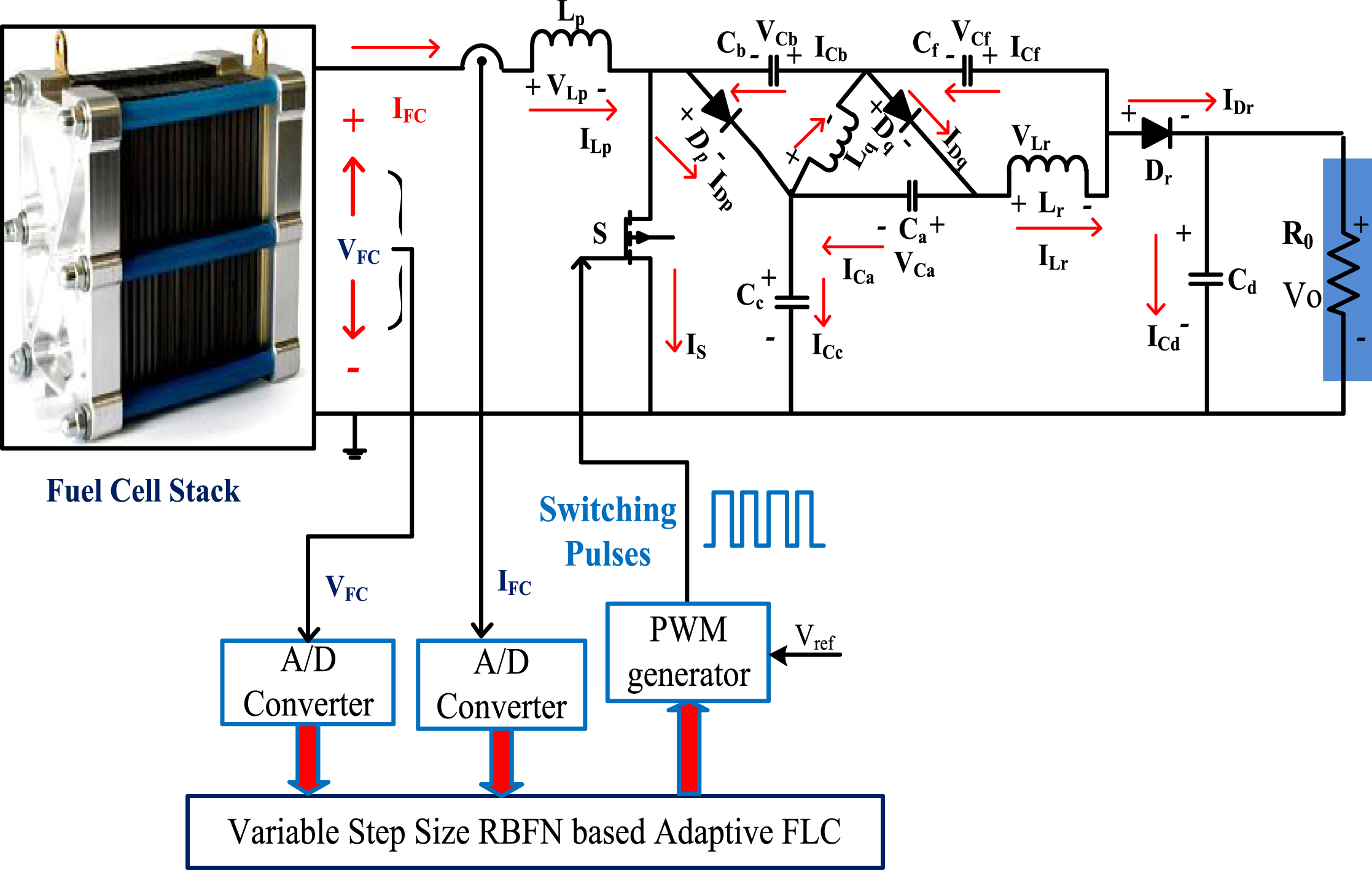
Proposed VSSDE optimized adaptive fuzzy logic MPPT controller.
From the literature review, there are different types of fuel cell technologies are available in the market, and which are used based on their applications [25]. Here, in this work, the PEM fuel cell concept is used for obtaining electrical power. In this PEMFC, the electrolyte, electrodes, gas, and catalyst layers are included. The carbon, an ink of catalyst, and electrodes are painted onto the electrolyte. The carbon paper is pressurized on both sides of the electrodes to protect the entire cell [26]. The architecture of the selected fuel cell is illustrated in Fig. 3 (a), and its related circuit is shown in Fig. 3 (b).

(a). Block diagram of selected fuel cell, [28]. (b). Circuital representation of the PEMFC system.
From Fig. 3 (a), the pivotal part of the fuel cell is a most important three-phase boundary. At the boundary, the catalyst, electrolyte, and reactants are mixed. As a result, the fuel cell chemical reaction happened. Here, the membrane is not conducting electrically, and the working temperature of the cell is greater than 100o C [27]. At this temperature, the cell transforms the chemical by-products into useful electricity by performing an electrochemical reaction. After completion of the chemical reaction, the steam hydrogen comes from the anode side of the cell, and newly generated protons come from the cathode side.
The mathematical derivations of PEM fuel cell are followed as,
The entire voltage obtained from the selected fuel cell is derived as,
From Equation (4), the parameters ‘N’ represents the entire amount of fuel cell quantity, and the obtained fuel stack output voltage is represented as squoVFC’. Similarly, from Equation (5), the terms squoVConce’ and squoEOtdv’ are defined as concentrated, and thermodynamic voltages. Finally, the squoVOhm’ gives the ohmic voltage. From Fig. 3, the open-circuited thermodynamic voltages are determined as,
From Equations (8), and (9), the variables H
a
, plus H
c
are illustrated as comparative moisture vapors at fuel cell anode plus cathode respectively. Similarly, the inlet pressure parameters of the fuel stack are represented as P
a
, plus P
c
. The fuel cell current, area of electrolyte, and pressure of vapor at saturation condition are defined as squoI
cell
’, squoA’, and
The design constraints and their corresponding nonlinear V-I curve is illustrated in Table 1, plus Fig. 4.
Working constraints of proposed fuel cell
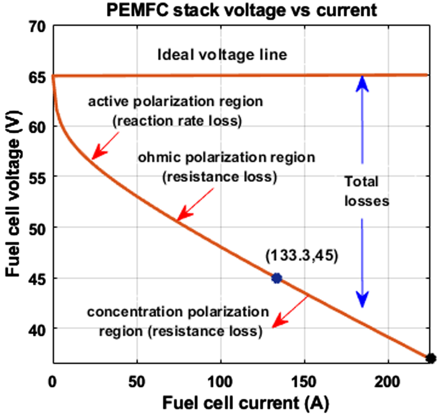
Proposed cell output V-I characteristics.
As of now, there are various categories of power converters are available in the market. However, each converter has its merits and demerits. Here, a single switch dependent DC-DC converter is proposed to enhance the cell supply voltage. In this converter, the switch (s), and supply-side inductor (Lp) are acting like a normal boost DC-DC converter. The variables Ca, Dp, Dq, Cb, Cf, Lq, and Lr are integrated with the conventional boost converter to maintain the system at less power loss conditions. The integrated variables network works as a filter to filter out the fluctuations of cell voltage. Also, it gives a high voltage conversion ratio, moderate voltage stress on switches, and quality load power. The converter works in three stages of conditions which are illustrated in Table 2.
Working states of the power DC-DC converter
Working states of the power DC-DC converter
Here, the Metal Oxide Field Effect Transistor (MOSFET) is working as a switch (S). The working state of the switch under this condition is given in Fig. 5 (a). From Fig. 5 (a), the voltage of the diodes Dp, Dq, and Dr are indicated as VDp, VDq, and VDr. Here, the switch is going to working condition then the related diodes are starting going to OFF condition. The available current of the switch is represented as IS. The three Lp, Lq, and Lr inductors are starts charging up to the period of DTS, and the rising currents of the inductors are illustrated as ILp, ILq, and ILr. The capacitors Cb, and Cf are starting to store the energy, and its related voltages are determined as VCb, and VCf. Similarly, the capacitors Ca, Cc, and Cd are work in an energy discharging state, and their related voltage are VCa, VCc, and VCd.
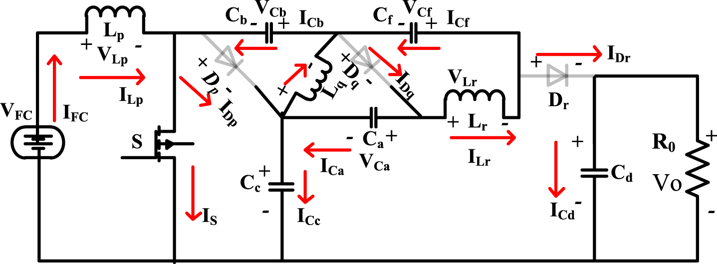
(a) Working of power converter under the first state.
Here, Kirchhof’s Current rule is utilized for the evaluation of inductor voltages as well as capacitors discharging, and charging currents. The variables indication of charging, plus discharging currents of capacitors are ICa - cg, ICa - dcg, ICb - cg, ICb - dcg, ICc - cg, ICc - dcg, ICd - cg, ICd - dcg, ICf - cg, and ICf - dcg. In this working stage, the supply power across the switch is more than the power converter works in Continues Conduction State (CCS), plus Discontinuous Conduction States (DCS) of operations. Here, there are triple assumptions are considered which are illustrated as the first one is selected power semiconductor switches are in ideal condition. The second followed assumption is that the equivalent resistance values of all the elements are zero. The final one is the selected energy storage elements’ values are very high. So that the ripple-free power flows from the fuel stack to the load.
Here Vgs is very less. So, the diodes Dp, Dq, and Dr are starting to work, and its related switch squoS’ is in the blocking stage. The converter works in CCS, and DCS as given in Fig. 5 (b). From Fig. 5 (b), the energy storage elements Cc, Ca, and Cd are starting discharging the electrical power supply. The elements Cf, and Cb are delivering electrical energy. Similar to the previous, here, the KCL and KVL laws are used for deriving the capacitors’ energy storage, and discharging. The mathematical equitation of converter in this working stage is derived as,

(b) Second working stage of the proposed DC-DC converter.
Here, the supply power to the switch is very less. So, the converter works only one stage of operation which is DCS. In this DCS, the converter of all semiconductor devices is in an ideal state as shown in Fig. 5(c). From Fig. 5(c), it has been identified that the three inductor currents flowing through the converter fluctuate. Also, the voltage that appears across each inductive element is zero.

(c) Third working stage of the converter under DCS.
In this stage, the converter working state-I, plus working state-II are selected for the analysis of the DC-DC converter under CCS of operation. Here, the major objective is finding voltage gain which is derived by utilizing Fig. 5 (a), Equation (18), and Equation (20).
Based on Fig. 5 (a), it has been identified that the power semiconductor device voltage is nearly equal to VCc. Here, the Equation (17) to Equation (20) are utilized for the evaluation of the diodes voltage stress which is obtained as,
The voltage gain of the converter is determined in terms of stress across the devices by utilizing the Equation (25)–Equation (27). Same way, the inductor current stress is evaluated by equating the input fuel power to resistive load power.
Here, the charge second concept is utilized for finding the charging, plus discharging currents. Similarly, the currents passing through the power semiconductors devices are obtained by considering the capacitive currents.
The operational waveforms of the power converter under CCS, plus DCS are shown in Fig. 6. Based on the Equation (31)–(39), the current stress of switches is obtained in terms of gain, and the RMS current of each capacitor is derived as,
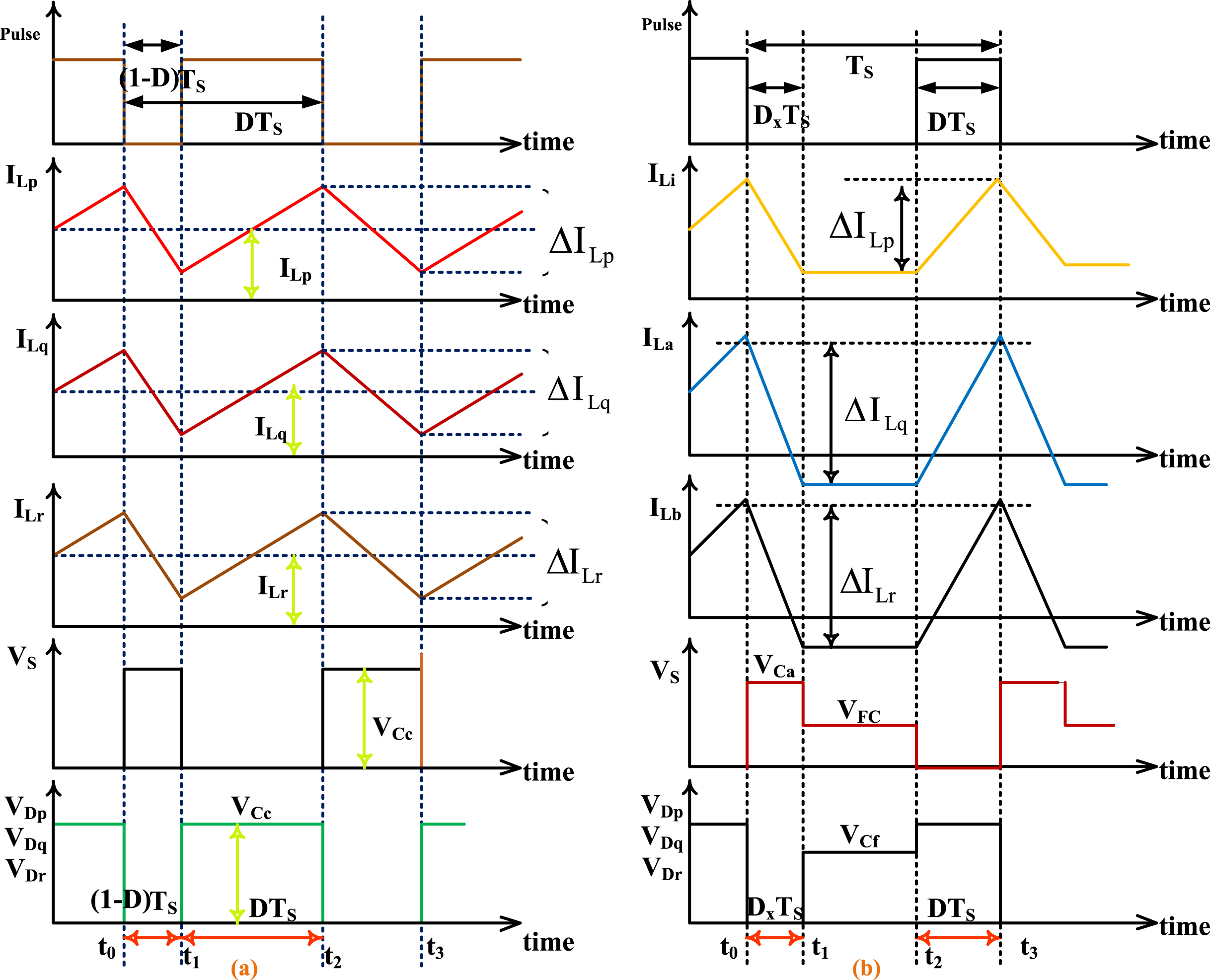
Power DC-DC converter working under, (a). CCS, (b). DCS of operations.
In this discontinuous conduction state of converter operation, the converter overall three switching states are utilized for the evaluation of voltage gain. The converter output voltage at this conduction state is derived as,
From Equation (17), plus (21), the voltage-second concept is utilized for the evaluation of voltage conversion ratio under DCS of converter operation. From Equation (30), the term dx is needed for the evaluation of power converter gain. The Eq’s. (36)–(39) gives the switch current which is equal to the summation of one-third of diode current as well as inductor currents. The peak-peak inductor currents are determined as,
The converter voltage gain constraints are utilized for the evaluation of the boundary condition of the proposed converter. From Equation (26), and (55), the constant of the inductor is obtained as,
From Equation (56), if τ> τbdry then the utilized converter topology starts work in CCS.
In this section, the comparison of the utilized power converter with other transformerless power converters is given in terms of the total number of switches required to implement the power converter, cost of implementation, working output efficiency, and the stress of voltages on switches, and voltage converted ratio. The detailed analysis of power converters is illustrated in Table 3.
A detailed comprehensive investigation of transformerless power converters
Any fuel cell stack gives V-I characteristics in a nonlinear fashion. Also, the working performance of the fuel cell is purely dependent on the membrane of water, fuel composition, partial pressure from the hydrogen, working temperature, and gas constraint. Also, it depends on the partial pressure of the oxygen. Here, the functioning temperature of the fuel cell is utilized for analysis of the working behavior of the proposed system. At fluctuation temperature conditions, the maximum peak power pint of the cell is fluctuate. So, the generation of peak power from the fuel device is quite complex [39]. To overcome this problem, the researchers utilized the MPPT controller for producing the constant load power. In this work, a VSRBFN-based AFLC is proposed to maintain the constant fuel cell voltage with less steady-state distortions. The introduced MPPT method is compared with the other conventional, and artificial intelligence-based techniques such as Adaptive VS-P&O, IVS-INR, and VS-MPFNN.
(a). Adaptive based VS-Perturb & Observe MPPT controller
As of from the current MPPT applications, the P&O is frequently utilized most useful power point finding controller for the transformation of fuel cell deliver power to resistive load [40]. In this method, the fuel voltage and its related working point under various temperature conditions are needed for finding the required MPP position. In general, the conventional P&O method utilized the small step for limiting the oscillations of MPP. But, it gives a poor dynamic response. Otherwise, the selected step value is high for achieving a good dynamic response. In this case, the steady-state behavior of the cell is reduced [41].
To eliminate this issue, in the article [35], the authors used the adaptive enhanced P&O controller. In this controller, an auto-scaling concept is used for adjusting the step value of the controller. The corresponding duty is adjusted automatically based on its MPP location at the various membrane of water contents. The updation of power converter duty has been done by utilizing the Equation (57), and (58). Equation (57) is applied when the functioning point of the cell is another side of the actual MPP location. Else, Equation (58) applied for tracking the actual MPP. The terms D (a-1), plus D (a) indicates previous duty value and an instant duty cycle.
From the previous article publications, it has been observed that the MPPT is the most important research area in fuel cell-fed electric vehicle systems. The major disadvantage of P&O is oscillating power loss at the second perturbation which is limited by applying the INR controller [42]. In article [43], the authors introduced the incremental resistance concept for improving the MPP response as well as steady-state accuracy. Also, this method is more suitable for the practical wider operating range of fuel cells. Here, the P-I curve of the fuel stack is used for high-power industrial load systems. The differentiation fuel stack output power-related current is zero at peak power point place. The delivered error signal from the INR block is derived as,
From Equation (59)–(61), the step value is adjusted continuously until reaching the actual MPP location. At the starting point of the P-I curve, the searching step value is selected more for reducing the accuracy error. Final peak power point position of the P-I curve, the optimum required step value is used for enhancing the dynamic and steady-state response. The duty value of the controller is varied based on the peak load power demand that is given in Equation (62).
From the past literature review, the artificial controllers are formed from the biological neurons. Every neuron in the human brain is represented as a node. The nodes are interconnected with each other in the form of signal transmitters [44]. The multiple numbers of nodes form a multilayer neural network. In article [45], the neural network-dependent power point tracing controller is used for fast finding of MPP location. The neural network works in the following steps creation of approximation model, data set configuration, select the architecture, train the overall model, enhancing the generalized performance, testing of performance results, and deploy the model.
The multilayer perceptron network consists of three major layers such as fuel cell output current, plus voltage receiver layer, hidden layer, and duty signal delivered layer. The input side layer consists of double nodes which take the signals from the input source. The selected middle layer vertices are nine, and those collect the signal from the supply layer. The third layer selected neurons are one as shown in Fig. 7.

An enhanced multiple layer perceptron neural network.
The neural network output error signal is derived as,
The disadvantages of incremental conductance, P&O are compensated by selecting the hill climb controller. In the hill climb controller, the power variation concerning the reference voltage is considered. The differentiation of power variables gives a positive indication then the finding of MPP goes in a forward way. Otherwise, the variation of power goes in the opposite direction [46]. The hill climb controller demerits are more complex in implementation when equated with the basic MPPT controllers, and give less accuracy at the continuous variation of fuel cell membrane water.
To limit the disadvantages of basic HC, in the article [47], the authors focus on the hybrid neural network-based HC method for improving the tracking speed of the functioning point of system. The working architecture of the proposed method is given in Fig. 8. Here, at initial, the fuel cell input parameters are considered by applying the ANN method. After that, the ANN is working on MPP tracing to make the system at peak load condition. Later on, the HC methodology is used to limit the steady-state oscillations of MPP at different membrane water and temperature conditions [48].

Hybrid neural network dependent HC controller.
From the literature, the neural networks are having the disadvantages of hardware dependency, unexplained functioning of the network, assurance of proper network structures, and difficulty in finding the problem solution. The multilayer feedforward networks are having the disadvantages of high training time, more complexity, less accuracy in MPP evaluation, excessive number of iterations required to obtain the optimal solution, and high cost. So, in this work, the RBFN-based AFLC is proposed. The RBF consists of three layers with less complexity. Here, the radial basis function is working by making the nonlinear function into a linear function. So, complex problem solving become an easy task.
Similar to the multilayer network, the RBF network contains three input vertices, and the hidden layer includes fifteen neurons which are selected by applying the empirical process. The final layer consists of one vertex and it gives a required error voltage signal for achieving the high converter output power. The training of hidden layers in the RBF network has been done by utilizing the unsupervised and supervised concepts. At the initial state, the unsupervised methodology is utilized for giving the random values to the input nodes, and weight updating has been done by applying the supervised methodology. The architecture of VS-RBFN is explained in Fig. 9. From Fig. 9, the three layers’ net values, and weight adjustment has been done by using the below equitation.
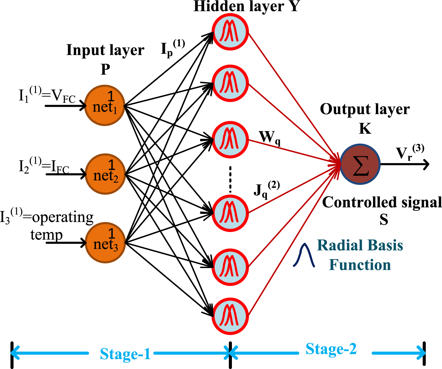
An improved VS based RBF network MPPT controller.
From Equation (76), the voltage error signal is given to the adaptive fuzzy logic controller for obtaining the switching pulses to the power converter. The architecture of fuzzy is shown in Fig. 10 (a), and its related membership variables are given in Fig. 10 (b). The obtained voltage error, and variation of error signals of the fuel stack is given to the fuzzification block for transferring the real values into crisp variables. The selected crisp parameters are fed to the inference block for finding the if-then condition. Finally, the crisp variables are transferred to the real parameters by utilizing the defuzzification concept. The fuzzy rules are explained in Table 4.
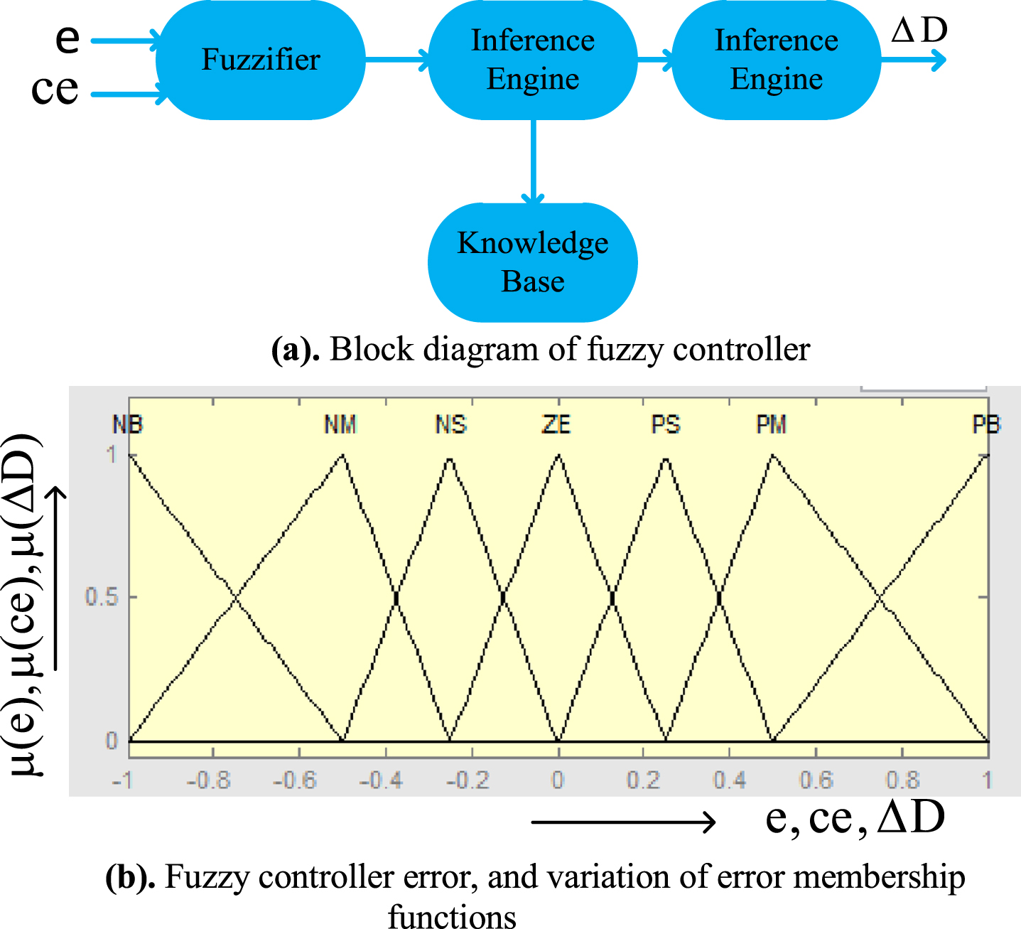
(a) Block diagram of fuzzy controller. (b) Fuzzy controller error, and variation of error membership functions.
Rules formation of adaptive fuzzy logic controller
As from the above DC-DC converter design, the selected input inductor (LP) value is high which is selected as 1.28 mH. This inductor helps make the continuity of power supply to the peak load demand. Also, it is operated to filter the supply voltage fluctuations. The network (D2, L2, and C3) is placed in the middle of the source and resistive load. So that the converter utilization efficiency is improved, and it gives the high voltage transformation. The selected capacitive parameters for the implementation of the DC-DC converter are Ca = Cb = Cf = 280μF. Similarly, the utilized inductor values are Lq, and Lr is equal to 2.6 mH. The interfaced load resistor value for the converter is 46Ω.
Here, the fuel cell gives continuous changes in power and voltage variables. So, the finding functioning point of the fuel stack is moderate complex. Moreover, the membrane water and operating temperature of the cell varies then the fuel stack gives different V-I curves. At every temperature condition, the MPP of the supply is changed. To overcome this issue, in this work, an improved VS-RBF network is used at starting for finding the voltage error of the fuel cell at different step changes in temperature working conditions. After that, the fuzzy concept is utilized to obtain the required duty value for the proposed wide output operation-based DC-DC converter. The proposed MPPT controller is equated with the other artificial related power point techniques at static, and dynamic changes of temperature values.
(a). Constant temperature condition of fuel stack (325K)
At constant working temperature conditions, the working temperature of the fuel cell is 325K. At this condition, the adaptive P&O, improved VS-based INR power point finding techniques are fed to the fuel cell system, and it helps the cell to deliver the maximum power and voltage which are equal to 4.4391 kW, 40.31 V, 4.2324 kW, plus 41.55 V respectively. The enhanced multilayer perceptron neural network-based proposed converter load voltage settling time is 0.045 sec. The converter load voltage, power, plus current-of neural network with HC-based power point tracking technique are 540.22 V, 4.72812 kW, plus 8.7522A. Similarly, the proposed power point finding controller-based converter input voltage, plus currents are determined as 44 V, and 106A. Here, the settling time of converter load voltage by using AVS-P&O, NN-based HC, and hybrid MPPT techniques are 0.036 sec, 0.13 sec, and 0.14 sec respectively.
From Fig. 11 (a), and 11(b), the improved VS-based INR controller gives more efficiency when equated with the conventional P&O controller, and it is evaluated as 96.52%. Also, these controllers give more disturbed converter load current waveforms. But, its design difficulty is moderate. From Fig. 11(c), and (d), it has been identified that the adaptive P&O, incremental resistance power point finding methods doesn’t depend on the fuel cell modeling data and its configuration. Here, the proposed hybrid radial basis functional controller dependent FLC gives the power conversion efficiency of 97.99% which is quite higher than the conventional MPPT methods. From Fig. (e), (f), and (g), the evaluated fuel-fed converter load power by applying the enhanced neural network dependent MPPT technique is 4.66841 kW, and its working performance is highly dependent on the working temperature, and membrane water of the fuel stack. Finally, the improved INR controller converter power steady-state settling time is 0.048 sec.
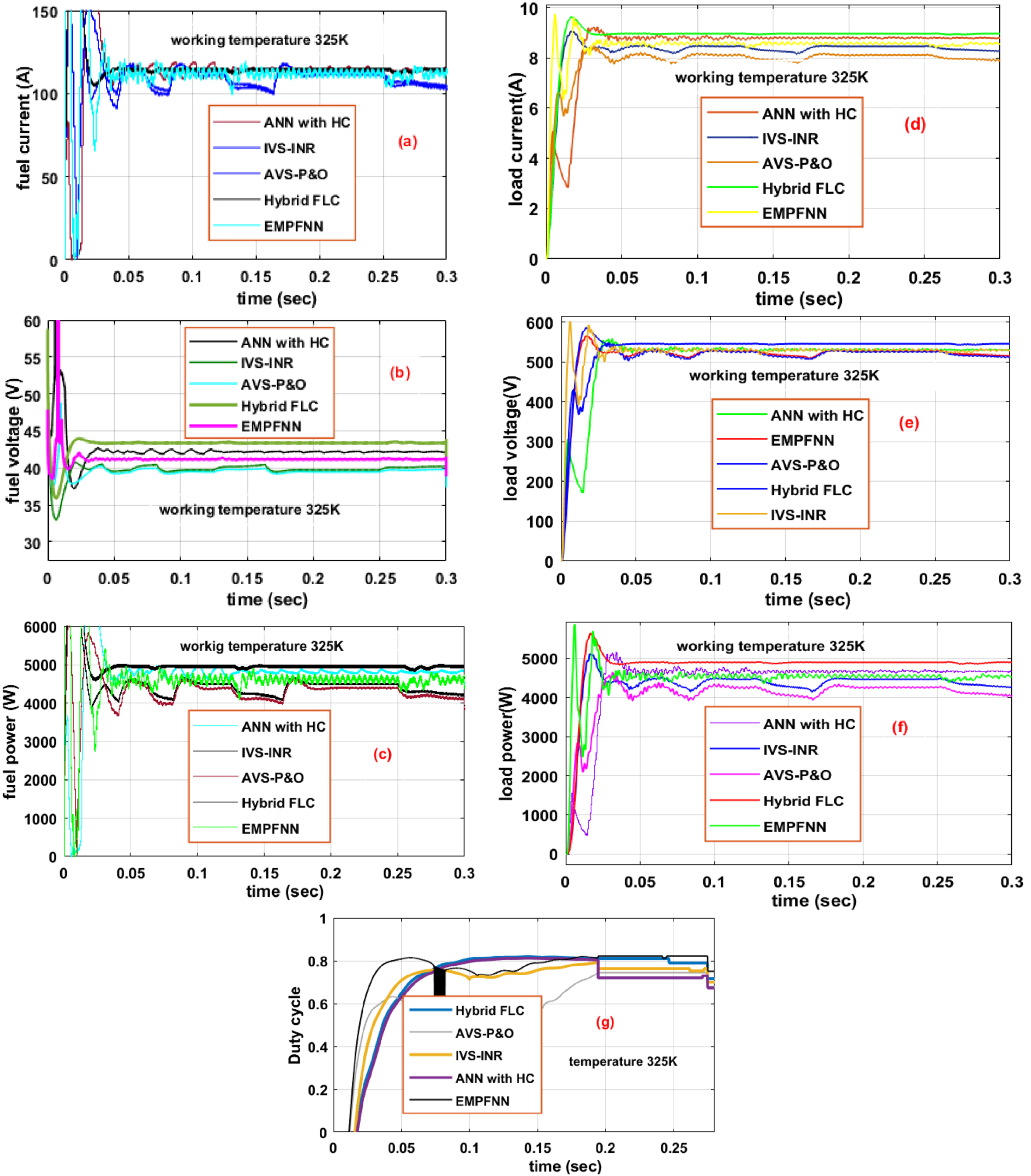
(a) fuel current, (b) fuel voltage, (c) fuel cell power, (d) load current, (e) load volatge, (f) load power, and (g) duty cycle.
In this section, the variables temperature of the fuel cell is selected for the analysis of the proposed fuel-fed DC-DC converter system. From Fig. 12 (a), it has been considered that the starting fuel working temperature is 325K which is maintained constant up to the period of 0.3 sec. Later, the temperature gets to step down from 325Kto 305K. Finally, at 0.6 sec, the fuel operating temperature suddenly raised to 345K. The obtained fuel cell current, power, plus voltages by considering adaptive P&O controller at 305K are 92.02A, 3.671 kW, plus 39.89 V. Also, the converter duty cycle, plus the steady-state stabilizing time of the fuel cell power at 305K are 0.68, and 0.039 sec which is explained in Fig. 12(g), plus 12 (c). Similarly, from Fig. 12 (d), (e), and (f), the improved variable size-INR controller dependent proposed converter load current, efficiency, plus powers are determined as 7.9883A, 96.51%, plus 5.0088 kW respectively. Also, this technique gives high distortions in converter load current.
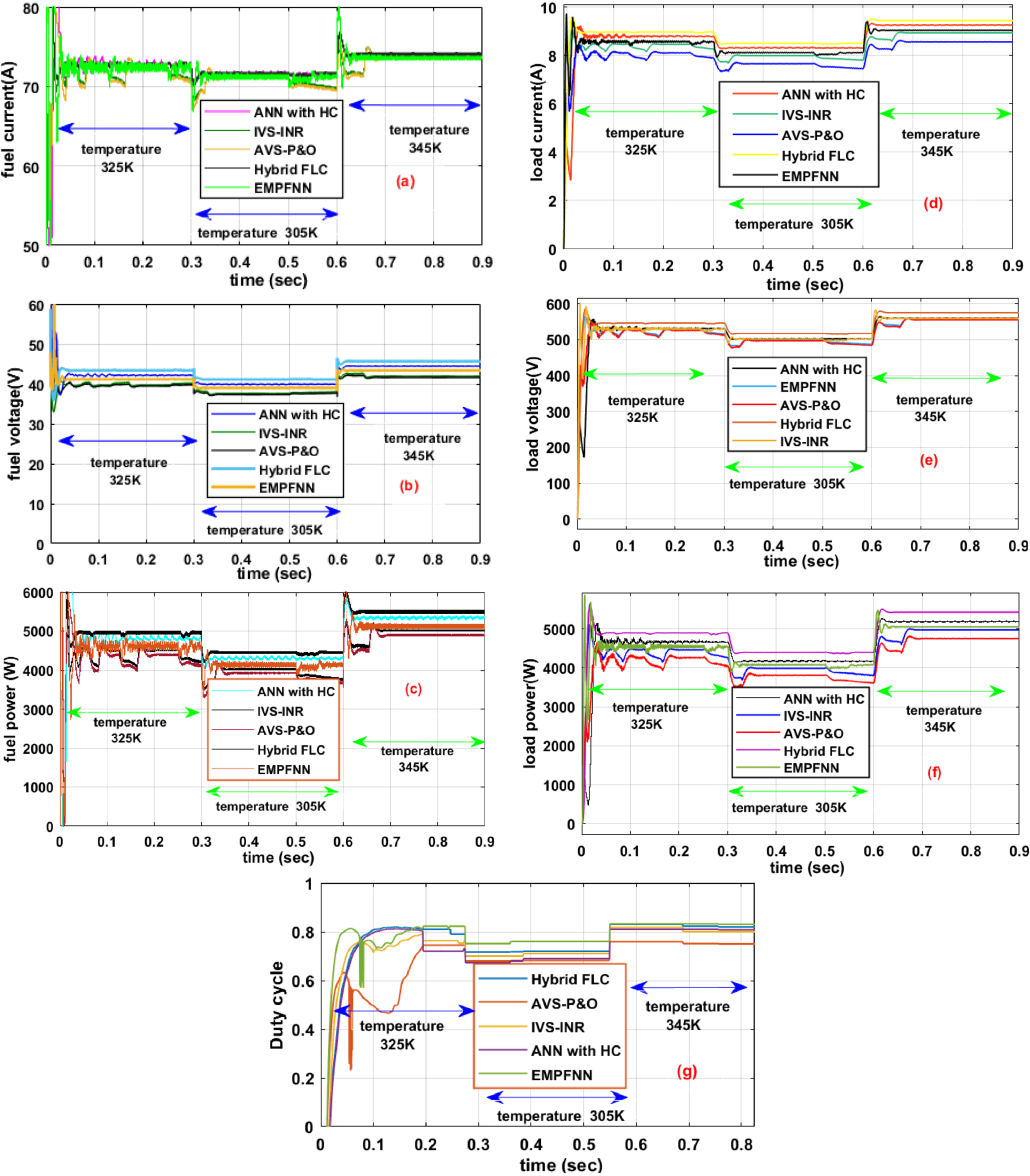
(a) fuel current, (b) fuel voltage, (c) fuel cell power, (d) load current, (e) load volatge, (f) load power, and (g) duty cycle at variable fuel cell temperature condition.
The converter load current by utilizing various power point finding techniques is given in Fig. 12 (d). From Fig. 12 (d), it has been found that the multilayer neural network interfaced fuel-fed power converter step-up the supply voltage from 42 V to 501.21 V. As a result, the converter current falls from 95.92A to 8.3041A. So, the overall proposed system working switching power losses, plus conduction heat losses are optimized extensively. The neural network fed hill climb controller helps the fuel stack extract maximum peak power that can be determined as 42.03 V. Later, it is improved to 504.44 V with the help of the proposed single switch converter. The rising, plus working settling period of converter voltage are 0.14 sec, plus 0.22 sec as shown in Fig. 12 (e). The power conversion efficiency of hybrid FLC at 305K is 97.91% which is quite higher than the adaptive P&O, plus EMPFNN. The detailed analysis parameters of the entire power point finding techniques are illustrated in Table 5.
Analysis of values of various power point finding techniques at continuous fluctuations of working temperature of the fuel stack
From Fig. 12 (f), the proposed fuel system is investigated at 345K. At this input supplied temperature, the conventional adaptive perturb, and observe controller fed fuel cell, and converter currents are evaluated as 109A, plus 8.5547A respectively. Similarly, the obtained converter fuel cell, converter output voltages, and currents by interfacing the improved VS-INR at 345K are 43 V, 112.9A, 568.76 V, plus 8.7748A. Also, the performance efficiencies of EMPFNN, NN with HC, plus hybrid FLC at 345K are 97.55%, 98.22%, and 98.89% respectively. Figure 12, clearly determined that the fuel cell operating temperature improved then the related fuel extracted power, and its corresponding efficiency are improved in an ascending manner. Moreover, from Table 5, the converter power settling, and rising time durations are reduced drastically by utilizing the hybrid fuzzy MPPT technique.
The implemented converter is tested and investigated by selecting the programmed M62020P8058 related direct power supply as shown in Fig. 13. The programmable voltage supply device has the capability of giving controlled DC voltage by interconnecting a rotary switch. The single-phase transformer is used to step down the supply voltage from 230 V to 12 V. So that the overall converter circuit is protected from the excessive voltages of the power supply. The utilized transformer is designed with pure copper winding. The proposed converter is tested with a TLP250 driver controller. The main objective of TLP250 is the optical isolation of transformer and power switches. The parameters of TLP250 are 8-pin IC, threshold current 7–10 mA, and supply voltage 5 V. Also, it consists of GaAIAs light emitted diode which represents the IC output generating the pulses by using the integrated photo detector.

Experimental implementation of single switch converter.
From Fig. 13, the TLP250 consists of 8-pins. The pins-4 and 1 are physically not connected anywhere. The pin-8 is used for the power supply of IC, and pin-5 is grounded for making the power return path. Here, the MOSFET is acting as a power semiconductor switch. The merits of this device are high input impedance, easy manufacturing, high speed of operation when equated with the JFET, high drain resistance due to less channel resistance, ability to scale downsize, and very fast switching capability. The selected testing frequency of this switch is 20 kHz, and its related switching signal is given in Fig. 14. From Fig. 14, it has been identified that the considered duty ratio of the switching signal is 0.1. The experimental selected values of different variables are explained in Table 6.
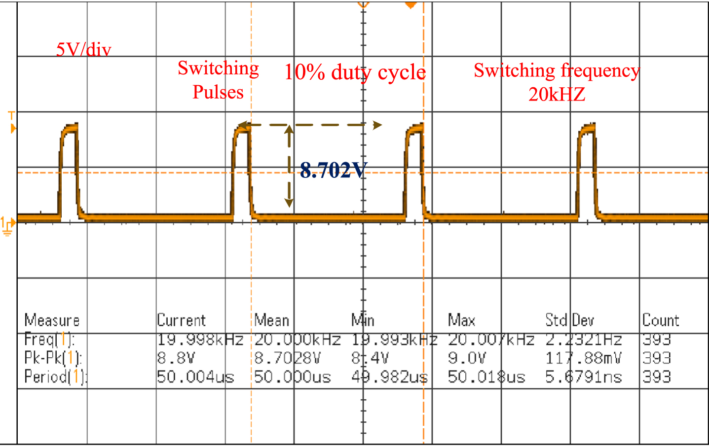
Generation of switching signals for single switch converter.
Experimental specifications of SSUIBC
From Fig. 14, it is stated that the supply voltage of pulse is 8.7 V, and the tested switched time duration under ON condition is DTS, plus the related OFF time duration is (1-D) TS. The switching state of MOSFET voltage is nearly zero, and it comes into the working state then the voltage determined near the drain to the source is 17.22 V. From Fig. 15, the available source voltage generated from the programmable supply is 70 V which is a step-up by applying the optimum duty cycle. Here, the analog discovery is used for giving the pulses to the converter. The output voltage of converter determined by considering the analog discovery is 122.9 V. The features of analog discovery are easier to process analog signals, and gives high density pulses with less bandwidth.
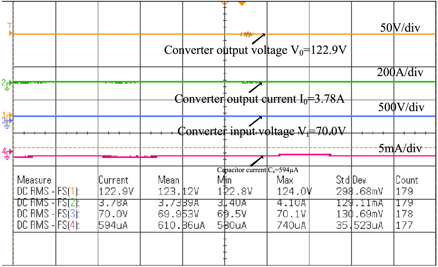
Input, plus output voltage, and current waveforms converter.
The proposed proton exchange membrane fuel stack fed DC-DC converter system is designed and analyzed successfully by utilizing the MATLAB/Simulink software. The merits of fuel cell are lower capex, highest power to volume ratio, fast starting, and high temperature withstand ability. Here, at first, the variable step size radial basis functional network based adaptive fuzzy logic controller is proposed for tracking the operating point of the fuel cell, and controlling the duty cycle of the DC-DC converter. The proposed power point tracking controller is compared with the other conventional MPPT techniques. From the comparison results, the proposed power point tracking controller gives high tracing speed, low oscillations across MPP, easy design, more accurate, and high adaptability. In addition to the MPPT, the new transformerless wide output operation-related DC-DC converter is introduced for reaching the peak load demand. The features of the proposed converter are less voltage stress on power diodes, high efficiency, compact in size, and optimum power losses.