
Abstract
The behaviour of neutrons in a double elliptical guide system is analysed in terms of expected garland, zigzag and point-to-point reflections. From this simple approach, predictions can be made for the beam properties at the focus position and interesting conclusions can be drawn for the necessary guide coating. Analytical results were confirmed by detailed Monte Carlo simulations using the simulation package VITESS.
Introduction
Elliptically shaped devices map a point source onto a point image. Therefore, elliptical neutron guides have been suggested as the best solution to transport as many neutrons as possible from source to focus [7], especially for long distances. First, small elliptic neutron guides have been built and tested at PSI in Switzerland [5]. Then a 100 m long elliptical guide was installed on HRPD at ISIS in Oxford [3].
If the reflection takes place in the first half of the ellipse the divergence is reduced, if it takes place in the second half of the ellipse, the divergence is increased (cf. Fig. 1). Incoming divergence
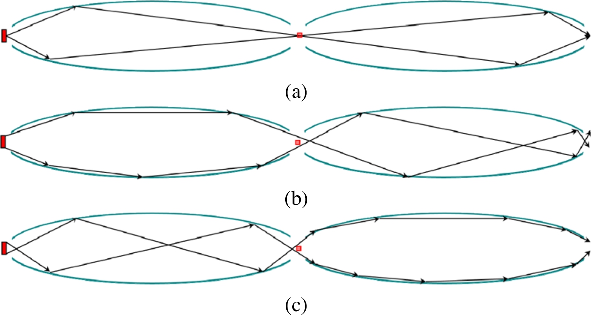
Typical courses of the trajectories starting from the center of the source, i.e. the focal point (a), from a point on the source closer to the wall where the first reflection will take place (b) and a point further away from the wall of the first reflection (c).
Unfortunately, only neutrons from a small area around the centre of the source behave like this (see Fig. 1(a)). If the neutrons start from a position close to the reflecting surface, the reflection angle is significantly reduced and they will be transported by garland reflections (Fig. 1(b)). If they start on the other side of the source, the reflection angle is increased and they undergo zigzag reflection (see Fig. 1(c)), as has been pointed out before [6].
Those being transported by garland reflections will arrive at the first virtual image (the focal point between the two ellipses) closer to the reflecting wall. This means that they are now further away from the reflecting surface in the second ellipse and will undergo zigzag reflections in the second ellipse (see Fig. 1(b)). On the other hand, those being transported by zigzag reflections in the first ellipse, will arrive at the central focal area further away from the reflecting wall in the first ellipse and therefore closer to the reflecting wall in the second ellipse. So they will undergo garland reflections there (Fig. 1(c)). Therefore, symmetry between the trajectories in the first and second ellipse only exists for neutrons which are reflected only once (per dimension) in each ellipse (see Fig. 1).
This simple finding has the following conclusions:
The angle inversion from the first ellipse is only reverted in the second ellipse for neutrons from the center of the source, which are reflected only once per dimension in each ellipse. So reversion of trajectories and phase space takes place only for those neutrons. If zigzag reflections are excluded in each ellipse, e.g. by making one side in each dimension absorbing in the first ellipse and those on the opposite side in the second – SELENE principle [8] – only neutrons with one reflection in each ellipse can arrive at the focus. In this case the angle reversion works and the phase space is recovered after the second ellipse. As a consequence, position and divergence need not be restricted at the source (unless it is the aim to achieve background reduction further upstream). If low divergence is wanted at the focus position, the coating in the first ellipse should allow high divergence, while it can be significantly reduced in the second ellipse. Increasing the distance between the guides should have the effect that neutrons with garland reflection in the first ellipse also undergo garland reflections in the second ellipses (while those with zigzag reflections are lost).
Confirmation of the analytical results by Monte Carlo simulations
We have performed Monte Carlo simulations of the example above using the simulation package VITESS [4,10,11] in order to confirm the basic idea and the four conclusions drawn from these analytical considerations.
As the aim of this study is to investigate the geometrical effect, the system is kept as simple as possible: no gravity is included and no guide waviness is considered. To avoid losses of trajectories, a coating of high reflectivity is usually used (
Ellipses of 25 m half axis along the beam and 50 mm half axis in both directions were chosen giving a total source to focus distance of 100 m. Source and focus have a size
Change from zigzag to garland reflections and vice versa
The example mentioned above was simulated. The simulation was run in a way that those neutrons heading towards the nearer wall were separated from those heading to the opposite side of the guide. Figure 2(a) shows the first trajectories of neutrons directed towards the near wall, Fig. 2(b) those directed in the other direction. The guide is double-elliptic in both dimensions, but the figure shows only the projection to a horizontal plane.
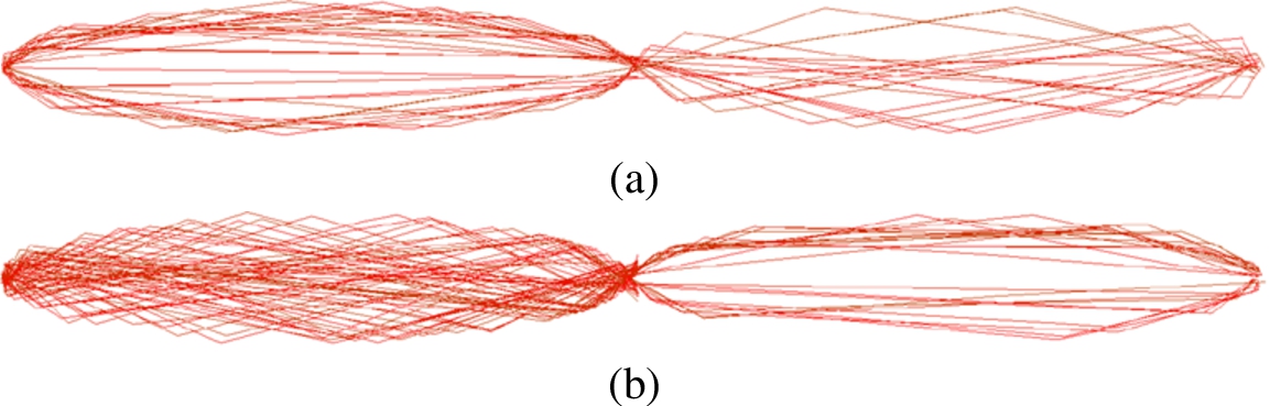
Visualization of neutron trajectories inside a double elliptic guide: (a) neutrons heading for the nearest wall (
These ray-tracing simulations fully confirm the basic assumption that neutrons undergoing zigzag reflection in the first ellipse are transported by garland reflections in the second ellipse and vice versa.
To verify the first conclusion all trajectories were allowed, but the source size varied,
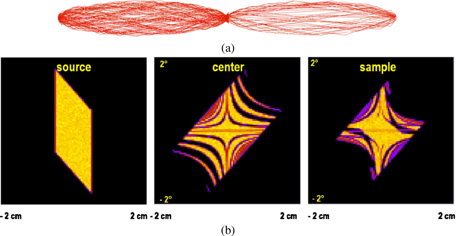
Visualization of trajectories (a) inside a double elliptic guide for neutrons starting from a source of
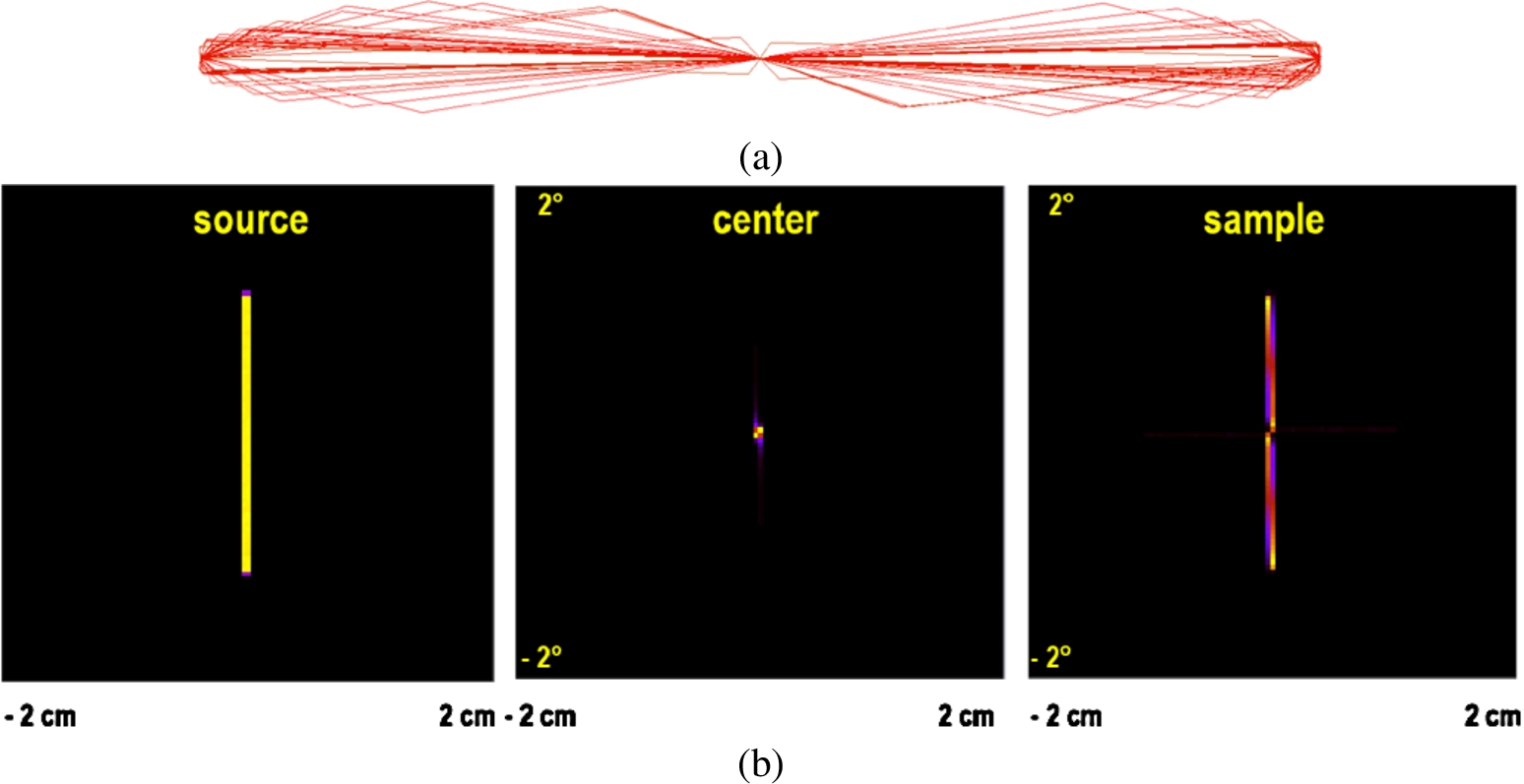
Visualization of trajectories (a) inside a double elliptic guide for neutrons starting from a source of
The results confirm that a reversion of the trajectories does usually not take place (see Fig. 3(a)); and consequently the phase space is not restored, but it is nevertheless closer to the original one (Fig. 3(b)). Reversion of phase space only works in special arrangements, e.g. if the source is very tiny (see Fig. 4). Another possibility is to leave out the ends of the guide, where the multiple reflections occur, and use only the middle sections of the elliptical guide. This was used for the so-called SELENE principle [8].
The simulations were repeated with two absorbing walls in both parts of the guide, top and left in the first part and bottom and right in the second. The resulting phase space at the same three positions: source, central focal point and focus are shown in Fig. 5 together with a number of trajectories.

Visualization of trajectories (a) inside a double elliptic guide that has absorbing walls on one side (left and top in the first ellipse and right and bottom in the second ellipse) and (b) the resulting phase space distribution at the source, between the two ellipses and at the focus position.
The absorbing surfaces on either side of each ellipse lead to one reflection in each ellipse for most of the neutrons (that are not absorbed in the first ellipse). However, the reversion of the trajectory in the second ellipse is imperfect due to the extended source. This avoids again a reversion of (the accessible part of) the phase space (see Fig. 5). So this conclusion was disproved by the simulations.
The conclusion about the influence of the coating was checked using a wavelength of 2 Å. The reflectivity of the coating of the vertical walls of the second ellipse was kept constant at
Increasing the reflectivity has indeed different effects in the two ellipses: in the first ellipse it increases the brilliance with a minor increase in divergence. However, the reflectivity of the second ellipse defines a limit that cannot be exceeded by further improving the coating in the first ellipse (see Fig. 6). In contrast, a higher reflectivity in the second ellipse increases the flux at the focus only by increasing the divergence, not by increasing the brilliance.
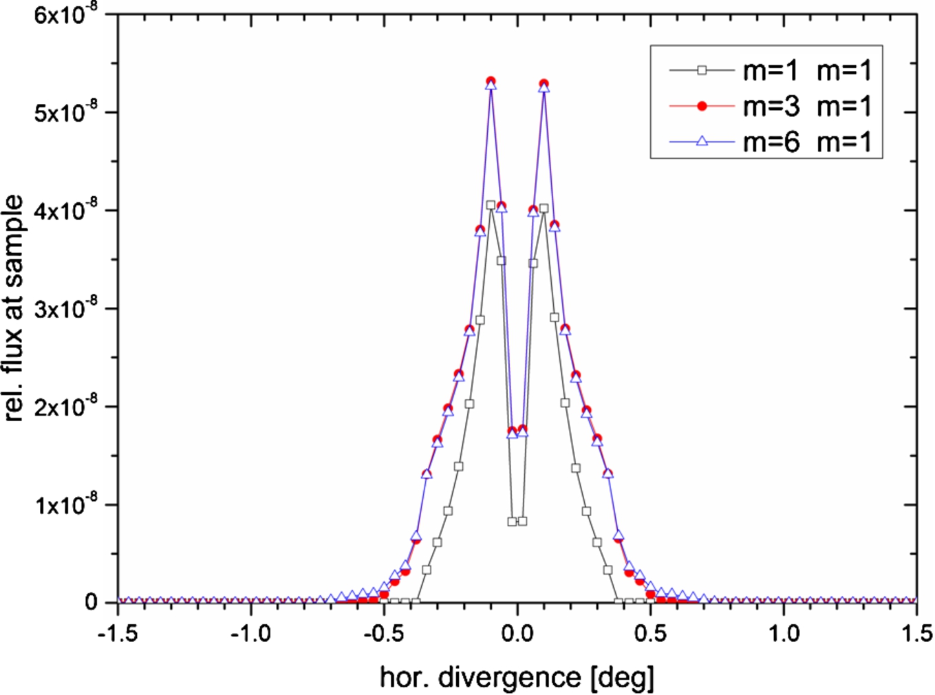
Horizontal divergence distribution at the focus position for different coatings of the first ellipse. The wavelength is 2 Å.
This gives some hint how to choose the coating of a double elliptic guide: first the coating of the second ellipse should be chosen to reach the acceptable divergence, then the coating of the first ellipse should be improved until the limit in brilliance is reached.
The distance between the ellipses was increased up to about 1 m distance of the focal points. Again trajectories were recorded for different distances and the horizontal divergence distribution is monitored.
Indeed, increasing the distance between the two ellipses (by a sufficiently large amount) results in garland reflections in both ellipses (Fig. 7) and reduces the divergence at the focus significantly (Fig. 8). The drawback is a significant loss of brilliance (up to a factor of 2).
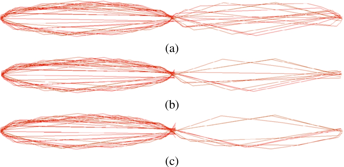
Visualization of neutron trajectories inside a double elliptic guide with different distances between the central focal points: (a) 20 cm, (b) 50 cm and (c) 100 cm.
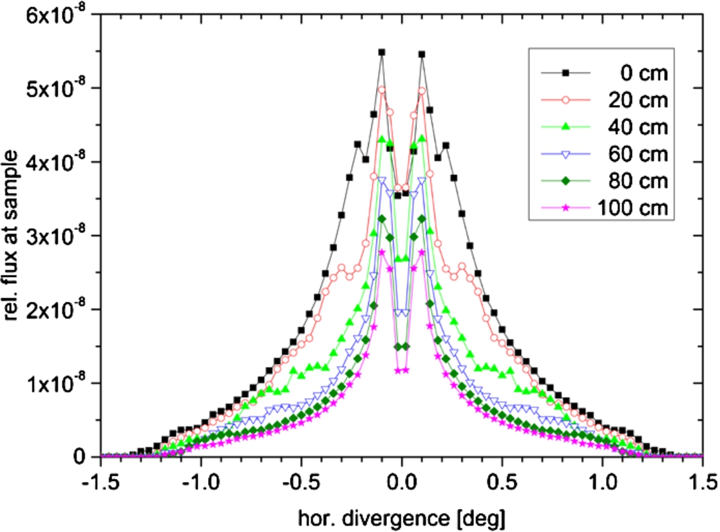
Horizontal divergence distribution at the focus position for different distances between the central focal points of the two ellipses. Wavelength is 2 Å, coating
While these simulations give hints how to design a double elliptic guide in the best way, there remains the question about its performance in comparison with other geometries.
One simple check would be a comparison with a simple guide of constant cross-section using the same wavelength ranges, coatings and sizes.
A possible way to improve a double elliptical guide system is to avoid losses in the central part of the double ellipse by connecting them with a guide of constant cross-section. This opens up the possibility to widen the exit of the first and the entrance of the second ellipse to reduce the number of multiple reflection at the guide ends. In the extreme case, the guide system consists of one half-ellipse, a straight guide of half the total length and another half ellipse. This geometry would keep the basic concept of 2 reflections to the focus for all neutrons reflected in elliptic section. Repeating an earlier study [9], the cross-section of the straight guide is increased and the lengths of the elliptical sections is reduced to get the same cross-section at the exit of the first and the entrance of the part of the guide from the originally used values (
The result is shown in Fig. 9: A double elliptic guide clearly outperforms guides of constant cross-section. Increasing the distance between the ellipses reduces the brilliance transfer in the whole wavelength range, which was observed for one wavelength already before.
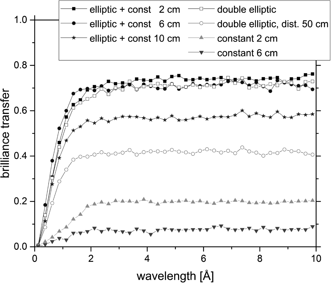
Brilliance transfer as a function of wavelength for guide systems of 100 m source to sample distance, but different geometries and cross-sections. The elliptic guides have cross-sections between 2 and 10 cm, details are given in the text.
Connecting the elliptical guide with a guide of constant cross-section slightly improves the brilliance transfer. A moderate increase of the constant guide has little influence, but opening it up to the full cross-section reduces the performance. This finding is different from results obtained earlier [9] and requires further investigations.
Simple analytical considerations about garland and zigzag reflections allowed predictions about the behavior of neutrons in a double elliptical. Most of them could be confirmed by ray-tracing simulations, which on the other hand showed also the drawbacks and limitations.
The idea of looking at neutron trajectories through the guide system is a promising way of getting insight into the details of the beam transport. So this approach can lead to an improvement of the performance of a guide system and its adaption to the needs of a special instrument.
The double elliptic set-up can be optimized this way. Under normal conditions – extended source and complete guide – it does not transport all neutrons by 2 reflections per dimension to the focus and therefore does not restore the original phase space. So under these conditions, it is not an optical device, but it is still a well-performing system for neutron transport.