



Abstract
This paper provides an overview of the current development of the ISIS robotic cryogenic sample changer. The system combines a collaborative industrial 6-axis robot with novel adaptions to the traditional vanadium sample can and the closed cycle refrigerator (CCR), producing a simple robust solution for automating sample changes at cryogenic temperatures. Results have shown that the proof of principle has been successful. Future work is focussed on further integration of the robot system with the cryogenic equipment and refining system operation.
Keywords
Introduction
The ISIS neutron & muon source is located at the Rutherford Appleton Laboratory in the UK. ISIS operates two targets stations, providing over 1800 international users per year access to 30 beamlines. The facility comprises of a 70 MeV LINAC feeding a dual harmonic proton accelerator, producing 200 μA, 800 MeV protons to two independent targets. Proton extraction is such that TS1 operates at 40 Hz and TS2 at 10 Hz repetition rates, producing 128 kW and 32 kW respective target power.
ISIS has a total of 26 neutron and 4 muon instruments covering diffraction, spectroscopy, reflectometry and SANS techniques. On completion of the TS2 Phase-II construction project an additional four instruments will increase the SANS and reflectometry instrument suite with ZOOM and LARMOR whilst adding neutron chip irradiation with CHIPIR and neutron imaging with IMAT [8].
Supporting this diverse range of techniques is an equally diverse range of sample environment. Sample changers enable the automation of the sample changing task on select instruments. Typically diffraction and SANS measurements see the greatest benefits from sample change automation due to the potential for high experimental throughput.
To date, sample changers are designed and developed with a single application in mind, usually to be operated at a specific beamline. This is driven by variation in beamline construction, samples and associated containers, interfaces with existing sample environment equipment, thermometry, sample positioning and automation requirements. Finding a solution that provides a standard platform for sample changer development with the capability to cope with a range of beamline and experimental variations would significantly reduce the associated capital and resource costs.
Industrial robots have the kinematic capabilities and repeatability to be an ideal candidate [10]. By associating sample placement and positioning tasks with an industrial robot system it is possible to use a single off-the-shelf platform to develop sample placement solutions in conjunction with, often, pre-existing sample environment.
Concept and principle of operation
Cryogenic sample changer design poses a substantial level of engineering complexity and although many issues can be solved in the lab, translating lab success to robust user operation is fraught with risk. The ISIS robotic cryogenic sample changer mitigates many of these risks by isolating the cryogenic environment from the motion system. The enabling principle, isolating motion from low temperatures, is to flow Helium through the CCR, creating a pressure differential, transporting the sample can and replacing the requirement to mount a sample can on a sample stick. This method simplifies robot automation tasks, increases sample storage volume and reduce sample cool down times.
Collaborative industrial robot
Collaborative industrial robots have risen in popularity in recent years and are estimated to have strong growth in the industrial robot market in the future [7]. Low capital investment and ease of use has enabled collaborative robots to widen the scope of robotic applications, from traditional heavy industry into small and medium enterprises. A primary attribute of a collaborative industrial robot is the potential to operate the system without physical guards or machine interlocks; when compliant with the risk reduction methods outlined in BSEN ISO 10218:2011 [1] and ISO/TS 15066:2016 [9]. Supporting attributes of collaborative robots include 3D motion simulation and interactive teach modes to reduce the technical expertise required in providing robotic solutions.
Universal robots – UR5 robot specification
The UR5 from Universal Robots [11] was selected for the sample changer application. Universal Robots manufactures the UR3, UR5 & UR10 robotic arms which are designed to operate with 3, 5 & 10 kg payloads respectively. A subset of the UR5 technical specifications are given in Table 1.
UR5 robot technical specification
UR5 robot technical specification
Robot motion solutions have been developed using a transportable robot test stand, pictured in Fig. 1, comprising of a platform to mount the robot, a free surface for positioning associated equipment, an area housing the control PLC and a Perspex tube complete with sample carrier representing the CCR. The experimental setup is completed with gas sources for gas transport and gate valve operation, a solenoid valve to control the flow of gas through the Perspex tube assembly, a Lakeshore 350 to read sample can thermometry and a PC to program the robot controller and develop the master-slave control interface.
Robot control development
To date development of the robot control functions includes the positioning of the sample can and control of gas through the sample volume [5], development of an advanced pick and place routine using gripper force detection to verify sample status before changing sample [4] and a sample audit routine to check the status of a single sample position in the sample rack or sequentially check each sample position [6].

Robot test stand.

3D printed sample can baffle assembly.
Sample can baffles
As previously noted the gas transport technique provides a means to disassociate a sample can with a centre stick; movement through the CCR is controlled by the flow of exchange gas underneath the sample position. A baffle assembly attached to the can, as shown in Fig. 2, impedes the gas flow creating a pressure, forcing the can out of the CCR. The parachute shape of the top baffle is designed to ensure that the sample can captures exchange gas, keeping the can in a gas atmosphere throughout the sample movement and ensuring that the can moves reliably through the convoluted bore of the isolating gate valve. The baffle assembly was developed using 3D printing methods and was printed from ULTEM 9085 resin.

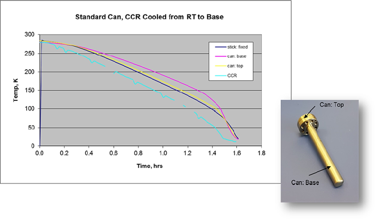
Vanadium sample can temperature differentials, body inside to outside.
Sample can temperature differentials, body to flange.
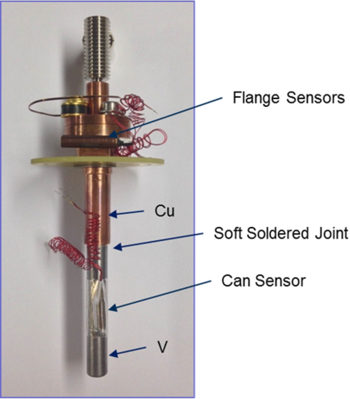
V-Cu sample can thermometry setup.
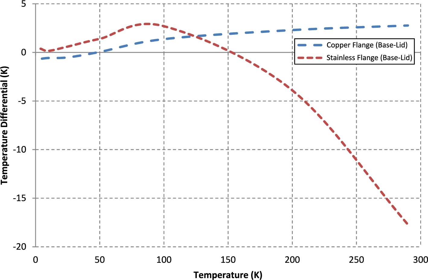
V-SS, V-Cu sample can temperature differentials.
Improving the quality of sample can thermometry is a persistent goal within sample environment. A number of experiments have been completed at ISIS in the past to explore temperature differentials across a standard Vanadium sample can. The results in Fig. 3 & Fig. 4 show that, for this particular sample, there is a minimal differential between the sample temperature and the can body throughout the CCR operating temperature range. However, the differential between the can body and the Stainless Steel flange is significant in the range 250K to 70K. It is clear, therefore, that an improvement in sample can temperature measurement can be made by increasing the thermal conductivity between can body and flange. Figure 5 shows a new sample can design using Copper in place of Stainless Steel at the sample can flange. Figure 6 provides a comparison of temperature differential between Vanadium Stainless Steel (V-SS) and Vanadium Copper (V-Cu) constructed cans. It can be seen that the V-Cu design has significantly reduced the temperature differential by circa factor 2 producing an almost a flat response across the operating range 300K to 4K.
Sample can thermometry contacts
Without the sample stick wiring infrastructure a new technique was developed to provide automatic connection of sample can thermometry during a sample change. The sample can is constructed with a fixed PCB which, when the can is seated in the sample position, depresses a set of sprung Cu-Be contacts mounted within the CCR sample carrier, providing a connection between the fixed thermometry wiring in the CCR and the sample can temperature sensor. Figure 7 provides images of the sample can PCB.

V-Cu sample can with PCB.

Contact resistance distribution.
In automated thermometry connection schemes the reliability and electrical characteristics of the contact is fundamental to the accuracy of the measurement. Initial tests were completed at room temperature to examine the reliability and quality of the contact method. The tests were conducted by substituting the sample can temperature sensor for a
Sample can sensor
In general Rh-Fe sensors are used for low temperature measurements on ISIS sample cans. For the sample changer application Si-diode sensors are being evaluated. Si-diode sensors have two clear advantages over resistance thermometers in this application. Firstly the measurement will be less sensitive to the contact resistance change highlighted in Fig. 8 because at cold temperatures the diode forward voltage is many orders of magnitude larger than the contact resistance voltage.
With regard to neutron beamline operation, it is noted that care must be taken to establish the operational limit of the Si-diode sensor with exposure to radiation [2].
Cryogenic system
Figure 9 provides a model view of the modified CCR. The CCR is modified with a capillary to flow exchange gas underneath the sample can and a sample carrier, complete with contacts and wiring to provide an automated connection for sample can thermometry. The gate valve is positioned at the top of the CCR sample tube to provide a method of automating the sealing of the sample space.

Modified CCR, 3D model.
Figure 10 provides an image of the CCR Helium capillary inlet mounted above the sample carrier. It can be seen that the capillary is for the most part made of Copper, thermally anchored to the 1st stage of the CCR with a short Stainless Steel portion between the 1st and 2nd stage to provide a weak thermal link.
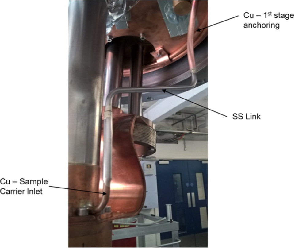
CCR exchange gas capillary & inlet.

Modified CCR. Room temperature to base, cool down response.
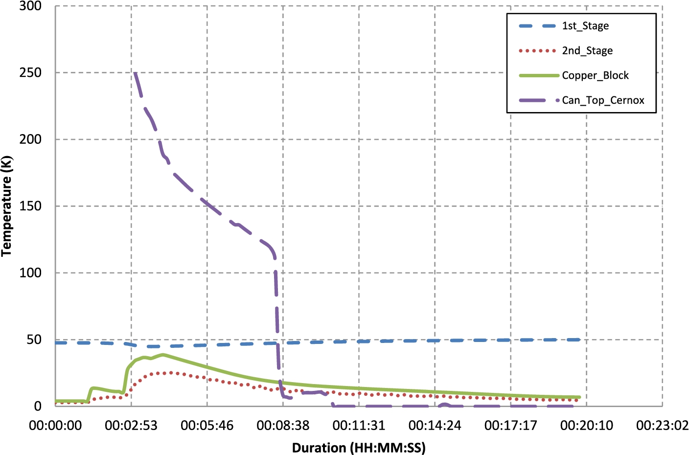
V-Cu sample can. Room temperature to base cool down response, 10 mbar exchange gas.
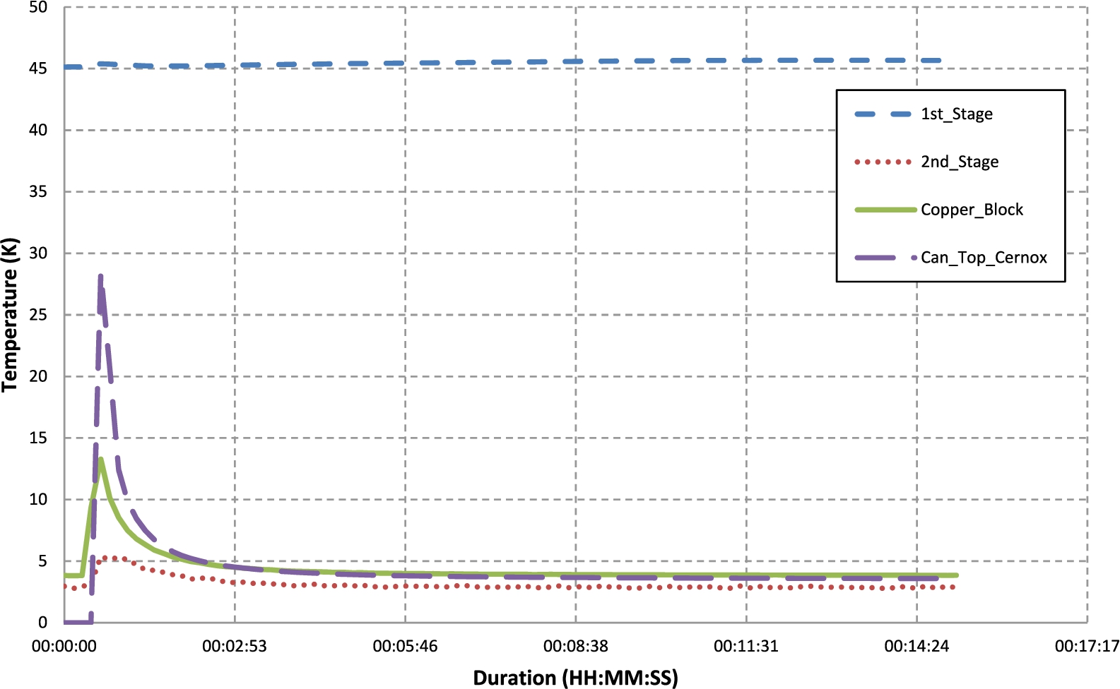
V-Cu sample can. CCR at base. Addition of 20 mbar exchange gas.
Figure 11 shows that the modified CCR cools from room temperature to base in circa 3.5 hours, highlighting that the introduction of the capillary, sample carrier and associated wiring has not been detrimental to CCR operation.
Cold gas transport
On establishing sufficient flow through the capillary a number of tests were performed to prove the gas transport method and observe thermometry contact reliability at low temperatures. Movement of the sample can through the CCR was successful operating with a gas pressure of 3.7 bar at the gas source regulator [3].
Sample can cooling
Figure 12 highlights measurements taken from the sample can thermometer via the CCR sample carrier contacts in an exchange gas environment of 10 mbar Helium. It can be seen that, the improved sample can design in position without sample stick, provides a very fast sample can cooling response from room temperature to base in circa. 7 minutes.
Low temperature contact reliability
Due to time constraints testing at low temperatures has been minimal but it is clear that contact reliability is reduced in comparison to room temperature results. Figure 12 shows that, shortly after a contact is made there is an issue resulting in a null reading. This is rectified by blowing additional exchange gas re-seating the sample can and providing a robust contact, seen in Fig. 13.
Conclusions & future work
As a proof of principle this project has been a great success. Collaborative industrial robots have been identified as an excellent candidate for sample environment sample changer development providing a minimal capital investment, easy to use, flexible and portable platform with the kinematic repeatability to perform sample pick and place routines. The method of using exchange gas to transport a sample can through a CCR at base temperatures has been successful with a rapid sample cool down time in the order of 7 minutes. Future development will focus on understanding the long term reliability of the automated thermometry contact, integrating the robot with the CCR and associated automation of exchange gas processes. At this stage of the project this development looks strong for a simple, reliable and portable cryogenic sample changer.
Footnotes
Acknowledgements
The following ISIS Sample Environment Group, Electronics User Support Group and ISIS Design Division team members are acknowledged for their support and continued hard work throughout the project: Steve Wakefield, Jeff Keeping, Rob Major, Jon Bones, Jason Chandler and Colin Offer.
This project has been funded by the ISIS Facility budget.