




Abstract
RIKEN Accelerator-driven compact neutron source, RANS, has been operational since 2013. There are two major goals of RANS research and development. One is to establish a new compact low energy neutron non-destructive evaluation system on-site of floor-standing type for industrial use. Another goal is to invent a novel transportable compact neutron system for the preventive maintenance of large scale construction such as a bridge. For the realization of the preventive maintenance usage with neutron methods for non-destructive test of large scale structures on-site, “Standardization”, such as inclusion in manuals and inspection procedures, is essential. Technology research association for the infrastructure preventive maintenance standardization is established. RANS and RANS-II are in operation, and RANS-III, and RANS-μ, neutron salt-meter, are under development.
Introduction
RIKEN Accelerator-driven compact neutron systems have been developed to realize neutron systems on-site use [5,9,10]. The primary goal of our research and development is to expand the scope of neutron beam applications and to realize systems that can be used where and when it is needed. There are two major goals of RANS (
The reason why RANS is developed based on the linear accelerator is that according to Japanese radiation regulation, the use of linear accelerator whose energy is less than 4 MeV is allowed for bridge inspection. We have developed RANS, RANS-II [6], RANS-III [2] currently under development are based on proton linear accelerator with different proton energy of 7 MeV for RANS, and 2.5 MeV for RANS-II and III, using different kinds of target as beryllium for RANS and lithium for RANS-II and III, respectively.
RANS has been playing a role in proving how much compact neutron system is useful, and valuable by showing specific measurement results with quantitative low energy neutron imaging including CT, engineering diffraction method [5], for the characterization of microstructure in such metals as iron and steel, small angle neutron scattering [7], neutron induced prompt gamma-ray activation analysis for the non-destructive diagnostics method of salt concentration of the concrete structures [16], fast neutron transmission imaging [13] and neutron scattered imaging for large scale concrete structures [3]. Fast neutron scattered imaging method is now up-graded so that it enables to detect such small degradation less than 1 cm diameter air hole, or water existence in the composite floor slab [1]
Next section, RANS project will be explained in detail.
RANS project
In this chapter, some results which shows certain potential of compact neutron systems by RANS will be explained, first. The present status of RANS project is explained with the comparison of RANS, RANS-II, RANS-III, and RANS-μ.
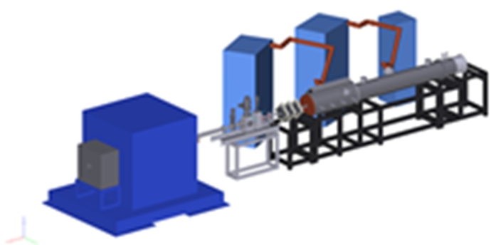
RIKEN Accelerator-driven compact Neutron Source, RANS. Proton linear accelerator of 7 MeV (right), target station (center) with Be target and neutron beamline exit (left).

Neutron spectrums at the exit of target station of RANS, about 1.5 m down from the target for different kinds of polyethylene moderators, without 0 cm, and with 2, 4, 6 cm thick moderators.

Pole figures of IF reference steel obtained from the measured neutron diffraction patterns through the Rietveld texture analysis [17]: (a) RANS, (b) TAKUMI (J-PARC), (c) HIPPO (LANSCE).
Figure 1 shows that the neutron beam can be delivered from the target station, and according to each experiments, user can install various measurement apparatus as imaging table and detector, or diffractometer, or PGAA sample Ge detector stage down from the target station along the neutron beam. The neutron energy spectrum at the 1.5 m down from the target is shown as in Fig. 2. The user can choose such energy variation by changing the moderators among different thickness of the polyethylene.
Here, we will introduce one measurement case that has been developed and demonstrated with RANS. It is texture evaluation with engineering diffraction; such measurement will be evaluated with RANS-II and eventually is expected to be used where necessary to meet the needs of industrial use, such in the manufacturing field.
The neutron engineering diffractometer of RANS has been developed from 2014 [5] based on the strong request from the steel companies and on the collaboration with material researchers in Japan. The aim is to realize such engineering diffraction system that enables volume fraction of retained austenite can be easily estimated through whole iron and steel samples. Texture determination before and after the plastic processing can also be done on-site. So, we have developed the engineering diffractometer, and up-graded the measurement systems, including shielding system. The diffractometer is always situated down from the target station of RANS shown as in Fig. 1
At RANS, one diffraction pattern measurement of the iron sample with about 1 ∼ 1.5 cm3 volume takes about one to three minutes with coupled moderator of 4 cm or 2 cm thick polyethylene, and about fifteen minutes with decoupled moderator. The retained austenite volume fraction evaluation of RANS diffractometer agrees with that of J-PARC Takumi-beamline measurement within 1% accuracy with full angle measurements [4], while the energy resolution is not so good as such diffractometer at the large facilities as Takumi.
For the texture evaluation estimation, with the interstitial-free steel (IF steel) sample the comparison among RANS, Takumi, and HIPPO of LANSCE has been done. The polar figures and orientation distributions are shown in Fig. 3 [17]. The detailed condition and methods how to obtain these pole figures are explained in [17].
The results, Fig. 3, show that RANS can give the same results as that of the instruments of large facilities such as J-PARC, and LANSCE. One of the reason why RANS, compact neutron system, enables to reach the same results is that RANS can cover all poles as necessary, although the energy resolution is not so good. Users can choose long or short measurement time according to their request, for example, measurement accuracy, and/or number of the samples that they want to measure during one day, and so on, at RANS. They will be hopefully able to perform more or less the same neutron quantitative analysis not only with engineering diffractometer, but neutron imaging CT (computed tomography) with providing the reconstruction of 3-dimensional imaging, or small angle neutron scattering experiment with RANS-II, as well. As a result, we expect that the RANS-II model will be introduced to such companies in the future, including users who want to make sure that the products they are developing are kept in-house for daily use.
Actually, RANS-II has two objectives. The first objective is to demonstrate, as a prototype for RANS-III, the realization of a transportable neutron system that can be used outdoors. The neutron generation condition, the combination of the proton energy and the target material is the same for RANS-II and III, so that we have proved the system, RANS-II, capable of stable operation of 2.5 MeV protons and lithium targets, first. RANS-II has also been used to verify the technology of neutron scattering imaging as nondestructive test of infrastructure. The next goal for RANS-II is to become a model case for non-destructive testing equipment used in house by companies and other organizations.
As one of the realization of the first goal of RANS-II, the backscatter visualization technique developed with RANS [3] is now up-graded. The non-destructive visualization for smaller and thinner degradation as 3 mm air gap is successfully developed for such realistic on-site model as in the composite slab of concrete and steel with RANS-II [1].
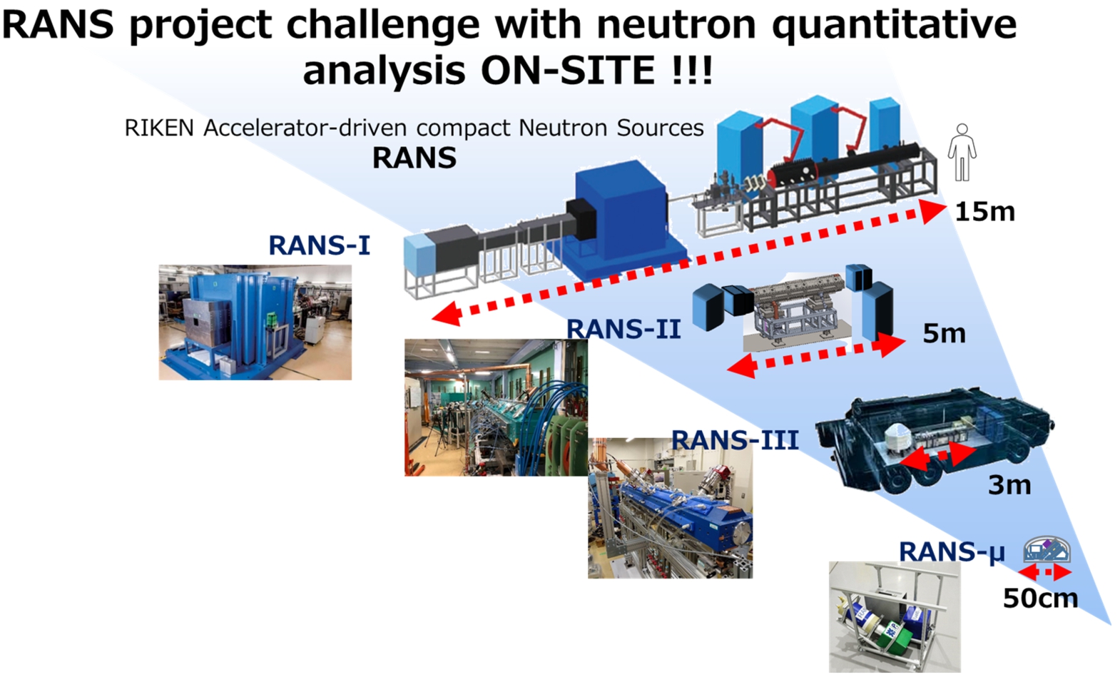
RANS project challenge to meet the on-site needs for non-destructive test with neutron quantitative analysis.
The present status of RANS project, the size challenge with the comparison of each compact sources are shown in Fig. 4.
As shown in Fig. 4, RANS-III is designed to be truck-mountable, e.g., 3 to 5 m long, with about 5ton of the weight Non-destructive detection of the internal degradation under the pavement of highway, and that of the floor slab of bridges is the key subjects of RANS-III.
The smallest model in Fig. 4 is “RANS-μ”. This is the new and urgent research and development to realize as light and small as possible, in response to a strong request by the Public Works Research Institute of the Ministry of Land, Infrastructure and Transport for non-destructive neutron detection of severe salt damage around the bridge girders which are behind the floor slabs. RANS-μ is “neutron salt-meter”, to meet the demand for measuring salt density distribution inside and around the girders located behind the bridge floor slab. It consists of the 252Cf neutron source, Germanium gamma-ray detector and the neutron and the gamma-ray shielding. The salt density distribution in the concrete is measured by using Neutron-capture Prompt Gamma-ray Analysis (NPGA) technology. The neutron salt-meter, which measures the girder behind the slab, has size and weight limitations. These limits are determined by the specification of the bridge inspection vehicle. Details are given in [15]
The RANS, RANS-II and RANS-III are pulsed neutron sources and use a pulsed proton linear accelerator for its generation. RANS is based on a radio frequency linear accelerator, and the proton beam energy of 7 MeV is reached by two-stage acceleration of the radio-frequency quadrupole (RFQ) and the drift-tube linac (DTL) with a duo plasma ion source. In order to reduce the size and the weight of the system, the proton beam energy is decided as such value as 2.5 MeV, so that the accelerator in RANS-II and III is RFQ only with the electron cyclotron resonance (ECR) ion source. The lower proton energy also has such advantage as the reduction of the weight of shielding surrounding the target, actually the weight of RANS-II target station is reduced as small as 1/7 times lighter than RANS. The compactness for the trans-portable system, the challenging development of the proton accelerator of RANS-III is based on higher frequency of 500 MHz with rigid structure [2] based on three-fold system of RFQ based on the patent [12].
The list and the comparison between the RANS, RANS-II, and RANS-III are shown in Table 1.
RANS, RANS-II, RANS-III
For the realization of the preventive maintenance usage with neutron methods for non-destructive test of large scale structures on-site, “Standardization”, such as inclusion in manuals and inspection procedures, is essential.
The
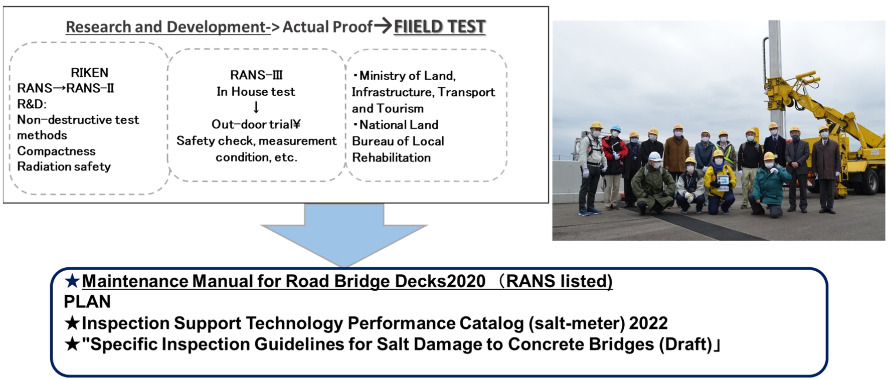
Towards the standardization from Research and development non-destructive test for infrastructure with RANS based on T-RANS, and T-RANS member picture at test bridge in Fukushima with bridge inspection vehicle.
The flow and the plan of this standardization of RANS technology with T-RANS member picture is shown as in Fig. 5.
The non-destructive method to evaluate the water movement in the concrete samples with RANS is listed already in the “Maintenance Manual for Road Bridge Decks 2020”. The RANS-μ is now under development and is aiming to be listed in the “Inspection Support Technology Performance Catalog” until the end of 2022, based on the development of RIKEN and the technical support by T-RANS.
The RANS projects goals and overview are introduced as well as an example of a quantitative measurement technique with engineering diffractometer for texture evaluation based on RANS that can be used on-site.
For the realization of the preventive maintenance usage with neutron methods for non-destructive test of large scale structures on-site, “Standardization”, such as inclusion in manuals and inspection procedures, is essential, so that Technical association, T-RANS was established and starts its activities.
RANS, RANS-II are now in operation, and RANS-III, and RANS-μare under development.
Footnotes
Acknowledgements
A part of this research was carried out as “Research and development of salt-meter with neutron source for on-site nondestructive inspection of bridge structure”, the commissioned research of “Tohoku Regional Development Bureau” under technology research and development system of “The Committee on Advanced Road Technology” established by MLIT, Japan. It was also supported by JSPS KAKENHI, Grant Numbers 25289265 and 25420078. The authors would like to thank the Iron and Steel Institute of Japan (ISIJ) Research Group for their beneficial assistance.