
Abstract
In order to improve the positioning accuracy of indoor robots, a new positioning method has been designed based on passive RFID. In this paper, RFID beacon is arranged as cellular model, the card reader efficiency is improved. RSSI positioning method correction model is put forward with engineering practice, the optimal value problem is solved with multiple beacons in positioning process. Differential Evolution algorithm is introduced, physical verification is designed within the scope of (4×4) m2, the experiment results show that the absolute error is less than 10.16 cm. Compared with the standard genetic algorithm, the optimal value can be obtained in the smaller iteration step, 37% less computation time has saved.
Keywords
Introduction
Indoor mobile robots have received much attention because their wide application prospects, one of the core contents is the accurate location information in their research, it is the basic characteristics of moving objects parameters, it is also the basis for robots to be observed and controlled (Dean & Ghemawat, 2010). However, when the mobile robot is in the indoor environment, because of the building environment, there are various types of material barriers to block, there are these result in multipath effect, uneven distribution of field strength, or even unpredictable and other issues, the signal interference and serious fluctuations are made (Junhua et al., 2012), therefore, for the indoor environment, mobile robot location information acquisition research has been the hot and difficult of the basic research and development of robotics.
Radio-frequency-identification (RFID) technology is essential for a nontouching recognition system, it transmits and processes the information on events and environments, a wireless frequency and small chips are used (Hahnel et al., 2004; Flores et al., 2005). The RFID system can recognize tags at high speed and send the tag data within various distances. Therefore, the application of the RFID technology has recently been increased and it has been applied for robot technology (Kubitz et al., 1997; Kulyukin et al., 2004). With the development of the personal robot and advanced ubiquitous network robots, it is essential for the robots to recognize their own location and environment, and high security is maintained in a common space with people. If RFID technology is properly applied to the robot, the robot can provided the services for the users at anytime and at any place.
GPS positioning method is currently the wide used technology, the positioning accuracy is difficult to meet the requirements for the indoor environment, and even search is difficult (Jing et al., 2012). Visual technology is used for location information acquisition, but also it is the current mainstream research content, there are light effects, reference markers has excessive impact and other issues on the positioning accuracy (Xun et al., 2003); The Zigbee, WLAN and other wireless technology positioning are used, multi-path effect is strong, and the active device laying conditions have high cost (Lee et al., 2008). Infrared, ultrasonic and other sensors are used, it can provide more accurate location information, but there are still multipath and non-line-of-sight effect (Yongfeng et al., 2016). Although relying on a path to perform position estimation, it can reduce the dependence on external sensors, the generation and elimination of cumulative errors with the increase of the path becomes a difficult problem to solve. Radio Frequency Identification (RFID) is a kind of non-contact sensor technology, RFID has the advantages that traditional sensor technologies do not have, and RFID can exist passively and is not affected by the external environment such as light and smoke. At the same time, it is unique in its own storage of data. As a position recognition object, compared with other positioning methods, it has the characteristics of strong anti-interference, direct and rapid data reading, and RFID is suitable for application in indoor environments. RSSI (Received Signal Strength Indication) is a received signal strength indication, it is an optional part of the radio transmission layer, it is used to determine the link quality, and whether to increase the broadcast transmission strength. The normal range of RSSI can be: [–93, –113], and if it exceeds this range, it can be regarded as an RSSI exception. The RSSI (Received Signal Strength Indicator) is used to receive the signal strength indicator, the signal node and the distance are calculated between the positioning objects (Zhi & Hui, 2013; Zhen et al., 2007), good support is provided based on RFID robot location acquisition mode. Therefore, combining with two kinds of position acquisition methods, it is suitable for indoor environment, it can improve the positioning accuracy of mobile robot.
Because of the laying of RFID tags, there is a gap between the tags. Once one or more reader detections are difficult to obtain the relative position information between the direct readers and RFID cards, the accurate position needs to be obtained by mathematical estimation. The Maximum Likelihood Estimation Model (MLE) is a common used position estimation method. Because the mathematical concept is clear and the derivation is simple and easy to understand, it is used in early indoor positioning methods (Lihong et al., 2014). At the same time, the introduction of genetic algorithm (GA) translates the position information estimation process into a minimum problem, the efficiency and accuracy of position estimation are improved under multi-RFID tag signal conditions, and GA has also been used in indoor mobile robot position estimation in recent years. Therefore, the quality of the optimal value is also the main factor that affects the real-time and accuracy of positioning accuracy.
In view of the above problems, this article starts with the RFID-based positioning method, the principle of RSSI positioning process is analyzed, RFID and RSSI technology are integrated to propose a robot positioning method, it can be conveniently applied to indoor. In order to further improve the positioning accuracy, this paper compares the MLE, GA several methods for position estimation, such as the differential evolution algorithm (DE), the applicability of DE is verified to the localization environment and methods in the paper. Finally, experiments are conducted to ensure the completeness of the experimental data and plan a variety of forms of movement trajectory for the mobile platform, a detailed analysis is done for the experimental results.
Mobile robot localization algorithm
RFID tag placement model
The passive RFID positioning method requires the RFID tags, they are arranged according to the following listed rules. Each RFID internal storage needs a unique identifier, and the position of each tag corresponds to a certain coordinate value of the indoor space. The reader is carried by the robot, the beacon information is read in the signal range, and then the current position of the robot is calculated. RFID tag layout models are often square and honeycomb type, as are shown in Fig. 1.

Beacon arrangement model.
The label arrangement model is constructed according to the square, the most intuitive problem is that the tag spacing model is not uniform. The complexity of position estimation calculation is brought about. When the reachable range of a card reader signal is fixed, the number of detected tags changes too much within the detection signal range, it can easily cause disorder in accuracy. When the reader signal range is small, the indoor robot moves between two columns or two rows of RFID tags, it may exist a blind spot of coordinates between two or two rows of RFID tags, there is a larger position error in missed detection. For the shortcomings of the square arrangement, the cellular beacon arrangement model has the same distance between each beacon, and within the same signal range area, the cellular network can save the number of RFID tags. In the square, the equilateral triangle and honeycomb arrangement model, honeycomb arrangement can produce the smallest static error (Shaohui et al., 2015). Therefore, in the absence of RSSI robot position estimation, the cellular RFID tag placement model can provide more accurate location information, while it reduces the missed detection of RFID. In practice, when moving in the longitudinal direction, the possibility of inadvertent reading of the RFID signal can be reduced due to the position accidental factors. Common passive RFID beacon coordinate estimation method mainly has the mean coordinate position estimation, it is shown in Equation (1).
In the formula (1), m is the number of RFID tags which were included in the reader’s signal atmosphere, (xi, yi) represents the coordinate value which was corresponding to each beacon, and (xest, yest) represents the coordinate estimate value. In this way, the RFID tag coordinate average value will be read in the reader signal range, they are corresponding to the total average value of the x-axis and y-axis value, it is a simple and fast method, but there is the larger error. When the beacon spacing is in 1/2 signal range, the maximum static error is r. r is the radius of a single cell circumscribed circle in Fig. 2.

A Method of Positioning Estimation Based on Coordinate Value.
The HL estimation method was proposed by Han et al. (2007). HL estimation method arranges the RFID tags on the floor in a new triangular pattern, it can reduce the estimation error of the conventional square pattern. In addition, the motion-continuity property of the differential-driving mobile robot has been utilized to improve the localization accuracy of the mobile robot. The HL theorem is a theorem to prove the congruence of two right triangles. It is proved that the two triangles are congruent by verifying that the right, and right sides of two right triangles are equal. The decision theorem is: “If the hypotenuse of two right-angled triangles is equal to one of the right-angled sides, the two right-angled triangles are equal (abbreviated as HL)”. The formula is shown in Equation (2). Under the same conditions, the method can reduce the maximum static error to r/2.
Under the same conditions, the HL estimation method can reduce the maximum static error to r/2. But the positioning accuracy obviously did not meet the control requirements of mobile robot.
RSSI (Received Signal Strength Indication) is a received signal strength indication, it is also an optional part of the radio transmission layer, it is used to determine the link quality, and whether to increase the broadcast transmission strength. According to the principle of signal space propagation, the logarithmic normal distribution model is used, the position relation between the robot end reader and the RFID tag can be expressed in the formula (3) (Jiajia et al., 2009; Vanheel et al., 2011).
In the formula (3), di represents the distance between the i-th tag and the reader, p(d0) is the RSSI intensity value in the unit distance, n is the signal propagation constant, and where the hardware device determines p(d0), n can be obtained by means of regression analysis; at the same time, the card reader is racked in the mobile platform, the measured di distance and the ground can not ignore the angle, which needs to be amended, the modified formula is in Equation (4).
In the formula (4), l is the height of the card reader, di _ est is the distance between the card reader and the measured beacon, that is, the error of the positioning information is eliminated due to the detection height of the card reader. Under the condition that the coordinates of the beacon distance position are obtained, the relationship between the current coordinate and the measured beacon coordinate satisfies the system of Equation (5).
Maximal likelihood estimation iterations are used to obtain (xest, yest) values (Bo et al., 2013), but there is still the improvement space in accuracy (Bo et al., 2014).
The Equation (5) are transformed into the Equation (6) (Yongfeng et al., 2016), the coordinate point estimation to the optimal value problem, when the optimal value of Equation (6) tends to the minimum value, the obtained (xest, yest) will tend to be more realistic.
Differential evolution (DE) is proposed by American scholar Storn and Price in 1995. It is an algorithm to simulate the law of natural evolution, and in its research report, it is proved that the convergence rate and stability of this algorithm was more than the adaptive simulation evolutionary algorithm (ASA), evolutionary strategy (ES) and stochastic differential equation (SDE), especially when the differential evolution algorithm is used for real parameter optimization. With this feature, in the access card reader signal range and within a number of beacon coordinate information conditions, the multi-point location information is calculated. DE evolution can be simply described as: for each individual in the previous generation population, three different individuals are randomly selected, and one of them is used for the base individual, the other two do the disturbance in the direction, the corresponding new individuals are obtained, The new individual and the old individual cross to obtain the competition individual, the better individual is retained through the evaluation function evaluation, the evolution is achieved (Storn & Price, 1995). Differential evolution is based on the criterion of minimum evolutionary generation and convergence conditions. The differential evolution algorithm is terminated when the evolutionary generation condition is satisfied or the convergence condition is satisfied (Li Xun & Qu, 2012).
In evolutionary computation, differential evolution (DE) is a method that optimizes a problem by iteratively trying to improve a candidate solution with regard to a given measure of quality. Such methods are commonly known as metaheuristics as they make few or no assumptions about the problem being optimized and can search very large spaces of candidate solutions. However, metaheuristics such as DE do not guarantee an optimal solution is ever found.
DE is used for multidimensional real-valued functions but does not use the gradient of the problem being optimized, which means DE does not require for the optimization problem to be differentiable as is required by classic optimization methods such as gradient descent and quasi-newton methods. DE can therefore also be used on optimization problems that are not even continuous, are noisy, change over time, etc. (Rocca et al., 2011).
DE optimizes a problem by maintaining a population of candidate solutions and creating new candidate solutions by combining existing ones according to its simple formulae, and then keeping whichever candidate solution has the best score or fitness on the optimization problem at hand. In this way the optimization problem is treated as a black box that merely provides a measure of quality given a candidate solution and the gradient is therefore not needed. The optimization DE algorithm of Equation (6) can be found in (wikipedia.org).
In order to verify the applicability of DE for the localization problem, the maximum likelihood estimation iterative algorithm, the standard genetic algorithm and the differential evolution algorithm are used respectively, and the optimal value calculation is carried out for the optimal value calculation problem. The experimental parameters are shown in Table 1.
GA, DE optimization algorithm basic parameters
Assuming the number of detectable RFID tags m < 8, the coordinates are randomly obtained, the iterative results are shown in Fig. 3.

MLE, GA, DE optimization iterative curve.
It can be seen from the iterative evolution curve that the differential evolution algorithm is superior to the MLE and GA algorithm in terms of the maximum value and the number of iterations, and it can get the optimal value within 157 steps, it is saving 37% of the standard GA calculating time.
Experimental environment and path description
Experimental environment construction
As the controllable wheeled car has a simple hardware structure, easy to control, track adjustable measurable advantages, so in this article, it is used as a mobile platform. The total area of the experimental environment is 16 m2, X and Y are 400 cm, and the lower left corner of the map is the origin. In the process, r = 25 cm (r is the radius of the circumcircle of the single cell hexagon), the RFID card pitch is 25
Experimental path planning for mobile platforms
In order to ensure the completeness of the experimental data, two experimental paths are designed for the trajectory of the moving platform, as shown in Fig. 4 (a) and (b).
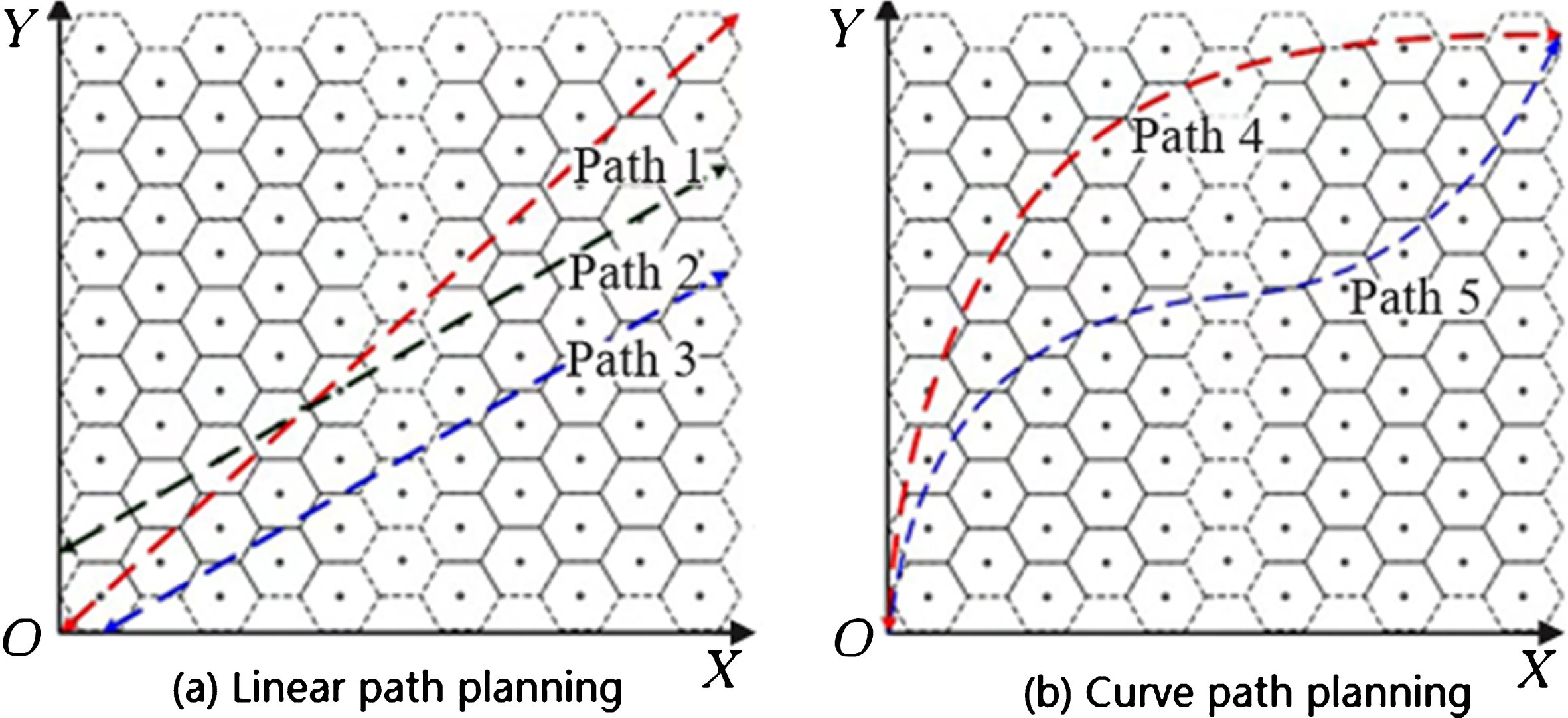
Mobile platform experimental movement trajectory diagram.
Figure 4 (a) mainly contains three straight path, the experimental field diagonal movement is done in path1 path mobile platform; path2 is in accordance with the RFID tag, it is arranged in a direction of the line to move; path3 is in accordance with the RFID signal distribution interval midpoint connection. In the Fig. 4 (b), path4 does a radius of 400 cm and 1/4 arc trajectory movement; path5 is in accordance with the program in the mobile platform, a good track is designed to move. Through the movement of the mobile platform, the straight line, the curve and the movement process position information can be recorded accurately, and it is compared with the positioning information, the accuracy and practicability is ensured in the method.
Radio Frequency Identification (RFID) is the wireless communication via radio waves that uses three main components in this system: a computer, an interrogator and a tag (Fig. 5). The interrogator (also known as a reader) continuously broadcasts a RF (radio frequency) signal through the antenna. Any tag (also known as a responder) within the RF field is an activated tag that rebroadcasts a signal along with the unique data stored on the tag. The reader then captures the signal from the tag and transfers the data to the computer where it is processed through middleware and stored in a database. Figure 2 also displays a wireless RFID system, in which the interrogator has WiFi capabilities to communicate to a wireless router connected to the computer. Significantly, the tag data that the reader transfers to the computer can be utilized in many ways by querying the database for the tag’s unique ID number. RFID systems are classified as either active (powered by battery). passive (powered by RF wave), or semi-active/passive (both).

Components of a wireless RFID system.
Passive RFID tags do not transmit power, but rather reflect the power back to the antenna, called incident power. In order for a passive tag to operate, the reader must supply the operating energy to the tag through the transmission of an RF wave. The output power is the energy the reader sends out. The tag then reflects the signal back (consuming some in the process). The Received Signal Strength Indicator (RSSI) is the measurement of how much power is received by the reader from the tag, relative to the original signal strength from the reader. The signal strength propagates and reduces when the distance between the antenna and tag is increased. The further away a tag is, the lower the RSSI. The maximum RSS is the power output from the reader, and the minimum is the signal strength needed to operate the tag.
Therefore, knowing the output power from the antenna and the performance characteristics of the antennas and tags, an approximation of the tag location can be made. The Friis transmission equation is used to calculate the power received by an antenna (Ahson & Ilyas, 2008), when transmitted from another antenna. Free-space path loss is proportional to the square of the distance between the transmitter and receiver. Additionally, path loss is also proportional to the square of the frequency of the radio signal. Tracing the power to and from the reader can provide insights into both tag detection and the RSSI.
Due to the limitations of the mobile MCU’s calculation speed, the calculation is performed on the PC side, the data acquisition frequency of the platform reader is set to 10 Hz, the movement speed of the mobile platform is 25 cm/s. The mobile platform is set to pause every second, and the current card reader reading is output. The uploaded PC value is calculated according to HL, MLE, GA, and the DE method. The final positioning value is the average value which is obtained by 10 estimation methods. To ensure real-time requirements, the total number of iteration steps is limited to 200 steps. Experimental results and data analysis are as follows:
(1) Linear trajectory motion results and analysis
Path1 path is for the experimental plane diagonal movement, the positioning results are shown in Fig. 6.

HL, MLE, GA, DE positioning comparison chart in planning path 1.
It can be seen from the positioning points in the method. At the initial origin, because the number of RFID tags that the reader can cover is the least, in the HL method, it is calculated by the single-point label coordinate value, errors are larger, and the other three methods are carried out according to RSSI, The distance between the mobile platform and the RFID tag is larger, and the positioning point is larger than the path of Path1. The MLE method is limited by the total number of iterations, the optimal value of the positioning value can be approximated, it is less, it deviates Path1 from planning the path.
From the record of Table 2 positioning results, the relationship between the mobile platform and the label position have a major impact to the positioning results. Table 5 5–7 line are MLE positioning results, the mobile platform is currently located in the middle position of the two labels, the reader signal coverage label number is less, and there is a missing standard, a larger positioning absolute error is produced, but the resulting positioning error can maintain a high accuracy in DE here.
MLE, GA, DE positioning results in Path 1
As can be seen from Table 3, in the planning path 1, because the total number of the iteration steps is limited, not each positioning estimate can be approximated to the optimal value in the MLE method (Table 1), a variety of error values are larger, the maximum error of the path is close to r, it is in (95.1, 73.3); the obtained positioning results are compared with the standard GA and DE methods, the average accuracy difference is small, but according to the contrast of the maximum error value in Table 2, the error of DE method has a smaller advantage than the GA method, the DE algorithm can make the optimal value in the smaller iteration step, and a contribution is made to the improvement of the positioning accuracy.
MLE, GA, DE all kinds of errors in Path 1
Planning path 2 is a certain RFID tag connection, it is used as the movement of the mobile platform to set the trajectory. It can be seen from Fig. 6, HL positioning point is higher than Path1 in the distribution, the accuracy has been significantly improved, it indicates that the positioning accuracy of HL with the label position changes in line with its positioning principle.
It can be seen from the data in Table 4 that the improvement of the maximum error of the MLE method is especially obvious in the three estimated positioning methods, but the positioning results produced of the GA and DE methods have little effect on the placement of the labels.
MLE, GA, DE all kinds of errors in Path 2
Compared with the location of each method in Figs. 7 and 8, it can be clearly seen that the relative position of the RFID tag and the mobile platform has the greatest effect on HL, it is followed by the MLE estimation method and the GA and DE methods, under the condition of sufficient iteration step, it is shown that the iterative computational optimization process can find the current position of the mobile platform with high accuracy.

HL, MLE, GA, DE positioning comparison chart in planning path 2.

HL, MLE, GA, DE positioning comparison chart in planning path 3.
In comparison with the distance error values in Tables 4 and 5, it can be found that the maximum value of the planning path 3 is smaller than that of the planning path 2, because the numerical values of the label coordinate values in the course of the movement are in line with the path direction symmetrical relationship, which facilitates the use of the estimation method of the positioning calculation.
MLE, GA, DE all kinds of errors in Path 3
(2) Curve trajectory motion results and analysis
In order to describe the superiority of the method, the experimental results of the two curves are shown in Fig. 8.
In Figure 9, the positioning accuracy of the HL method is seriously affected by the motion trajectory, mainly because the HL method depends on the position of the label in the coverage area of the reader signal. At the same time, the motion trajectory causes the number of tags to be obtained and the corresponding coordinates are disordered, and the requirements of MLE optimization iteration steps are improved. Therefore, the accuracy of curve alignment in MLE method is lower than that of linear motion.

HL, MLE, GA, DE positioning comparison chart in planning path 4.
In Table 6, DE error values are compared with the GA error values, the use of standard GA is also affected by the total number of iterations, in the average error and the maximum error value, and DE positioning accuracy produces a greater difference in the linear motion, DE The positioning accuracy is better than that obtained by GA.
MLE, GA, DE all kinds of errors in Path 4
The curve planning path 5 is shown in Fig. 10, the curve movement radius becomes smaller, a disguised movement is produced in the mobile platform.

HL, MLE, GA, DE positioning comparison chart in planning path 5.
In contrast to Table 2 and 7, due to the change of the motion radius, the position of the label is further disordered during the movement of the positioning platform, which has a great influence on the HL which is calculated by the label corresponding to the coordinates. At the same time, the higher the number of iterative steps required for the estimation method. Therefore, it can be seen that the DE positioning method in this paper can guarantee the real-time performance of positioning process under many kinds of motion trajectory conditions.
MLE, GA, DE positioning results in Path 5
In comparison with the error data in Table 8, DE curve positioning process positioning error accuracy has declined than that in the line, but it is relative to the MLE and GA estimation method, the positioning accuracy has good stability.
MLE, GA, DE all kinds of errors in Path 5
Through the experimental results of five different planning paths, it can be seen that the proposed passive RFID positioning method in this paper has better positioning stability and higher optimal value acquisition speed, and it can obtain better positioning accuracy than other methods in the text, The maximum distance error is only 10.16 cm, it is only 23.4% of the two label space.
A passive RFID-based indoor robot positioning method is presented in this paper. The RFID and RSSI positioning technology are combined in this method, the advantages and disadvantages of the positioning method is analyzed based on this technology. RFID beacon is arranged as cellular model for improving the card reader efficiency; RSSI positioning method correction model is put forward with engineering practice. At the same time, the maximum likelihood estimation and the standard genetic algorithm are analyzed and calculated respectively for the multivalued optimization problem under the multi-beacon condition. The differential algorithm is introduced according to the design of the optimization algorithm, and its applicability and superiority are verified. Finally, according to the experimental requirements, the positioning system verification platform is constructed, and there are five different motion paths, they include straight line and curve. The reason of the positioning error is analyzed carefully under different paths. The experimental results show that the mobile robot positioning process based on passive RFID has a great influence on the relative position of the label. In the same real-time demand, the number and position information of the label will bring about a large error change. The experimental results show that the proposed method can reduce the computational time, it is compared with the standard GA algorithm, it saves by 37%, and the absolute error can be reduced to 10.16 cm, it is higher than that other methods. There are higher stability, real-time and good positioning accuracy.
Footnotes
Acknowledgments
This work was sponsored by the National Natural Science Foundation project (51304076) of China; it is supported by Natural Science Foundation project(14JJ4064) of Hunan Province.