
Abstract
Providing a cheaper and comfortable solution in the rehabilitation process of stroke patients to improve their hand function is a challenging task. Employing physiotherapists to improve hand function of stroke patients once they are discharged from the hospital is a costly affair in developing and underdeveloped nations. In this research work the design, development and control of a low cost, self-actuated hand orthotic device was presented that can be used in the rehabilitation process of stroke patients in improving their hand functions. In this paper a single degree of freedom, low cost, easy to wear, easy control, auto-actuating orthosis was designed on the basis of the abduction and adduction method. A graphical user interface (GUI) was developed for self-actuation and it would simplify the control of the device to alter the angle and speed of the carpometacarpal joint during the therapy of stroke and surgery sufferers by the physiotherapists at hospitals. The same can be employed by users post hospital treatment at their residences without the need to hire physiotherapists. The experiments conducted in the lab and tests with patients at the rehabilitation center demonstrate the success of the system. Given its excellent comfortableness, easy-of-use, light-weight and affordable cost, this device can be used to address the rehabilitation issues of the patients with hand paralysis, particularly in developing countries post hospital treatment.
Introduction
The Indian census records highlight the distressing fact that the disability rate (disabled people per 100 thousand population) of the country turns out to be 2130 [1]. Approximately 1.9% of the world’s population face problem in moving one or more upper or lower extremities. Among them, 29 percent of them are suffering from paralysis due to stroke. The largest percentage of patients are people above 60 years in age and the other includes people with ages less than 60 years who suffered from partial or complete paralysis due to accidents [2]. As many as 9 out of 10 stroke survivors have some degree of paralysis immediately after the stroke [3]. As India is struggling to provide even primary health care to such a huge population (1.2 billion) of which 21% of them under poverty line, there is a dire need for low cost and effective rehabilitation devices and this is the reason for developing a new low cost and a simple hand orthotic device even though there are lot of orthotic devices available in the market. One of the main criteria is that the cost of such devices should be affordable by the people both in developing and under developed nations. All developing nations in the world face similar issues in healthcare particularly the availability and the affordability of the health care and health care devices. This paper proposes the design of a low cost, simple and self-actuated hand orthotic device for those who are affected with partial paralysis of the hand. In this paper, the orthotic device is presented for the right hand paralytic patients, the design can same be exported to the left hand as well with minimal changes in the orientation of the device. Most of the functions of the hand depends on the thumb like holding a bag, a handle or even a spoon etc. The abduction, adduction and the flexion of the thumb plays an important role in carrying out daily functionalities of the hand. The abduction and the adduction of the thumb along with the index finger and the middle finger will be able to provide necessary grip to lift and hold things [4, 5]. Abduction and adduction are the thumb’s motion into and out of the palm which help in holding and lifting objects. This method is used to simplify the hand orthotic design and make it self-actuated when required. The current design model equips the user to hold and lift the objects by simulating the thumb movement. According to the medical experts in rehabilitation field, if the thumb and the two fingers (index finger and middle finger) are given the proper therapy for patients who have paralysis in both the hands, then most of the motor functions are regained. The current orthotic device can be utilized in multiple ways. It can be used by the physiotherapists as a training device to provide the physiotherapy during the recovery and rehabilitation period at the hospital. Post rehabilitation period at the hospital, the patients can use this assistive device at homes by themselves reducing the need for physiotherapist visit thereby reducing the cost of their healthcare.
There are designs that do not meet the requirements in the developing and the under-developed countries of which few of them are mentioned here. The authors in [6] propose an exoskeleton which can grab and grasp any object without any external energy which uses the kinetic force generated by the wrist of the patient. But this system lacks being the sustainable solution because the stroke impacted patients cannot move their wrists to a variable extent thus questioning the viability of its usage. The researchers in the paper [7] discuss the first step involving in the design of the low-cost rehabilitation device is to model the motion of the human hand. The design also plays a vital role in deciding the operational mechanism that is to be implemented in the system. Published research [8] proposes a method involving master-slave mechanism using passive force feedback however it proposes a complex virtual reality system of human hand to implement the control methodology. Papers [9, 10] use similar control mechanisms as in [8] to identify and analyze the force applied to grasp and grab objects. Several studies on hand orthosis and its effectiveness on users were conducted [11, 12, 13]. Generally, rehabilitation process is mainly carried out by the physiotherapists, but with increasing number of patients, there is an immediate need to develop a great number of such rehabilitation devices which can be used by the patients themselves instead of involving the physiotherapists [14]. As in [15, 16, 17, 18], the control mechanisms can range from having mechanical links producing multi-joint motions, having timing belts where the axes of the belt wheels exactly match those that of the human joints to having crank system activated by a lead screw which can be used to match the motion of the human joints.
An orthotic device for people with tetraplegia is presented in [19]. A hand exoskeleton for the fingers is proposed in papers [20, 21]. The device proposed and designed in these excludes the thumb which is very crucial for abduction and adduction. A two phalange device for under actuated finger exoskeleton using kinetostatic analysis is proposed in [22]. The device is modeled and evaluated theoretically but actual implementation and evaluation is not presented. A very complex and high cost eight camera based vicon motion capture system is proposed in [23]. This proposal too is only for the four fingers excluding the thumb. It is observed that most of the proposed implementations are not affordable as per the briefing discussed in the cost analysis section of this paper.
The design, fabrication and evaluation of the wearable, low cost hand orthotic device which can be operated to open and close the paralyzed hand using thumb with different angular motions and different speeds, both by the physiotherapists and by the patients themselves was presented in the current paper. Firstly, the mechanical design of the device using the abduction and adduction method was described and the mathematical modeling of the same was presented. Then the control mechanism of the device was described which has two modes – self-actuated and normal mode which can be controlled by Graphical User Interface (GUI) and switches respectively. This is followed by presentation of wide range of tests to evaluate the device both in the lab and at the rehabilitation center.
Orthotic device design
Usually these devices are made of clip style metal splint provided with ventilated form padding. Since the available models are not compatible for fixing basic servo motor placements, a new hand orthotic device has to be obtained which satisfies the servo motor placement needs. The design of the orthotic device can vary in accordance with the need of the patient. It can be designed for both right handed and left handed patients. As a general practice, the orthotic device would be designed according to the patient’s hand making the device size unique to each patient. Furthermore, about the process involved in the making of the orthotic device is discussed in the Section 4. The design consists of only two major parts – the thumb part and the arm part, as shown in Fig. 1. The thumb part can move in the x-y plane by not more than 90 degrees. It can be observed that while holding objects with the thumb and the index and middle fingers, maximum force is exerted at the thumb middle joint to abduct or adduct around the objects. Thus the abduction and the adduction method for rehabilitation is adopted in this design. The thumb strap fastens the user’s thumb to the thumb part of the device. The arm part is attached to the fore arm and the middle and index fingers. The thumb, arm and finger straps help in fastening the fore arm and the middle and index fingers to the device. The servo horn is connected to a servo motor and is attached to the which can move the thumb part to a maximum of 90
Hand orthotic device.
Spatial motion of the device.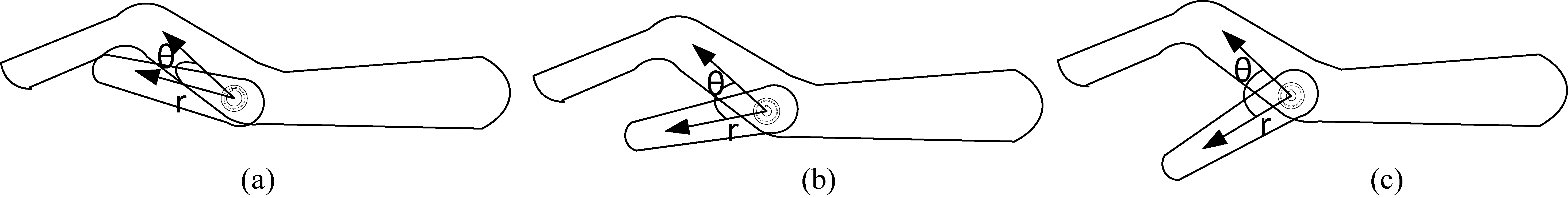
Three different positions of the thumb part with respect to the arm part is shown in the Fig. 2a–c. Figure 2a shows the minimum angle possible when the hand orthotic device is closed i.e. approximately 30 degrees and Fig. 2c shows the maximum angle possible when the device is opened fully to 90 degrees as the thumb of the hand cannot move beyond 90 degrees with respect to the fingers. The distance from the center of the gear to the point where the thumb force is maximum is r. Depending on the stages of therapy and the size and the weight of the object to be picked up, the
where
Modeling translates the problems from an application arena into mathematical equations where both theoretical and numerical analysis are useful for the original application. The mathematical modeling of the orthotic arm is therefore a necessary step so that it satisfies the scientific standards as per [24].
The skeletal model
The human hand has a highly segmented structure as shown in Fig. 3. Kinematic modeling of the human hand is the basic step in modeling the fingers. The kinematic structure of human hand has 27 degrees of freedom. The thumb has a different structure compared to the structure of other fingers.
Skeletal model of human hand.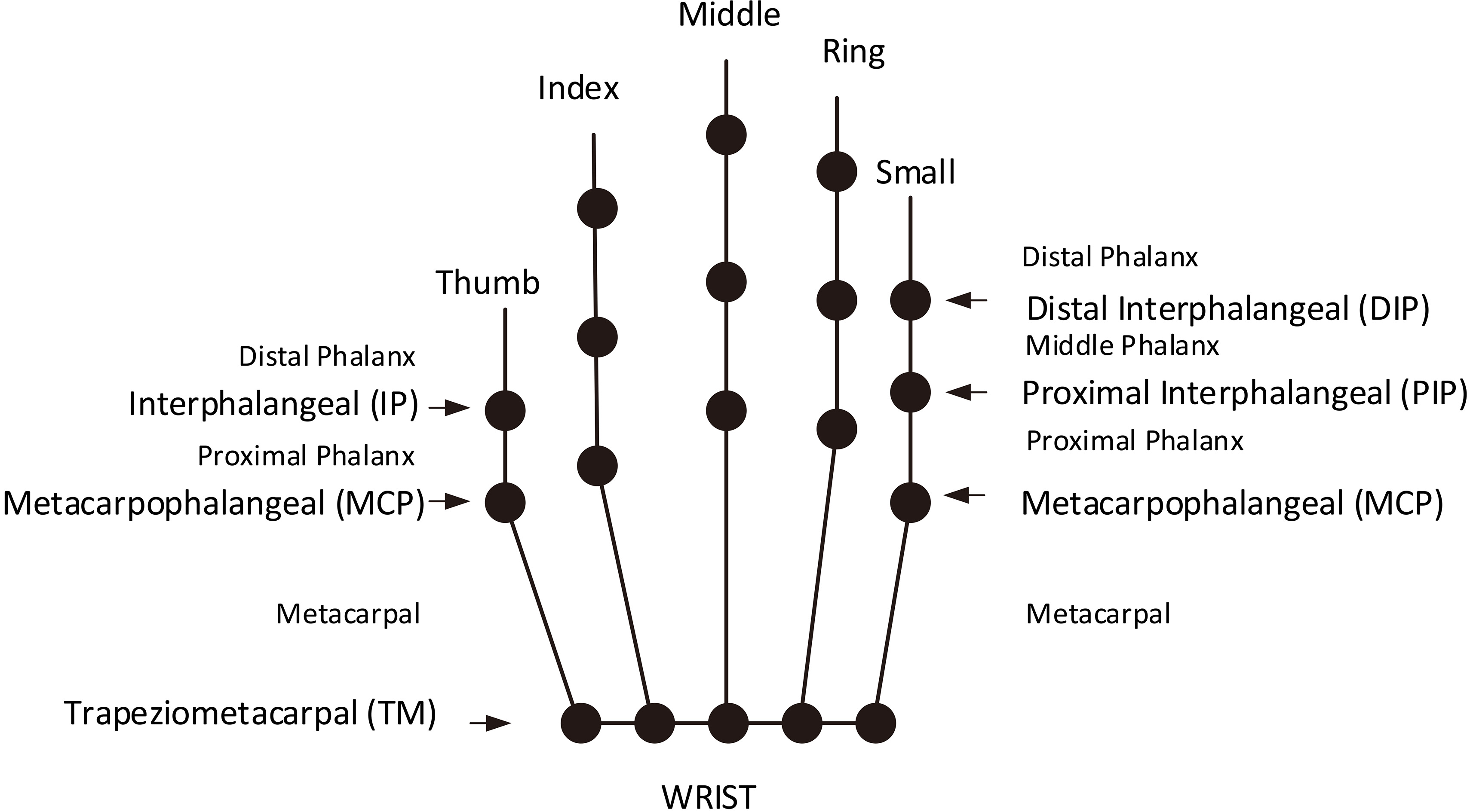
Skeletal model for our device.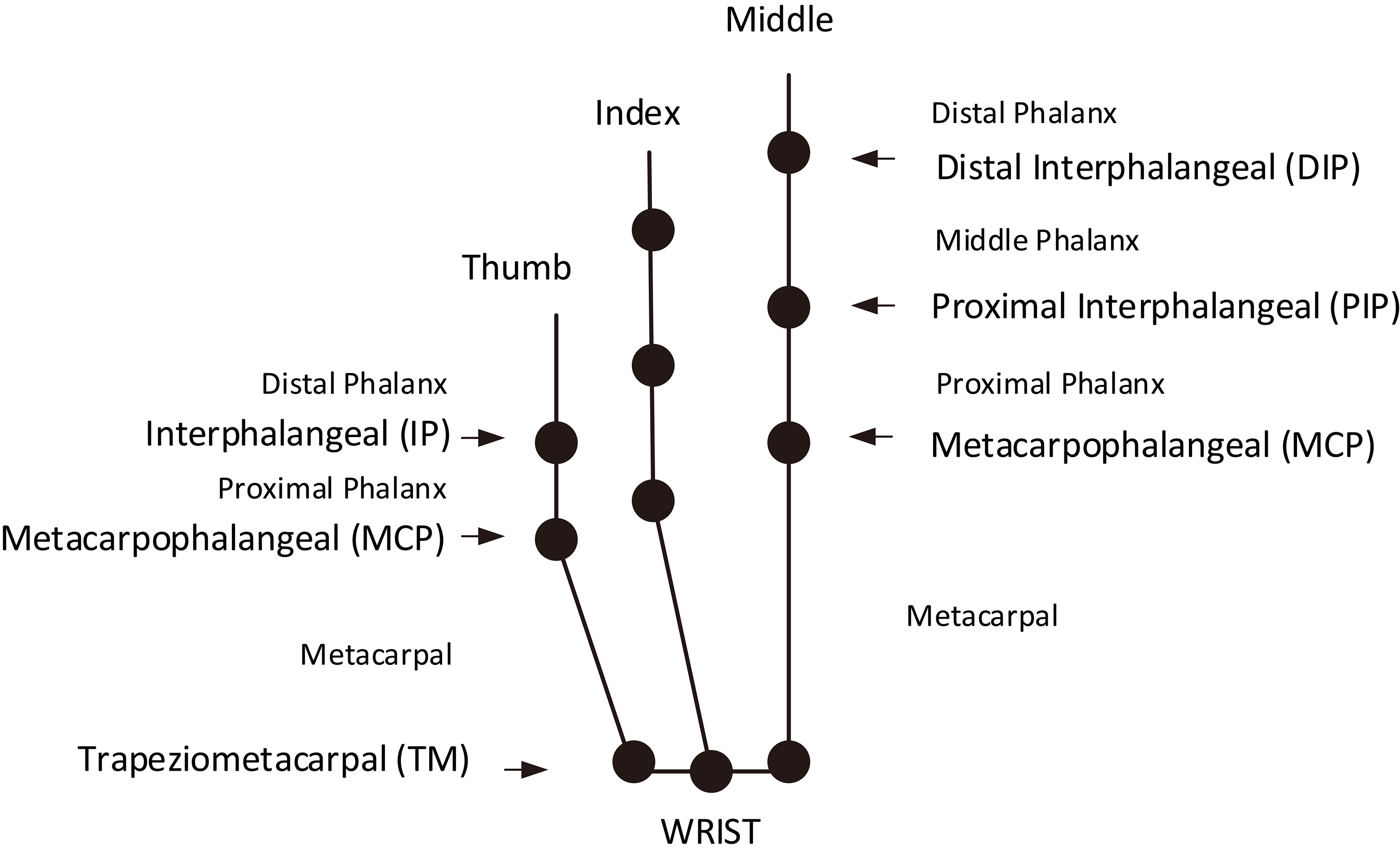
Plot of horizontal component vs vertical component.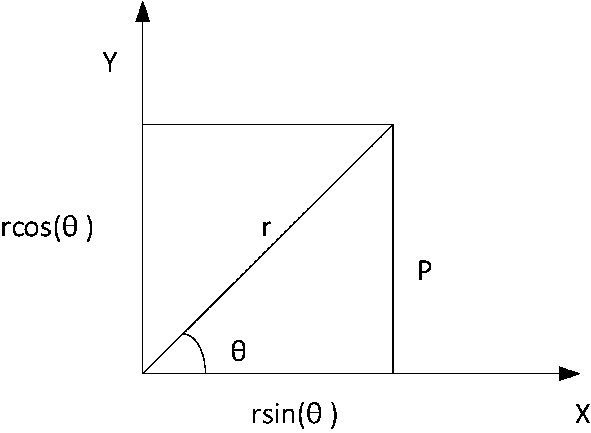
In case of four fingers other than thumb, the 3 joints in them are: Metacarpophalangeal (MCP), Distant Interphalangeal joints (DIP) and Proximal Interphalangeal joints (PIP), as shown in the Fig. 3. For both DIP and PIP, there is a single degree of freedom (DOF) and for MCP there 2 DOF respectively. However, for the thumb there is 1 DOF for end joint (END) and 2 DOF, one each for MCP and Trapeziometacarpal (TM) joints respectively [25]. The remaining DOF is due to translational and rotational motion of human arm. The orthotic arm in design stage involves the motion of opening and closing of palm and modeling is done with respect to these motion requirements. For a robot manipulator there is always a forward kinematic equation. In inverse kinematics the joint angles are derived from the position and orientation of the end effector. Compared to forward kinematics, it is much more strenuous to obtain a solution using inverse kinematics. To describe the kinematics of the model, Denavit-Hartenberg method [26] is used. It uses four parameters namely
This is the theoretical value of
where
where
These two equations are useful in confirming the mathematical model which was later used to find the response timings of the device opening and closing as explained in Section 5.
The orthotic hand is made with cheap thermoplastic material [27], which is covered with an outer cover to make it look visually appealing and straps are provided for fastening it to the arm as shown in Fig. 7. Firstly, a soft thermoplastic sheet was taken and then it would be placed it in hot water to make it soft so as to imitate the patient’s hand. Later the soft thermoplastic material would be placed and pressed against the patient’s hand to get it into a shape which can be later strapped and secured on the patient’s hand. The thermoplastic sheet would be cut accordingly to match the dorsal region of the patient’s hand and then the Velcro straps are attached to the device allowing it to be strapped onto the patient’s hand. To accommodate the servo motors two holes are made into the plastic and thus then are secured tightly using bolts and a nuts.
The proposed hand orthotic device design comprises of dual control interface with dual modes to control the device – GUI mode and switch mode, a device control unit, an actuator and the orthotic hand. The GUI mode helps in the self-actuation of the device. This is explained in detail in Section 4.1. The switch mode is useful in the initial stages of the rehabilitation. During initial stages of rehabilitation process, the physiotherapists and the patients need to learn how to use the device. Patients would also want to learn so they can use the device themselves when at home. The switch mode is very helpful for beginners to control the device without wearing in the arm and observe how it operates. It basically involves three switches which have a predefined operation. The first switch goes with the command to open the hand while the second gives the command to close the hand. These two switches are believed to serve the purpose of handling the device in the manual mode. The third switch was meant to execute a command which can trigger the device to open and close for a certain number of times as defined by the programmer or a patient or a physiotherapist. The commands generated by the user are serially transmitted to the device control unit (DCU) through the universal serial bus (USB). The DCU processes the commands and sends necessary control signals to the actuator. Figure 6 shows architecture diagram of the device.
Hand orthotic device architecture.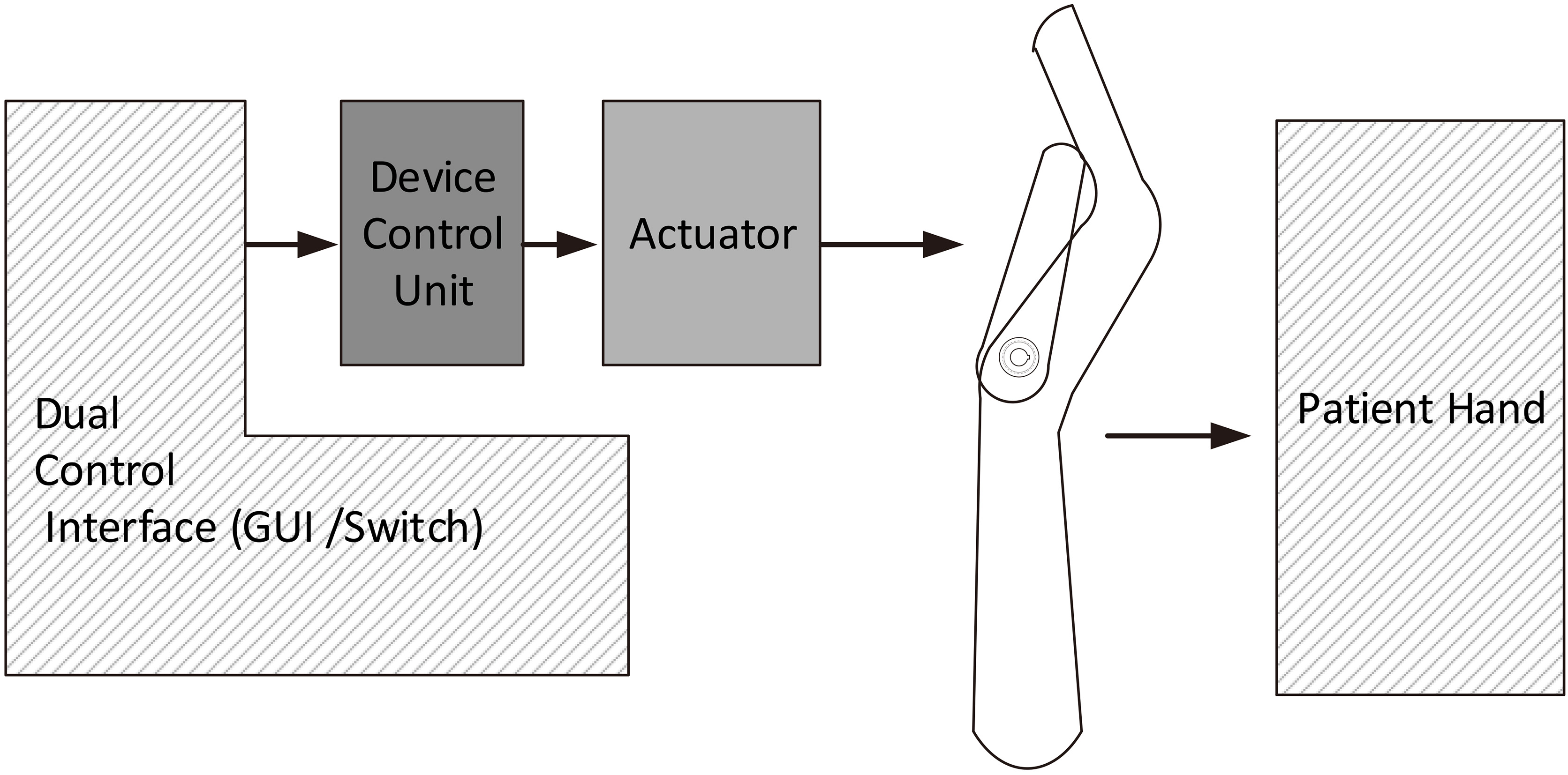
Different versions of the orthotic hand were shown in Fig. 7. The first one is hard plastic without any cover. The second and third orthotic devices are made of thermoplastic. The ones made with thermoplastic are better compared to the hard plastic ones as minor adjustments in the structure can be done manually while fastening the orthotic device to the user’s arm. Such adjustments are not possible in the orthotic devices made of hard plastic. The fabrication was done locally at a cost of approximately 5 USD.
Different range of device models.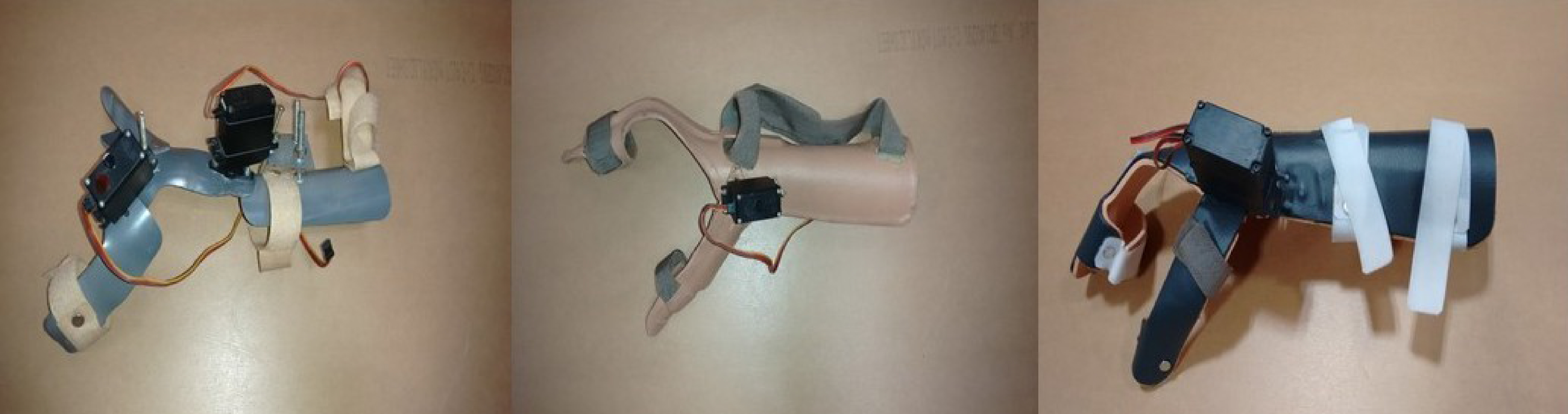
The need for a software arose from the physiotherapist’s difficulty to manage both the control mechanisms of the existing orthotic devices and the patient subjected to the orthotic arm. The software supports various functions and can undertake different types of motion using GUI. The orthotic device demands only two types of motion, the opening and closing of the palm using thumb, index and middle fingers with the help of thumb part as shown in Fig. 1. An actuator is connected to the orthotic device at the carpometacarpal joint to enable this movement. The major objective of the software is to control the servo motor in order to execute the required motion. In the GUI, we have two methods to operate which is manual or automated so that the self-actuation is possible. The manual mode is nothing but there are two buttons one intended to open the orthotic device while other intended to close the orthotic device. The user can click the buttons alternatively to mimic the abduction and the adduction of the hand. While, the automated method is nothing but the user can select how many times the device needs to open and close at a speed of his choice. The usage of this application enable the physiotherapists to interact more with the patient during the rehabilitation process since the control mechanism is entirely based on GUI. The working environment for initiating the GUI based control involves a personal computer or a laptop which is now easily available in hospitals and rehabilitation centers, Arduino – an open source microcontroller board and a servo motor. The solution developed here is highly cost effective as compared to the existing sophisticated and high level prosthetic technology as given in the cost analysis section.
Table depicting various GUI commands
Table depicting various GUI commands
The basic step in initializing the software is to enable the connection between the application and the Arduino (DCU). The CONNECT tab provided in the GUI establishes the required connection. Table 1 describes the functions of various tabs included in the GUI. The angle of opening and closing of the hand can be varied according to the user needs. In the current design three angle options have been included which is achieved by using the LOW, MED, and HIGH tabs. In the LOW angle mode the arm opens and closes up to 40 degrees, 60 degrees in the MED angle mode and 90 degrees in the HIGH angle mode. The MED tab value can be edited for any angle between 40 and 90 degrees. In case of emergency where the physiotherapist or the patient want to switch off the device immediately, the EMERGENCY STOP tab can be used. This is to ensure safety of the users.
The speed of the actuator is controlled using Pulse Width Modulation (PWM) technique in Arduino. The angle of motion is controlled by changing the maximum position to which the actuator should move from its initial position. The application has an additional drop down style tab through which the number of repetition of a particular motion can be selected. The predefined numbers are 2, 3, 4, 5, and 10. The above numbers can be customized as per the user requirements. It also has a display area which displays the speed mode, angle mode and the current operation done by the application. The software is packaged as a standard windows application which works across all windows versions starting from Windows XP. A sample of the developed GUI used for controlling the orthotic device is shown in Fig. 8.
Computer based GUI.
Trajectory plot for various lengths.
The simulations for various case conditions are carried out to evaluate the mathematical modeling of the device. To obtain more clarity three different sizes of thumb part of the orthotic hand were assumed, which have their lengths as 13 cm, 13.4 cm, and 16 cm respectively. For these three lengths, the initial step is to vary
Table explaining the legends used in Fig. 10a and b
Table explaining the legends used in Fig. 10a and b
(a, b) Trajectories for device closing and opening for various test cases.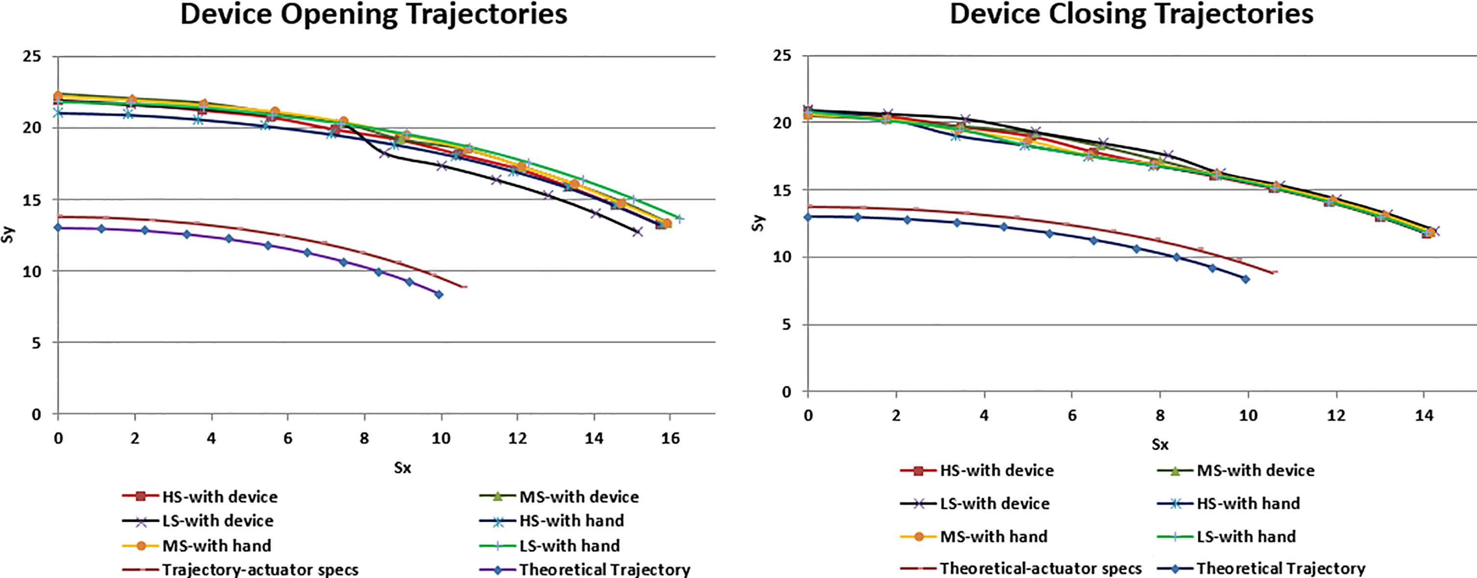
The evaluation of the designed hand orthotic device was conducted in two phases in the laboratory and in the medical setting. The initial phase of testing had two types of test. The first type is testing the device without the user/volunteer, which is called ‘device-only’ test. The second type of test is conducted at the research lab with volunteers in self-actuating mode. The GUI is used for both types of testing and these results are shown in Fig. 10a and b and this test is carried out to find out the response timings for opening and closing of the device in two cases. In the first case the tests were carried out in a stand alone mode without attaching it to the volunteer but in the second scenario the tests were carried out by attaching the orthotic device to the volunteer. The response time here is defined as the duration of time taken by the device to respond to an issued command through the interface.
At first the response timings for device-only case was measured where the actuator load is the device alone. Next, the response timings when the volunteers used the device was measured for which each of their hand along with device acted as actuator load. Using the Micro-Controller Unit (MCU) response timings were found out for the angles ranging from 40 degrees to 90 degrees in step of 10 degrees for both device opening and device closing. A value little higher than 30 degrees is chosen to begin the tests as the minimum
Device-only load tests for HS, MS and LS with 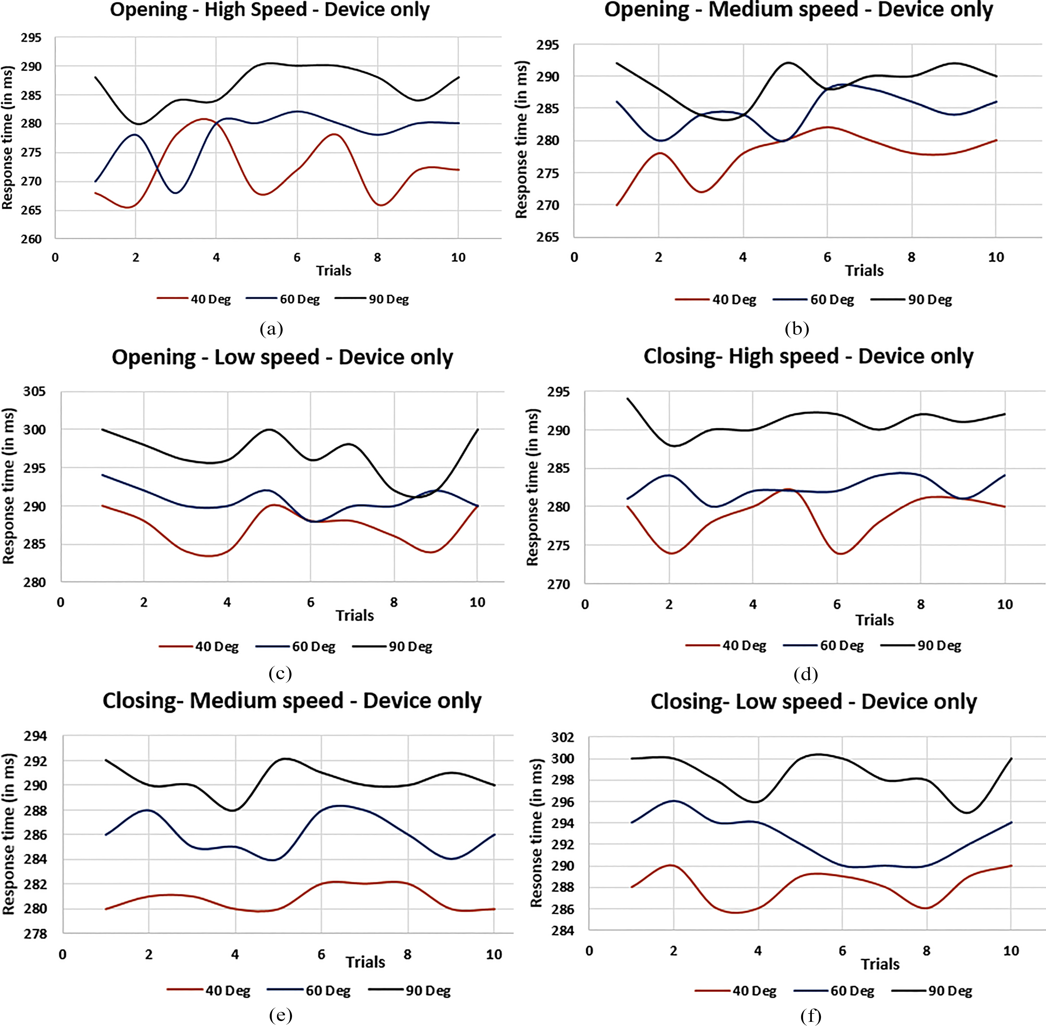
Figure 11a–c shows the response timing plots for the device-only load cases under device opening conditions. Figure 11d–f shows the same for the device closing cases. In these response timings plots, even though crests and troughs due to the difference in response timings, they are not that much significant for the intended application as plot is in milliseconds scale. The tests were carried out with other angles but due to the repetitive nature of the graph they were not presented here. In addition, ten trials were conducted for each of the volunteers and that is too many plots to show here. The trajectories for the response timings in Fig. 10a and b for all the volunteers and trials taking the average for each case were already shown.
The second phase of testing was carried out at the Physical Medicine and Rehabilitation Department of Amrita Institute of Medical Science (AIMS), Amrita Vishwa Vidyapeetham University, Cochin, Kerala, India. The doctors and physiotherapists used the orthotic device and tested its functions before administered to the patients. They simulated clinical activity with both the switch and self-actuation modes. The software application installation was taught to them and all the GUI tabs’ operations was explained to them. Two doctors and two physiotherapists tested both the GUI and the hand orthotic device. All the four clinical staff responded by rating both these as best when they were asked to rate on the scale of 1 to 5, 1 being worst and 5 being the best. The parameters on which they rated the interface and the orthotic device are the ease of use, concise and compact control buttons, appearance, ability of the device to quickly respond to the given command from the interface, comfort on wearing the device etc.
The abduction and adduction tests by patients suffering from partial paralysis of the hand in both the switch and self-actuation modes were carried out at the rehabilitation center. The orthotic device was designed with support for the thumb, index finger and the middle finger since these three fingers play vital role in performing abduction and adduction operations.
Illustrative images of device actuation tests performed in the lab.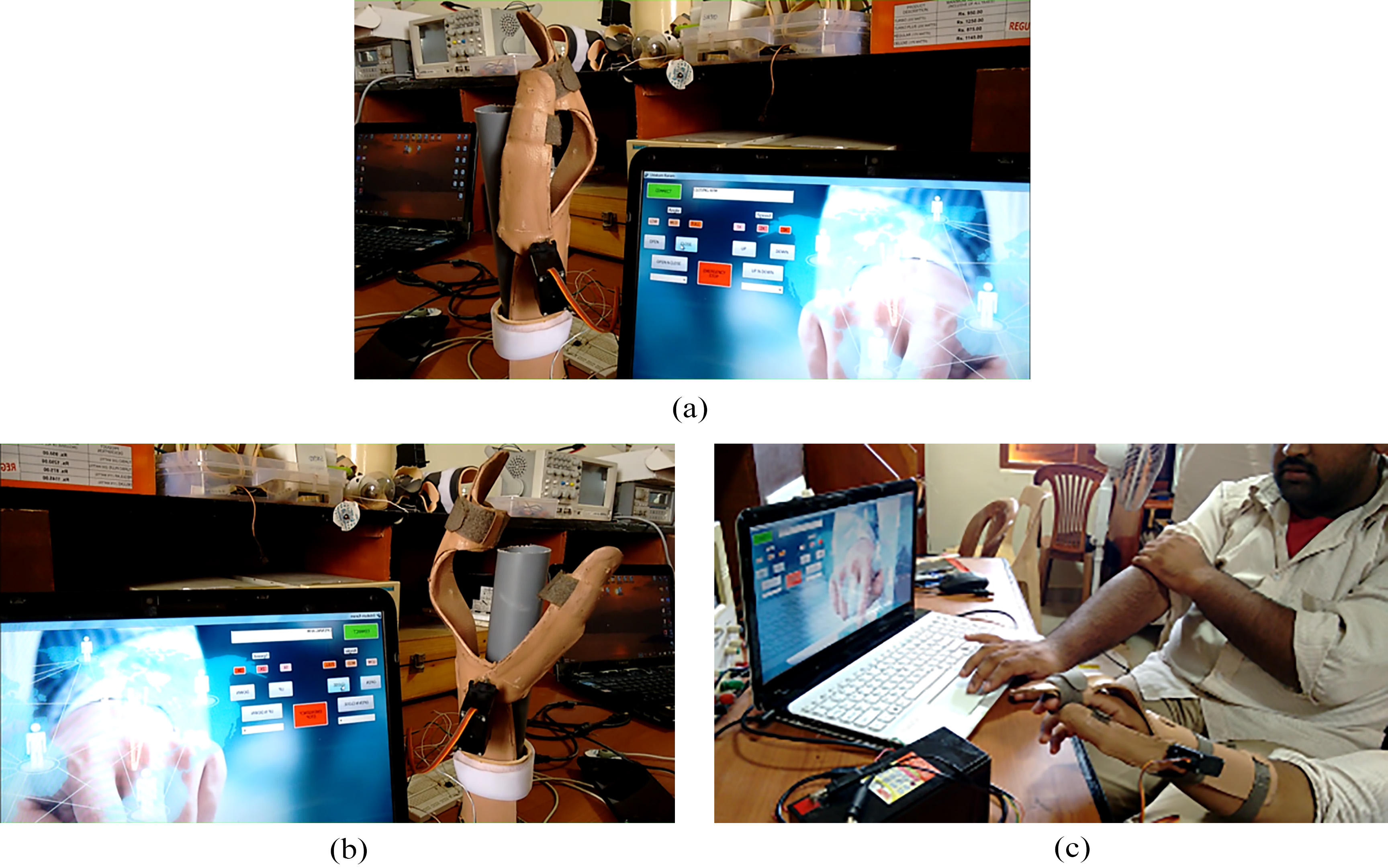
Illustrative images of tests performed in the lab with volunteers.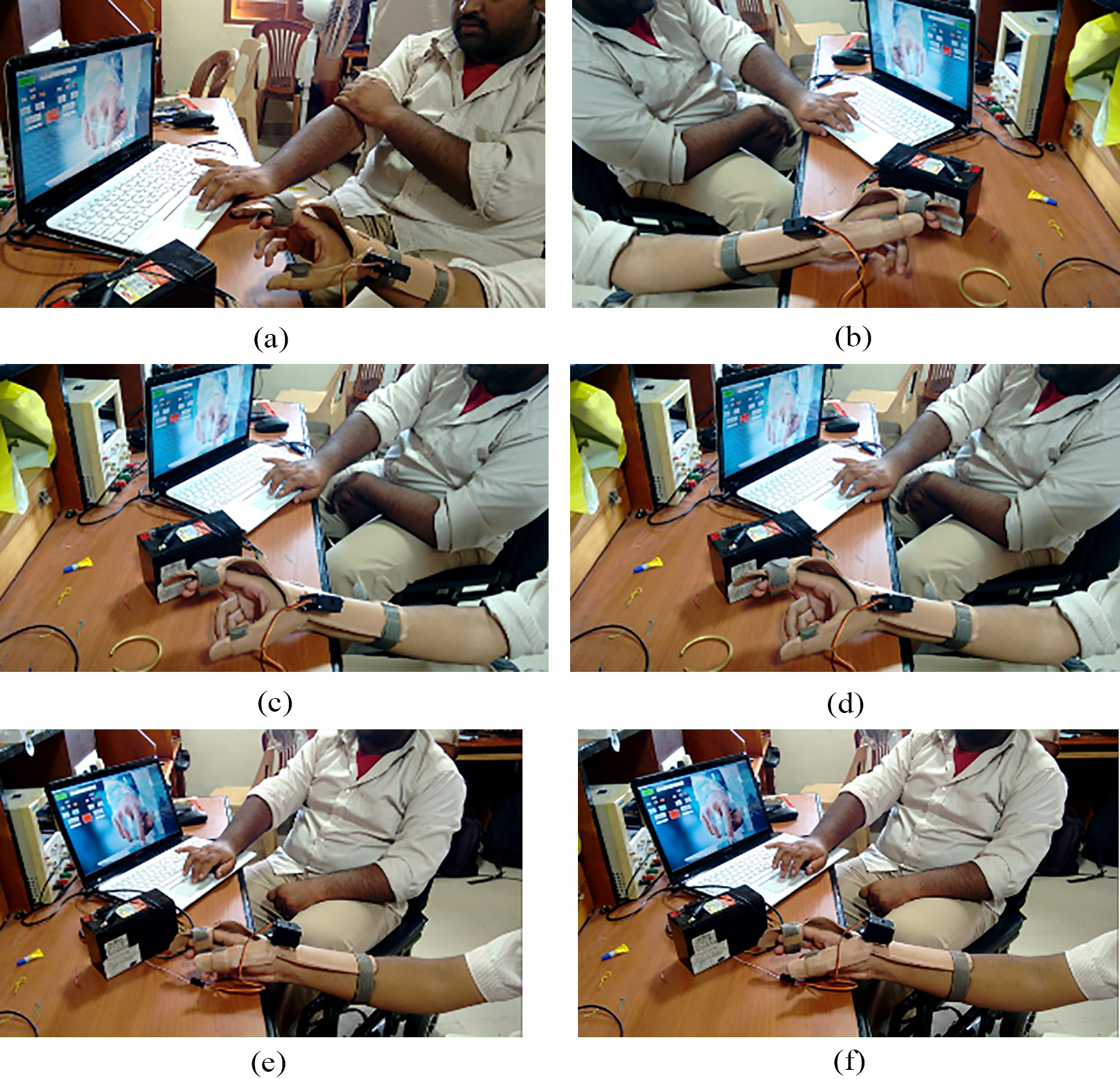
The tests that were performed was tabulated as follows in the Table 3.
At the Rehabilitation Centre four stroke patients volunteered to test the orthotic device. The goal of this clinical activity is two fold. The first one is to make sure the patients perform a basic pick and place of the objects. The second is to hold a pen and write. The procedure for the test is done as follows: Initially, without attaching the device, the patients were asked to pick, place and displace various objects used in daily life like a pen, small rod of reasonable dimensions, irregular plastic pieces, torch light, steel jar, plastic glass and a car steering model. As next test, they were asked to hold a pen and write, without the administration of the device. In all these scenarios, the patients could not hold any of these objects. In addition, could not hold the pen and write. Later the hand orthotic device was fastened to the hand of all the patients. After 3 to 4 hours of training and familiarization with the device, the patients were asked to again pick an object and place them nearby. They could the pick and place with ease as the actuation of the device assisted them in gripping, grasping and displacing the objects. They were also able to hold the pen and write on a piece of paper. Doctors and physiotherapists acknowledged these tests to be successful since the patients were able to perform the pick and place operations and were able to write using a pen. According to the feedback given by them, the usage of the product increased their confidence level and also the repeated testing procedure gradually decreased the initial difficulties. The device-only tests performed in the lab are shown in Fig. 12a and b. The images in Fig. 13a–f show the hand orthotic device being tested with some of the volunteers at the research lab and the rehabilitation center. Images in Fig. 14a–i show the device used by patients at the Rehab. Center. Initially the slight variations in the response times in the graphs as shown in the Fig. 11 is because of the resistance featured by the patients as the device is new to them and with the continuous usage they get habituated to the device and its operation.
Illustrative images of tests carried out with patients at the rehabilitation center.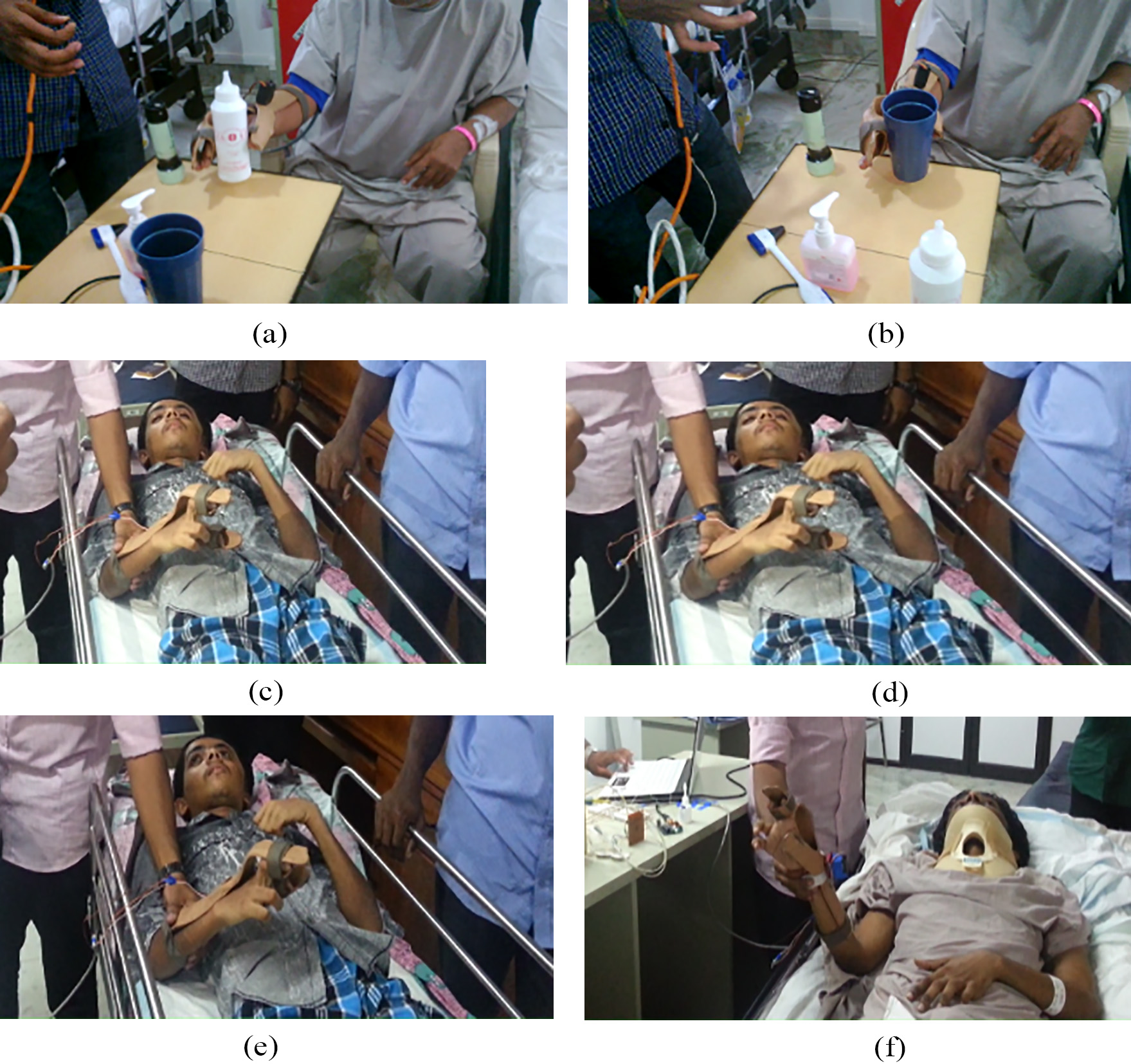
Many of the devices designed and tested for hand exoskeleton [20, 22, 23, 28, 29, 30, 31, 32] similar to device presented in this paper were referred for the purpose of cost analysis. To be fair in cost analysis, only the cost of fabrication of the mechanical parts in these referred prototypes or products are considered for comparison. Even though the referred designs in these research papers do not discuss about the cost of implementation, with knowledge in mechanical design and fabrication, the number of mechanical parts that is required to build the prototypes in each of the referred designs is estimated first. The other costs including control, programming, licensing etc. are not considered as they may vary depending on the nature of the control method, operational cost etc. These mechanical parts range from 17 to more than 100 in number. Based on the number of parts, hardware design and based on the complexity of the design we approximately estimated the cost of these prototypes ranging from USD 250 to USD 1000. This estimate is only for the mechanical parts. For the our proposed device there are only 7 mechanical parts and costs about USD 12 only to fabricate them.
Conclusion
The research project was aimed towards the design and development of low cost, efficient, user-friendly hand orthotic device to aid physiotherapists and patients of hand paralysis in the rehabilitation process. The mathematical modeling presented in Section 3 takes into account the initial resistance offered by the patients to opening and closing their palm using their thumb. This is mainly due to the device that they have not seen before and the fear that it might cause some pain or discomfort to them. It was found that this resistance decreased as the patients started spending more time using the device. This was confirmed by the physicians and physiotherapists at the rehabilitation center where the tests were performed with the patients wearing the device. The orthotic device is fabricated with cheap thermoplastic material. It is designed in such a way that it is easy and simple to fasten to the arm as per the suggestions by the medical experts at the rehabilitation center at AIMS medical school. As per the professionals at the fabrication facility where our device is fabricated, the durability of this device is five years.
The inclusion of a dual control – GUI/Switch as a control mechanism further improved the ease of usage of the orthotic device by reducing the complexity involved in the rehabilitation process. The GUI included an application package which provided appropriate command to the actuator of the orthotic device through a MCU. The work also included a testing and evaluation phase in which the hand orthotic device was tested on paralyzed patients at the rehabilitation center at AIMS and research volunteers in the authors laboratory. The experimental section details the test results and the mathematical modeling of the device is validated using the response timings for the device-only and device with user’s hand cases. The results indicate that the implemented hand orthotic device design can be used as a solution for situations involving the need for low cost, fast and less complex rehabilitation techniques in patients with hand paralysis due to stroke and spinal cord injuries. There are a few complications that were have to be met initially. Since the researchers are mainly based on engineering background a lot of research and follow ups has to be carried out to carefully and closely understand the design of the orthotic device which suits the requirement. The fabrication of the device also took considerable amount of time which added to the delay in the research. At the end, with the help and cooperation extended by the physiotherapists and the volunteers, the research was carried out fruitfully.
Footnotes
Acknowledgments
The Humanitarian Lab and the Department of Electronics and Communication of Amrita Vishwa Vidyapeetham, Amrita School of Engineering, Amritapuri, Kollam were thanked for providing all the necessary lab facilities and a highly encouraging work environment which was a key factor in the completion of the project. Dr. Ravi Sankaran, Asst. Professor, Department of Physical Medicine and Rehabilitation, Amrita Institute of Medical Sciences was also thanked for extending his help and support for testing the device with the patients.
Conflict of interest
None to report.