
Abstract
BACKGROUND:
The aim of a robotic exoskeleton is to match the torque and angular profile of a healthy human subject in performing activities of daily living. Power and mass are the main requirements considered in the robotic exoskeletons that need to be reduced so that portable designs to perform independent activities by the elderly users could be adopted.
OBJECTIVE:
This paper evaluates a systematic approach for the design optimization strategies of elastic elements and implements an actuator design solution for an ideal combination of components of an elastic actuation system while providing the same level of support to the elderly.
METHODS:
A multi-factor optimization technique was used to determine the optimum stiffness and engagement angle of the spring within its elastic limits at the hip, knee and ankle joints. An actuator design framework was developed for the elderly users to match the torque-angle characteristics of the healthy human with the best motor and transmission system combined with series or parallel elasticity in an elastic actuator.
RESULTS:
With the optimized spring stiffness, a parallel elastic element significantly reduced the torque and power requirements up to 90% for some manoeuvres for the users to perform ADL. When compared with the rigid actuation system, the optimized robotic exoskeleton actuation system reduced the power consumption of up to 52% using elastic elements.
CONCLUSION:
A lightweight, smaller design of an elastic actuation system consuming less power as compared to a rigid system was realized using this approach. This will help to reduce the battery size and hence the portability of the system could be better adopted to support elderly users in performing daily living activities. It was established that parallel elastic actuators (PEA) can reduce the torque and power better than series elastic actuators (SEA) in performing everyday tasks for the elderly.
Introduction
Robotic exoskeletons help users of impaired gait to perform the activities of daily living (ADL) independently. According to Roberts et al. [1], there are more than 617 million people aged 65 or more are estimated worldwide, which is 9% of the total population and the number will keep increasing. The gait of the elderly significantly differs from the young healthy gait during locomotion [2, 3]. One of the major causes of the accidental deaths in the elderly are the frequent falls [4] and which is directly linked with the change in the movement of the gait [5]. Several assistive exoskeletons are described in the literature, ReWalk [6], Indego [7], Ekso [8], HAL [9], Mina [10], Mind walker [11] and Rex Bionics [12]. These assistive exoskeletons can provide a matching torque angular profiles of a healthy individual to assist the impaired gait users. Some of the exoskeletons developed are light-weight but require crutches to maintain balance and hence compromise on the insufficient actuation of the joints. Rex, on the other hand, does not require any crutches to maintain balance but it is one of the heaviest assistive exoskeletons available to date. This paper developed an optimization strategy for choosing the optimal motor and transmission systems combination along with the optimized stiffness values of the elastic elements for designing an assistive exoskeleton robot with the objective of minimizing its total weight and power to enhance the portability of the device so that user can independently perform ADL. Considering the human motion characteristics of a healthy human, it will determine the optimal actuation system for series and parallel elastic actuators.
Several studies that use the concept of series and parallel elastic elements in wearable robots have been recorded [13, 14, 15, 16, 17, 18, 19, 20]. However, fewer applications of parallel elastic actuators (PEA) were reported as compared to series elastic actuators (SEA). An elastic element e.g., a spring can help lower the peak torque and power requirements over the range of motion of the joint. The design optimization exists for systems such as engine optimization and enhancive/assistive exoskeletons for rigid systems, in this research, the effect of the introduction of the elastic elements on the exoskeleton joint optimized design will be studied. It was found that adding a parallel spring can reduce the peak torque and power at the lower limb joints [18, 21]. On the other hand, a series spring can bring benefits in terms of power and energy consumption at the ankle joint [22, 23]. In order to achieve the optimum results, the stiffness of the spring needs to be adjusted for a particular parameter of interest [24]. The spring parameter optimization to reduce power and energy requirements were investigated by several studies and reported some of the spring optimization criteria [22, 25, 26, 27, 28, 29]. The optimal stiffness of the spring based on peak power and energy consumption was studied by [30]. It was found by Grimmer, Eslamy and Seyfarth [22] that the spring stiffness should be adjusted for the case of SEA with respect to the minimum energy at the hip and knee joint and minimum peak power at the ankle joint. However, the approach previously used [22, 30] was based on powered prosthetic devices. A comparison among different configurations of the SEA was established [31]. In these studies, the optimization process considered only the task requirement without involving the actuator dynamics. The motor and transmission systems full capabilities need to be exploited in order to obtain lightweight and power-efficient actuator systems.
It has been recorded in the findings described above that a spring can reduce the high torque and power demand on the motor. But what should be the best approach to optimize the stiffness of the spring for assistive exoskeleton applications? With the optimized elastic elements, what should be the optimal process for the selection of the motor and the transmission system? In this paper, the optimum actuation system will be realized by choosing the best combination of motors and transmission systems as well as employing the optimum spring stiffness. It will develop a novel technique to optimize the stiffness of the spring for assistive exoskeleton applications. This will help the designers to choose PEA and SEA with their stiffness values and equilibrium angles for lower limb exoskeletons which consist of the hip, knee and ankle joints. Furthermore, with the optimized elastic elements, a novel optimization approach for the motor and transmission systems for assistive robotic exoskeletons will be developed that requires a careful consideration among different design parameters. There must be an acceptable level of compromise that should be made in one variable to achieve better results for another variable. This will promote more lightweight, compact and power-efficient actuators. Therefore, an optimization approach to design the elastic actuation systems of assistive robotic exoskeletons is essential.
Methodology
Exoskeleton gait data
The human gait data of a healthy subject was collected and analyzed for sit to stand and level ground walking. Procedures involving experiments on human subjects are done in accord with the ethical standards of the Committee on Human Experimentation of the institution in which the experiments were done or in accord with the Declaration of Helsinki of 1964 and its later amendments or comparable ethical standards. Approval body was MaPS and Engineering joint Faculty Research Ethics Committee (MEEC FREC), University of Leeds (Ref. No. MEEC 15-004). These two types of maneuvers represent the basic tasks of elderly people to perform activities of daily living (ADL) independently. The gait data of a healthy human subject was acquired by placing markers at certain points on the subject while several cameras were recording the positions of the markers. An informed consent for the experiment was obtained from the subject. Five trials were obtained by the subject for each of the manoeuvres. The points where markers were placed on the lower limb of the subject were described as the common points between the user and the exoskeleton and therefore, the kinematic data of these points will be used in the dynamic model of the exoskeleton. The exoskeleton geometric and inertial parameters were considered to estimate the kinematic and kinetic model of the exoskeleton. During the calculation of the weight of the user, the total weight was divided into the upper part and the lower part of the body. The weight of the upper part was considered to be a point mass located at the upper part of its centre of gravity. The mass of each lower part of the body was added at the centre of gravity of each respective exoskeleton link in the dynamic model of the system. During the calculation of the total weight of the exoskeleton, the mass of the user was subtracted from each exoskeleton link.
Design requirements
The exoskeleton was intended to be designed for elderly people that can provide 50% support to its users. Three degrees of freedom (DOFs) were actuated i.e. hip flexion/extension (HFE), knee flexion/extension (KFE) and ankle dorsi-plantar flexion (ADP). With these actuated DOFs, sit to stand and level ground walking could be performed. A user of 100 kg was targeted as the maximum body weight. The basic requirements were obtained from the Rex Bionics exoskeleton. The optimization of the exoskeleton actuation system was based upon minimizing the total weight, the total power consumption and supporting the maximum allowable user weight. The torque and power requirements obtained from the collected data are listed in Table 1 for the hip, knee and ankle joints. This table is obtained by using the joint position data from motion capture experiment. Exoskeleton links dimensions were introduced to obtain the joint kinematics. The inertial parameters of the exoskeleton were included in the joint kinematics to obtain the torque and power requirements of the joints. This data of a healthy person will be used as a reference in order to match the torque-angular profiles of the exoskeleton in order to support the elderly. The knee joint during the stance phase was assumed to be fixed and the double support stance phase has not been considered.
Design requirements of assistive robotic exoskeleton actuation system at hip, knee and ankle joint
Design requirements of assistive robotic exoskeleton actuation system at hip, knee and ankle joint
The torque and power requirements were derived similar to [32] for motor and the strain gears. For springs in series and in parallel, it was evaluated from [21]. But in contrast to [21], rotational models for SEA and PEA were analyzed. In the developed model, motor efficiency and inertia has also been considered.
Modelling of electric motor
The total torque applied at the rotor of the motor
In Eq. (1),
Where
The power consumption of the motor can be obtained from Eq. (5).
Where
For any given joint torque and power, the torque and power required by the motor must lie within the allowable limits of the motor given by its winding, temperature and current line.
Equation (6) shows the torque required by using harmonic drives.
Where
The geometrical equation using an inverted slider Ball screw mechanism is illustrated in Eqs (8) to (10).
where “
Schematic of the Ball screw crank mechanism with a series spring.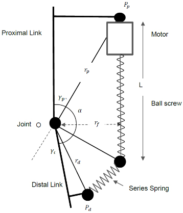
(a) Schematic of SEA model. (b) Schematic of PEA model.
The basic advantage of adding a series spring is to reduce the amount of power required by storing the energy and reusing it during power-demanding moments. Although SEA can reduce the power demand of the motor, it does not reduce the torque requirement of the motor [33]. Figure 2a represents the schematic of the SEA. Motor power can be obtained from Eq. (11) as
The required peak power of the SEA is calculated as
In order to estimate the required energy consumption the RMS power is used given by Eq. (13).
Where
PEAs are used to reduce the amount of torque required, thus reducing the requirement of a large transmission system. However, it also gives benefits in terms of power requirements. The schematic of PEA is shown in Fig. 2b. The power requirement of the PEA can be given as,
Where
The peak and rms value of torque and power can be calculated using Eqs (16) to (19)
In Eq. (17),
The optimized stiffness for series spring
Where
After incorporating the exoskeleton geometric and inertial parameters, the stiffness of the spring was selected starting from 0 to 2000 Nm/rad and the equilibrium angle from 0 to 360 (deg). The algorithm then computes the kinematic and kinetic variables at a given joint for all the maneuvers.
It should be noted that the spring stiffness value and the equilibrium angle were considered to be fixed and do not change during sit to stand operation as well as swing and stance phase of the gait cycle, therefore, similar value for spring stiffness and equilibrium angle was used throughout for each of the three maneuvers. The same procedure is repeated for all lower limb joints i.e. hip, knee and ankle to calculate the optimum spring stiffness at each of the joint.
After integrating the motors and the transmission systems with the desired springs of appropriate stiffness, the optimal elastic actuation system was evaluated using the optimization algorithm for elastic actuators. The algorithm determines the optimal actuation system initially at the knee joint and then proceeds towards the hip and ankle joint and it continues to repeat this cycle until the optimized elastic actuators for the case of PEA or SEA were revealed at each of the three joints. As the algorithm computes the total weight and power of the system, it assumes the lightweight actuators at the hip and ankle joint while performing the optimization at the knee actuator.
For a given joint, the optimization algorithm computes the kinematic and kinetic requirements of the system depending upon whether the actuation system consisted of PEA or SEA with the given exoskeleton geometrical and inertial parameters. For the case of PEA, it uses Eq. (16) and for SEA, it uses Eq. (12) with the optimum spring stiffness and equilibrium angle. It should be highlighted that the stiffness and equilibrium angle of the spring were selected with the spring optimized for the multi-factor criterion. After the kinetic model was obtained by incorporating the type of the elastic system, the algorithm selects a motor from the list at a given joint while assuming the light weight actuators at the other joints. Similarly, the transmission system was also included and the required motor torque, velocity and acceleration were evaluated using the transmission system model specified previously. The required torque, velocity and acceleration of the motor were then compared with the torque speed curve of the motor to verify if the given candidate elastic actuator satisfies the motor limits. If the given candidate elastic actuator does not satisfy the motor limits, it moves to the next candidate in the list but if it satisfies, a score is calculated for that candidate elastic actuator using Eq. (21).
Where
Different weightage was given to each parameter and the normalized values of these variables were included in the objective function. A negative weightage was given to the weight and power in the objective function since a smaller value for these variables was desired. After estimating the score of a given candidate elastic actuator, it moves to the next motor and repeats the above procedure to calculate the score for the next particular candidate actuator. After computing it for all motors, it moves to the next transmission system in the list until all the motors and the transmission systems are exhausted. Lastly, it determines the elastic actuation system with the highest score calculated from the objective function.
The elastic actuator with the highest score will be the most optimized actuator at this phase at a given joint i.e. knee joint since the algorithm was initially applied at this joint. The above procedure is repeated at the ankle joint by taking the knee actuator from the previous step and hip actuator as the previously assumed one. Similarly, the optimized hip actuator was assessed using similar procedure as described above with the knee and ankle actuator updated from the previous steps. The algorithm keeps on repeating until all actuators were obtained similar to their previous iteration at each of the lower limb joints.
A model of a lower limb exoskeleton developed in SolidWorks was analyzed using SolidWorks motion analysis toolbox to perform the kinetic analysis at the lower limb joints. The developed model in SolidWorks was exported to SimMechanics, an environment within MATLAB to realize the system using actual physical components. The actuation system of the exoskeleton was first built in a virtual environment using physical components available in SimMechanics. It was then further implemented in an experimental prototype. The model consisted of a hip part, the thigh part, the shin part and the ankle and foot. Both sit-to-stand and level-ground walking was implemented in this model. The obtained data mentioned in Section 2.1 was fetched in the system to obtain the torque and power requirements at each of the joints. The motor and the series and parallel springs were also added at the hip, knee and ankle joint. The effect of transmission systems was also included after obtaining the torque and power at each of the joints.
Results
Optimization of spring stiffness
The results of the spring stiffness obtained for different minimization criteria are tabulated in Table 2. The optimized value can be found between 20 to 25 Nm/rad at the hip joint for the case of PEA and equilibrium angle between 13 to 16 deg. The stiffness value for the knee was observed to be higher for peak torque and power cases. At the ankle joint, the torque minimization case favored higher stiffness values whereas the power minimization case indicated a lower value. The overall optimization suggests a smaller value of the spring stiffness for PEA. The spring stiffness optimization in SEA recorded a higher value, especially for knee and ankle joints. For the knee joint, the spring stiffness value did not change.
Optimal spring stiffness values for different minimizing criteria for torque and power at hip, knee and ankle joint
Optimal spring stiffness values for different minimizing criteria for torque and power at hip, knee and ankle joint
Hip
Torque and power requirements at the hip joint during sit to stand (SS), swing (SW) and stance (ST) phase of the gait for PEA, SEA and rigid actuation system. The values of the variables 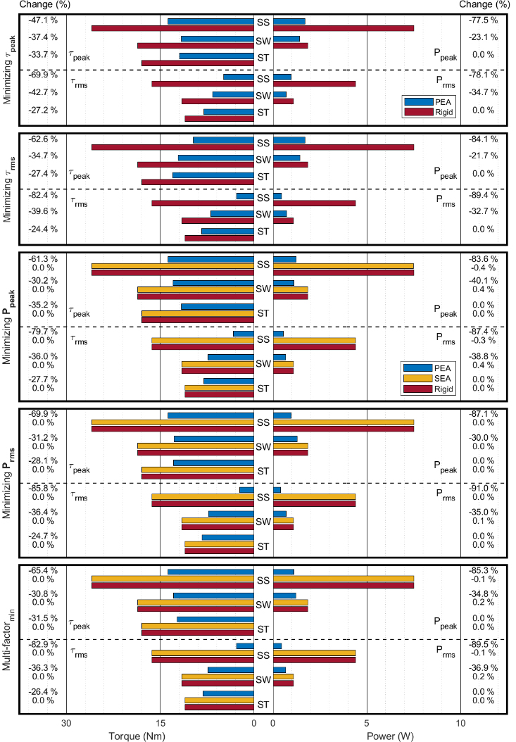
Torque and power requirements at the hip joint during sit to stand (SS), swing (SW) and stance (ST) phase of the gait for PEA, SEA and rigid actuation system. The values of the variables 
The torque and power requirements at the hip joint using PEA and SEA as compared to the rigid actuator is elaborated in Fig. 3. All four variables of interest are shown during each of the minimization criteria. When optimizing the spring stiffness for the case of
The stiffness of the spring for different cases of minimizations at the knee joint is shown in Fig. 4. At the knee joint, for the case of minimizing
Ankle
At the ankle joint, PEA increased the amount of torque and power during sit to stand and swing phase but decreased a considerable amount during stance phase of the level ground walking. The peak value of torque and power was also observed to be in the stance phase. When minimizing the ankle joint for the case of
Torque and power requirements at the knee joint during sit to stand (SS), swing (SW) and stance (ST) phase of the gait for PEA, SEA and rigid actuation system for various minimization criteria. The values of the variables 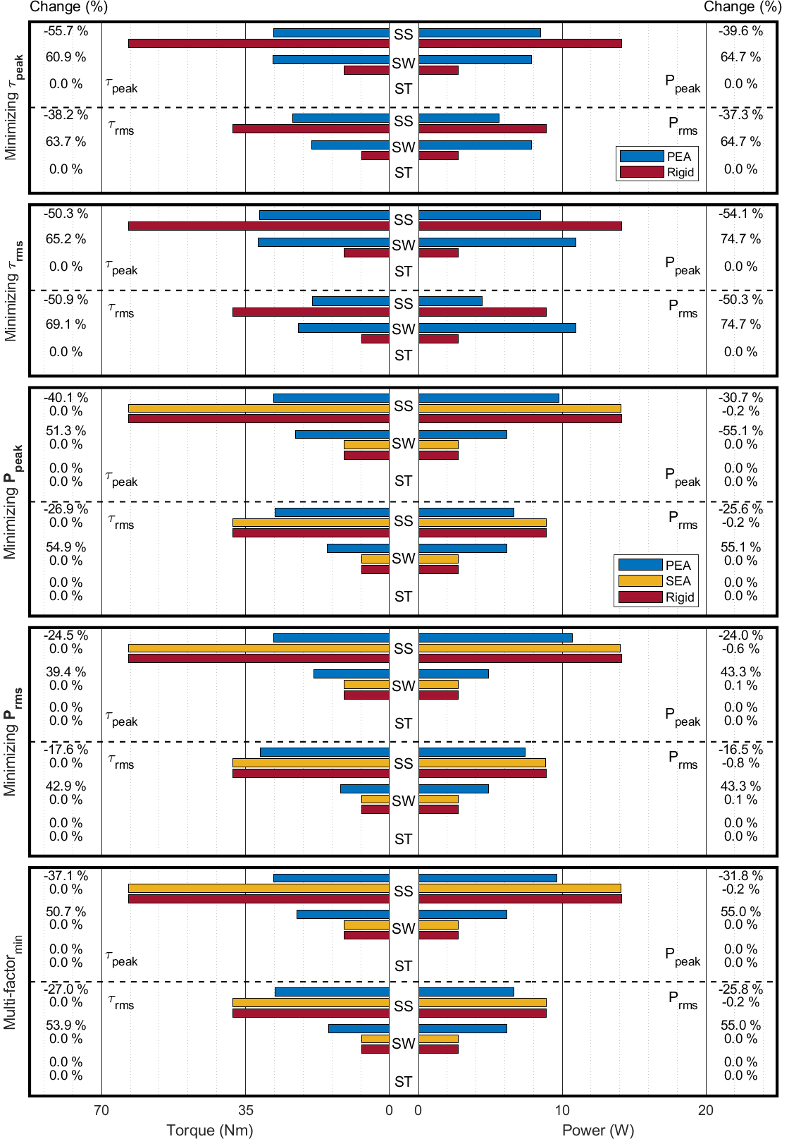
Torque and power trajectories at the hip joint during sit to stand (SS), swing (SW) and stance (ST) phase.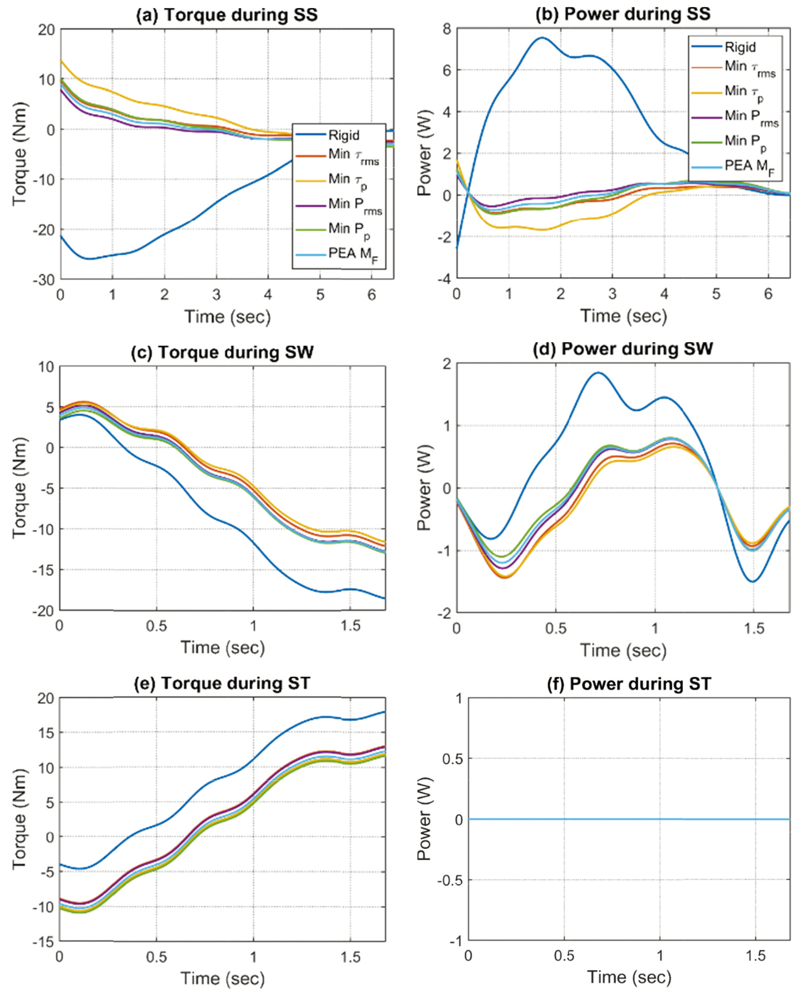
Torque and power trajectories at the knee joint during sit to stand (SS), swing (SW) and stance (ST) phase.
Torque and power trajectories at the ankle joint during sit to stand (SS), swing (SW) and stance (ST) phase.
The torque and power trajectories assessed from the simulation model are elaborated in Figs 6 to 8 for hip, knee and ankle joint respectively. However, as mentioned in Section 2.2, part of the gait cycle during the double support stance phase has not been considered. These results have only been shown for the case of PEA with the spring stiffness optimized for different optimization criteria shown in Table 2. As represented in Fig. 6, there is a significant difference in torque and power requirements between PEA and the rigid actuation for different spring minimization criteria. In Fig. 7, the greatest benefit is observed at the knee joint during sit to stand operation as the maximum amount of torque is required during this phase. The results of the ankle joint can be observed in Fig. 8 where it depicts the maximum benefit of PEA at the stance phase.
Optimal actuation system
The optimal actuation system has been presented for the hip, knee and ankle joints of the assistive robotic exoskeleton actuation system. This has been evaluated for the case of rigid, PEA and SEA.
The weight and power consumption of the rigid, PEA and SEA differ significantly in most of the actuator combinations. For some of the transmission system combinations, the power and weight of PEA and SEA were also noticed to be increased as compared to the rigid actuation system. There was a slight difference recorded for the case of SEA compared to the rigid system. The maximum decrease in the total weight and power of the exoskeleton for the case of PEA and SEA was observed when harmonic drives were employed at the hip and knee joints and ball screws at the ankle joint.
Total mass and average total power consumption of the exoskeleton of the optimized elastic and rigid actuation system (hip, knee, ankle). In the symbols above, the first letter represents the transmission mechanism at the hip joint, second letter represents at the knee joint and third letter represents at the ankle joint. HB represents harmonic drive with a belt and pulley drive system and B represents ball-screw.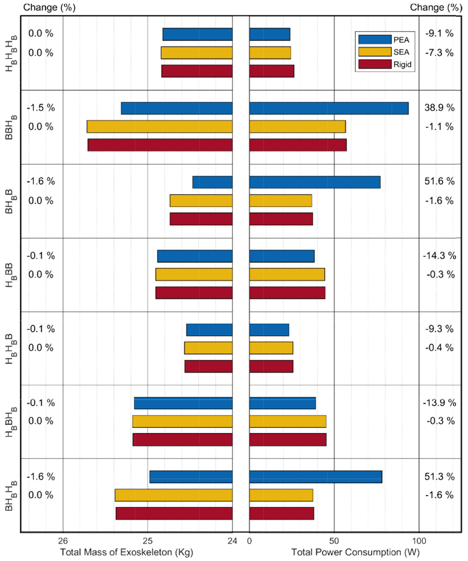
Figure 9 presents the comparison when either the harmonic drive was utilized in combination with a belt and pulley drive system or ball-screws were used. However, the results are presented so that at least two of the lower limb joints have the same transmission system. The minimum value of the total mass for the case of PEA was revealed by using harmonic drives combined with a belt and pulley system at the knee joint and ball screws at the hip and ankle joint. But the total power consumption for this case was reported to be increased. Considering both the total mass and power consumption, the maximum reduction was recorded by using belt and pulley harmonic drive system at the hip and knee joints and ball screws at the ankle joint. This case was also true for SEA.
Based on the results of the optimization algorithm, a virtual prototype was built using Maxon EC45-flat as the electric motor at the hip and knee joints with a harmonic drive CSD-20-160-2A applied with a belt and pulley drive system to achieve a transmission ratio of 1:400 and Allied motion MF60020 with an SDF ball-screws was used at the ankle joint. According to the findings above, these combinations of the actuation systems were considered the optimal ones for a parallel elastic actuator. Therefore, a virtual prototype of an assistive robotic exoskeleton was implemented using the physical components built in SimMechanics and integrating it with the prototype developed in SolidWorks. A speed-controlled DC motor was realized using a PID controller integrated with an H-bridge. Several designs of DC motor were implemented. A virtual model of the exoskeleton developed is illustrated in Fig. 10. The total power consumption and weight of the exoskeleton were 20.1 W and 24.5 kg respectively using the virtual prototype developed using the optimum motor and transmission system combination and the optimum values for spring stiffness and equilibrium angles calculated using the proposed optimization algorithm. To verify the results, the outcomes using the virtual prototype were compared with the mathematical model obtained from Section 3.5. The values were similar with only a marginal difference. A high correlation was observed between the mathematical and virtual experimentation model as indicated by the Pearson R-value squared in Fig. 11 for various transmission system combinations. The weight and power consumption of all components of the exoskeleton were included in the prototype. This was true for both SEA and PEA.
A detailed model of the actuation system at the hip, knee and ankle joints of an assistive exoskeleton.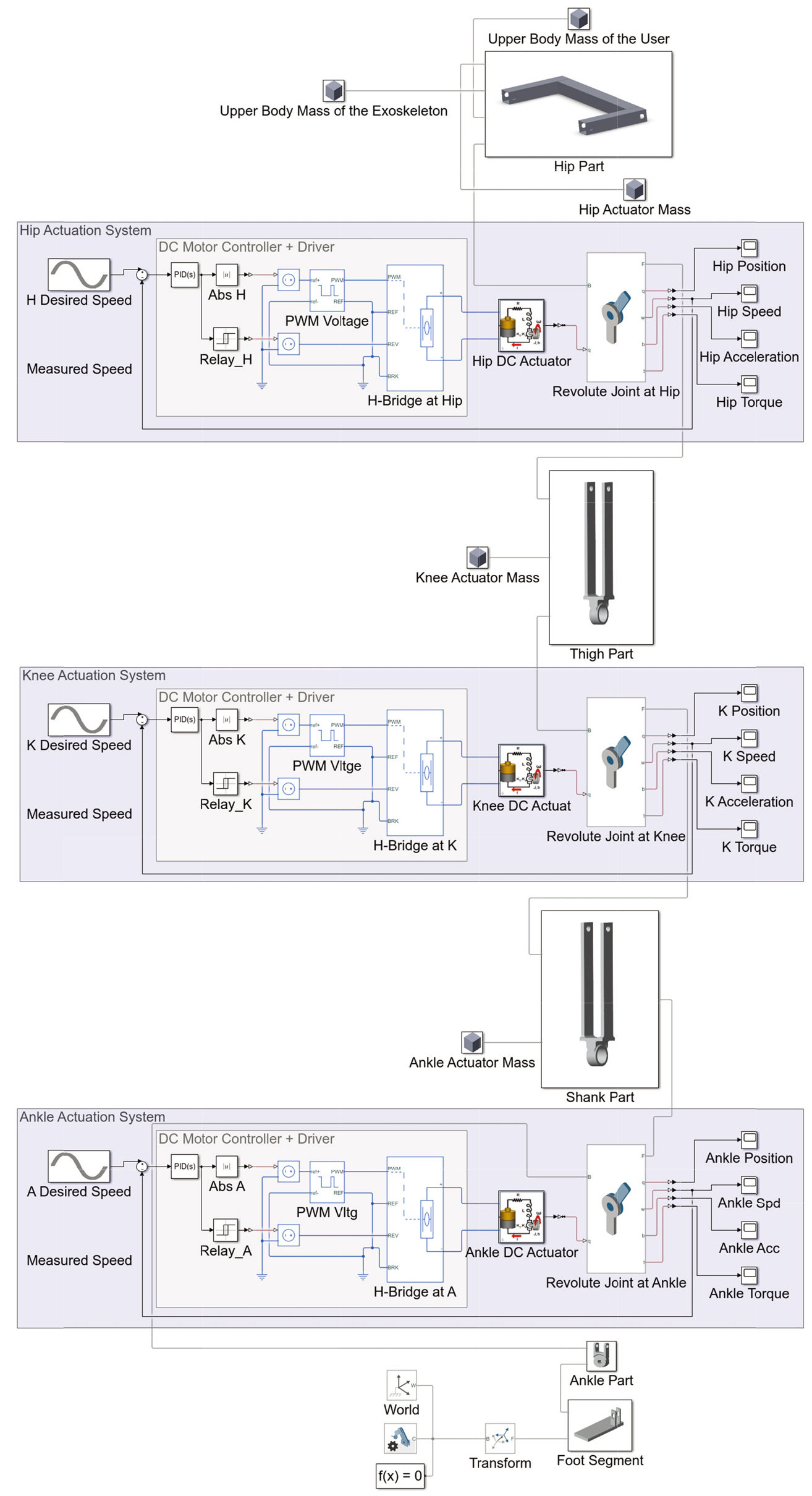
Correlation of total power consumption of the exoskeleton using mathematical and virtual experimentation model for (a) PEA and (b) SEA, 
Experimental prototype of a lower limb exoskeleton.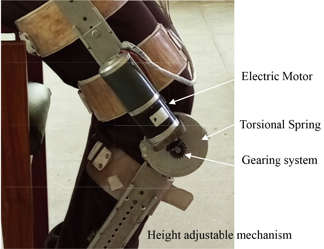
An experimental prototype was implemented as illustrated in Fig. 12. The lower limb structure consists of an electric motor, gearing system and a torsional spring mechanism. The torsional spring will act in parallel to the electric actuation system. The lengths of the thigh and shank were adjustable to accommodate different size of the users. Both sit to stand and level ground operations were performed using the experimental protype and recorded the total power consumption by the exoskeleton. The total power consumption obtained was 30 W. This was measured with the electric current the motor withdrawn and the voltage applied to it.
Discussion
In this paper, an optimal actuation system using series and parallel springs for assistive robotic exoskeletons was developed for maximizing its efficiency. The effect of optimal stiffness of the spring was evaluated based on different minimization criteria. The optimized actuation systems were recorded based on an elastic actuation design framework. This work was able to evaluate different optimization strategies of the spring stiffness and implemented them to determine the optimal actuation system using series and parallel springs. The optimal actuation system was further evaluated using an actuator design solution to minimize the weight and power of the exoskeleton.
When springs are used in robotic exoskeletons, the optimization of the spring stiffness is necessary to achieve the desired results [28]. The stiffness of PEA was settled at a lower value than SEA because PEA has to follow the whole length of change of the actuator during operation. A slight change in the spring stiffness and equilibrium angle of PEA significantly changes the magnitude of the variables of interest. SEA was unable to produce any significant difference in the torque and power requirements of the joint due to a number of reasons. Firstly, in the current exoskeleton model i.e. model without crutches, the walking speed has to be matched with Rex Bionics that is found to be very slow [12]. At a slow speed, SEA did not bring any benefits in the power requirements of the actuation system. Furthermore, since a fixed stiffness actuator was used in this investigation for each operation of sit to stand and level ground walking, it was unable to reduce the requirements for all types of maneuvers. It was suggested that the use of a variable stiffness for each maneuver will bring considerable difference but will increase the cost and complexity of the system. This is also true for the case of PEA. The previous studies showed using variable stiffness for each instant of gait was not power efficient [35, 36]. Therefore, it can be concluded that using a fixed stiffness for each particular maneuver will bring benefits in the power requirements for SEA. As this paper considered only fixed stiffness actuators with the slow walking speed, therefore, it did not prove to be beneficial in the case of SEA. But the torque and power requirement were greatly reduced using PEA. The knee joint was fixed during the stance phase but it was able to freely move during the swing phase to make it more power efficient [37]. The knee locking also affected the speed of the hip joint during the stance phase and hence reduced the power requirements at the hip joint. This is the reason why the power requirement at the hip joint was zero. The double support phase during stance has not been evaluated since the torque and power requirements were not significant during this phase [38].
At the hip joint, it can be said that optimizing spring stiffness by minimizing
The optimization algorithm of the actuation system indicates significant power consumption benefits of the robotic exoskeleton. The power consumption was greatly reduced and hence the size of the required battery is decreased. During the development of the virtual prototype, the optimization of the parameters of the actuation system was found to be a very challenging design task and required a trade-off among different design approaches. It was revealed that the simulation time was much increased when moving towards the full actuation model. In the above task, the controllers used were limited to a simple design otherwise the simulation time would add up with the complexity of the design. The coupling between the controllers was disregarded which alternatively could make the overall system more efficient. The trajectories of the robotic exoskeleton were also predefined and were not subjected to environmental disturbances e.g. a rough terrain or if pushed by another force. The similar values using an experimental setup of an elastic actuation system of an exoskeleton implies the integrity of the mathematical model developed and its verification and hence a lightweight and power-efficient system was resulted for an assistive robotic exoskeleton.
Conclusions
This paper presented an actuator design optimization technique for elastic actuators using series and parallel springs to power the lower limb joints of an assistive robotic exoskeleton so that a matching gait torque-angular profile could be replicated for elderly users. A power-efficient and lightweight system was evaluated using an elastic actuation system as compared to the rigid actuation system. This work has quantified the trade-off between power efficiency and weight of the actuators using elastic elements so that device portability could be better adopted to provide independent assistance to the elderly users. A multifactor spring stiffness optimization approach was developed to optimize the spring based on several design factors. The detailed model of actuators, transmission systems and elastic elements were evaluated, and the springs used in PEA and SEA were optimized to reduce the kinetic requirements of the lower limb joints. SEA was not able to reduce the requirements significantly, however, PEA brought a reduction of up to 90% in the peak torque and peak power requirements of the system. The spring stiffness obtained through the multifactor approach was further used in the elastic actuator design framework to determine the best actuator selection in an elastic actuation system. An experimental prototype was implemented to verify the results. Even though the elastic elements were increasing the complexity of the joint actuators, however, there was a considerable effect that was observed on the weight and power of the system using elastic actuators as compared to the rigid actuation system. A reduction of up to 52% in the power consumption of the resulting exoskeleton was recorded and hence the portability of the exoskeleton could be better adopted to support elderly in performing ADL independently. The optimal design was evaluated using harmonic drives at the hip and knee joints and ball screws at the ankle joint in a parallel configuration of the elastic element. The proposed methodology could also be implemented using the joint level redundancy concept by investigating on the strengths and weaknesses of using two or more actuators at any lower limb joint of the exoskeleton.
Footnotes
Acknowledgments
The corresponding author would like to thank the University of Engineering and Technology Lahore for providing assistance during his PhD studies.
Conflict of interest
The authors declare that they have no conflict of interest.
Funding
The authors report no funding.