
Abstract
X-ray phase computed tomography (CT) is used to observe the inside of light materials. In this paper, we report a new study to develop and test a laboratory assembled X-ray phase CT system that comprises an X-ray Lau interferometer, a rotating Mo anode X-ray tube, and a detector with high spatial resolution. The system has a high spatial resolution lower than 10 μm, which is evaluated by differentiating neighbouring carbon fibres in a polymer composite material. The density resolution is approximately 0.035 g/cm3, which enables to successfully distinguish the high-density polyethylene (HDPE, 0.93 g/cm3) from the ultra-low-density polyethylene (ULDPE, 0.88 g/cm3) in the sample. Moreover, the system can be switched to operate on another mode based on a Talbot–Lau interferometer that provides a wider field of view with a moderate spatial resolution (approximately 100 μm). By analyzing sample images of the biological, this study demonstrates the feasibility and advantages of using hybrid configuration of this X-ray phase CT system.
Introduction
X-ray computed tomography (CT) is widely used for non-destructive, three-dimensional inspection of the interiors of objects. Contrast in X-ray CTs is generated depending upon the X-ray absorption properties of the object. It is known that the contrast is stronger for heavier materials (e.g. metals), whereas lighter materials such as polymers cannot be resolved clearly.
X-ray phase CT, which uses X-ray phase-shifts rather than absorption, has been studied to overcome this problem [1], as the cross section of phase-shift interactions is approximately 1000 times larger than that of absorption interactions. Polymer composite materials, such as carbon fibre reinforced polymers (CFRPs), with which conventional heavy materials are being replaced in many fields, can be potential target materials for X-ray phase CT.
As the coherence of incoming X-rays must be sufficiently high for X-ray phase CT to work, its development was advanced mainly by the appropriate use of synchrotron radiation. Recently, grating-based phase-contrast techniques involving X-ray Talbot interferometers [2] or Talbot–Lau interferometers [3] consisting of transmission gratings have attracted attention. This is because X-ray phase CT can now be implemented using a laboratory-based X-ray source. The interferometers acquire moiré patterns through the gratings and, therefore, the resulting spatial resolution is essentially limited by the period of the gratings. Systems based on an X-ray Talbot interferometer combined with a microfocus X-ray tube [4, 5], were reported to have high magnification obtained by using a projection technique. A spatial resolution corresponding to the focal spot size of the microfocus X-ray tube rather than the grating period can be achieved in this case. However, the scan time is longer because of the limited power of the tube. On the other hand, systems comprising an X-ray Talbot–Lau interferometer and a conventional X-ray tube [6, 7] have been reported to have a shorter scan time, but they only achieve a moderate spatial resolution.
The moiré pattern generated by the Talbot and Talbot–Lau interferometers is de- formed by the absorption and refraction caused by a sample. The fringe-scanning method is applied by acquiring moiré patterns with a step-by-step-movement of one of the greatings [2], to quantify the absorption and refraction pixel by pixel. When these signals are used for CT reconstruction, CT images mapping the absorption coefficient and refractive index are reconstructed.
Furthermore, the visibility reduction in the moiré pattern (or the dark-field signal [8]) provides additional information relating to the ultra-small-angle X-ray scattering caused by the fine structures present in the sample. The scattered X-rays no longer contribute to the moiré pattern formation and, hence, the higher the density of fine structures, the lower the visibility. This signal can also be used for tomographic image reconstruction by introducing a parameter called the linear diffusion coefficient [9].
In this paper, we report a practical X-ray phase CT system that comprises an X-ray Lau interferometer [10], which is one of the grating-based phase-contrast techniques. A prominent advantage of the Lau interferometer is that it is not necessary to place an amplitude grating (called G2) directly in front of the image detector. Therefore, the problem of the spatial resolution limited by the grating period is eliminated. Since highly sophisticated and expensive technology is necessary to fabricate a high-aspect-ratio pattern with a large area on the G2 [11], the G2-less configuration is also advantageous. Moreover, the G2-less configuration is beneficial because all the X-rays passing through the sample are recorded by the image detector, while G2 essentially blocks half of the X-ray flux.
To use the Lau interferometer is that spatial coherence is not required to the X-rays unlike in the case of a Talbot interferometer. This allows for the use of an X-ray tube with a larger focus and a higher flux. Nevertheless, the configuration of the system developed in this study is designed to achieve a spatial resolution lower than 10 μm.
However, since a high spatial resolution implies a limited field of view (FOV), our system is constructed such that it can be switched to a setup based on an X-ray Talbot–Lau interferometer, thus enabling observations with a wider FOV, a moderate spatial resolution, and a higher scanning speed. In this paper, we describe the performance of this new CT system using experimental results.
System configuration
Design of the Lau interferometer
A Lau interferometer consists of an amplitude grating (G0) and a phase grating (G1), as shown in Fig. 1. This configuration is established by removing the amplitude grating (G2) from the inverse Talbot–Lau interferometer geometry discussed by [12].
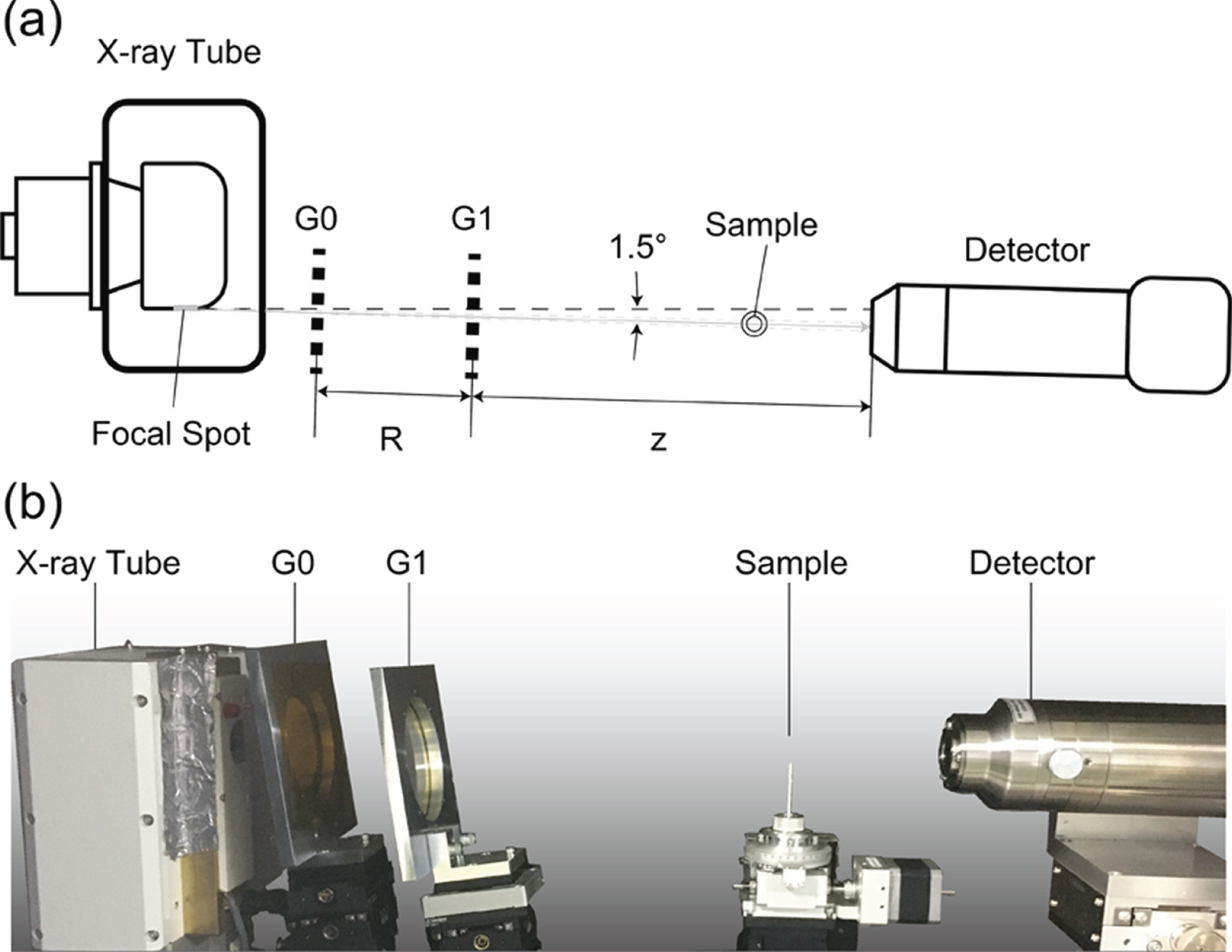
Experimental setup of the X-ray Lau interferometer developed for phase CT: (a) Schematic diagram (top view), (b) photograph (side view).
The G0–G1 distance (R) and the periods of G0 and G1 (d0 and d1, respectively) are selected such that the length of the interferometer is compact and the self-image of G1, which is generated by the fractional Talbot effect [13], can be resolved directly by an image detector without using G2 to produce a moiré pattern. That is,
In designing the Lau interferometer, we applied boundary conditions on the X-ray wavelength (Mo Kα emission line, 17.4 keV) and the total length of the interferometer (<500 mm). As a result, d0 and d1 were set to 3.77 μm and 3.14 μm, yielding values of 83 mm and 412 mm for R and z, respectively.
In this setup, an image detector that can resolve the self-image should be used. We used a CCD-based detector (XSight Micron, Rigaku Innovative Technologies Europe, S.R.O., Czech) having a scintillator and a coupling lens with an effective pixel size and array size of 0.54 μm×0.54 μm and 3326×2504, respectively. Figure 2 shows a self-image captured by this image detector, where the period d2 was evaluated to be 18.8 μm and the fringe visibility was approximately 50%.
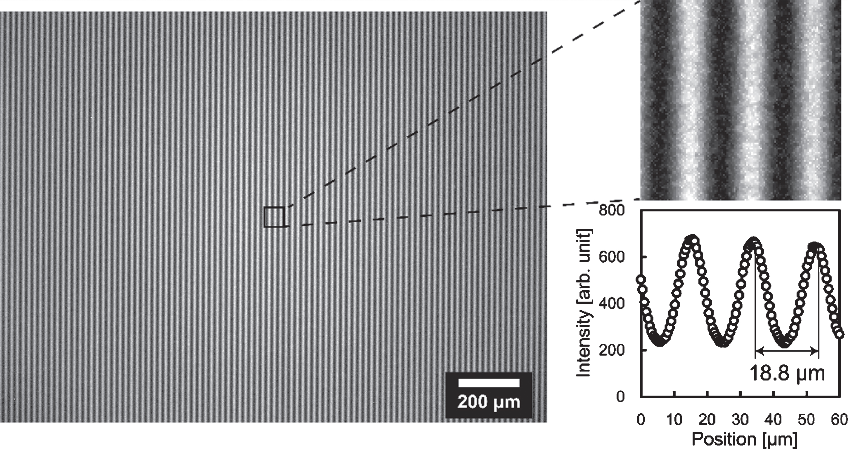
Self-image generated by the Lau interferometer. The period d2 and the visibility of the fringes are 18.8 μm and approximately 50%, respectively.
The gratings used in this study were fabricated by microworks GmbH, Germany. Note that G0 was an amplitude gold grating having a bridge structure for preventing the pattern from collapsing [14]. When the gratings were set perpendicular to the X-ray path, the bridges affected the resulting images. However, we found experimentally that the bridge feature was moderately suppressed when the grating was inclined by 9°. Hence, we employed the alignment shown in Fig. 1(b) in the current work.
The spatial resolution and sensitivity to refraction are affected by the position of the sample when using grating-based phase-contrast techniques [12]. Although placing the sample close to the detector is preferable to ensure a reasonable spatial resolution, according to the contrast mechanism of the Lau interferometer, a finite distance between the sample and the detector (i.e. z′) is essential for creating sensitivity to refraction and scattering in the sample. Therefore, the penumbra due to the finite X-ray focal spot size and z′ should be considered in determining the system configuration. The sensitivity to refraction is proportional to z′ and is inversely proportional to the magnification M, which is given by (R + z)/(R + z–z′). M affects the sensitivity to refraction because the wave front modulated by the sample is stretched at the detector position by the cone-beam illumination, causing a reduction in the wave front slope by M. Figure 3 shows the estimated spatial resolution and sensitivity to refraction as functions of z′ in the Lau interferometer configuration described above under the condition that, the distance between the X-ray focal spot and G0 is 120 mm and the focal spot size is 16.5 μm as mentioned below. Although the sensitivity to refraction reaches a maximum at z′= 300 mm in Fig. 3, in the present study, we report the results obtained with z′= 120 mm, which predicts a spatial resolution of approximately 5 μm. The effective FOV in this case is approximately 1.44 mm×1.09 mm.
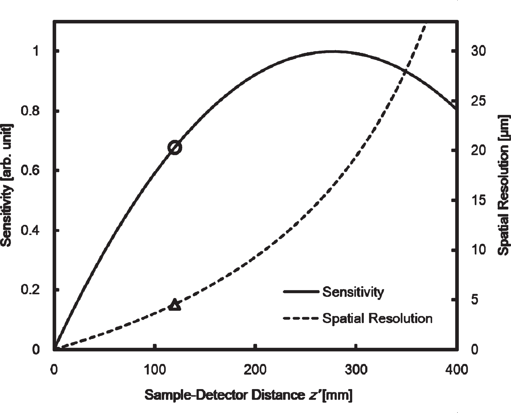
Theoretical spatial resolution and sensitivity to refraction as functions of distance z′ between the sample and the detector. The symbols ˆ and Δ at z′= 120 mm indicate the values selected in this study.
An X-ray tube composed of a Mo rotating anode (modified from RA-Micro7HFMR, Rigaku, Japan) is used in this study. The focal spot size on the target is 630 μm (horizontal)×41 μm (vertical), and an X-ray beam is extracted with a 1.5° take-off angle against the target surface, with an effective source size of 16.5 μm (horizontal)×41 μm (vertical). The X-ray focal spot is located 120 mm away from the centre of G0 in this configuration.
The CT system in this section is characterized by a special function such that the configuration with the Lau interferometer and the configuration with a typical Talbot–Lau interferometer can be switched to each other. The former is used for high-resolution observations while the latter is used for observations with a larger FOV but a compromised spatial resolution. The X-ray tube, G0, and G1 are shared between both the configurations. A schematic diagram of the configuration with a Talbot–Lau interferometer is shown in Fig. 4. The gratings are inclined at an angle for the same reason as mentioned in the case of Fig. 1. In the Talbot–Lau configuration, the self-image of G1 is not resolved by a high-resolution detector; instead, a moiré pattern is recorded by using an amplitude grating G2. In this system, G2 with a period of 18.8 μm is placed 414 mm downstream of G1 to generate moiré patterns. A photon-counting pixel detector (Hypix-3000, Rigaku Corp., Japan), having a pixel size and array size of 100 μm×100 μm and 385×775, respectively, is placed 75 mm behind G2 to capture moiré patterns. An X-ray beam is extracted with a 6° take-off angle against the target surface, and the distance between the focus and G0 is changed to 95 mm from that in the Lau configuration. The sample is placed 130 mm downstream of G1 and the effective FOV is approximately 17.8 mm×35.9 mm, with a moderate spatial resolution of approximately 100 μm. Thus, the entire sample can be scanned by the Talbot–Lau configuration with a larger FOV and a shorter scanning time; however, only a part of the sample can be scanned by the Lau configuration, but with a higher spatial resolution.
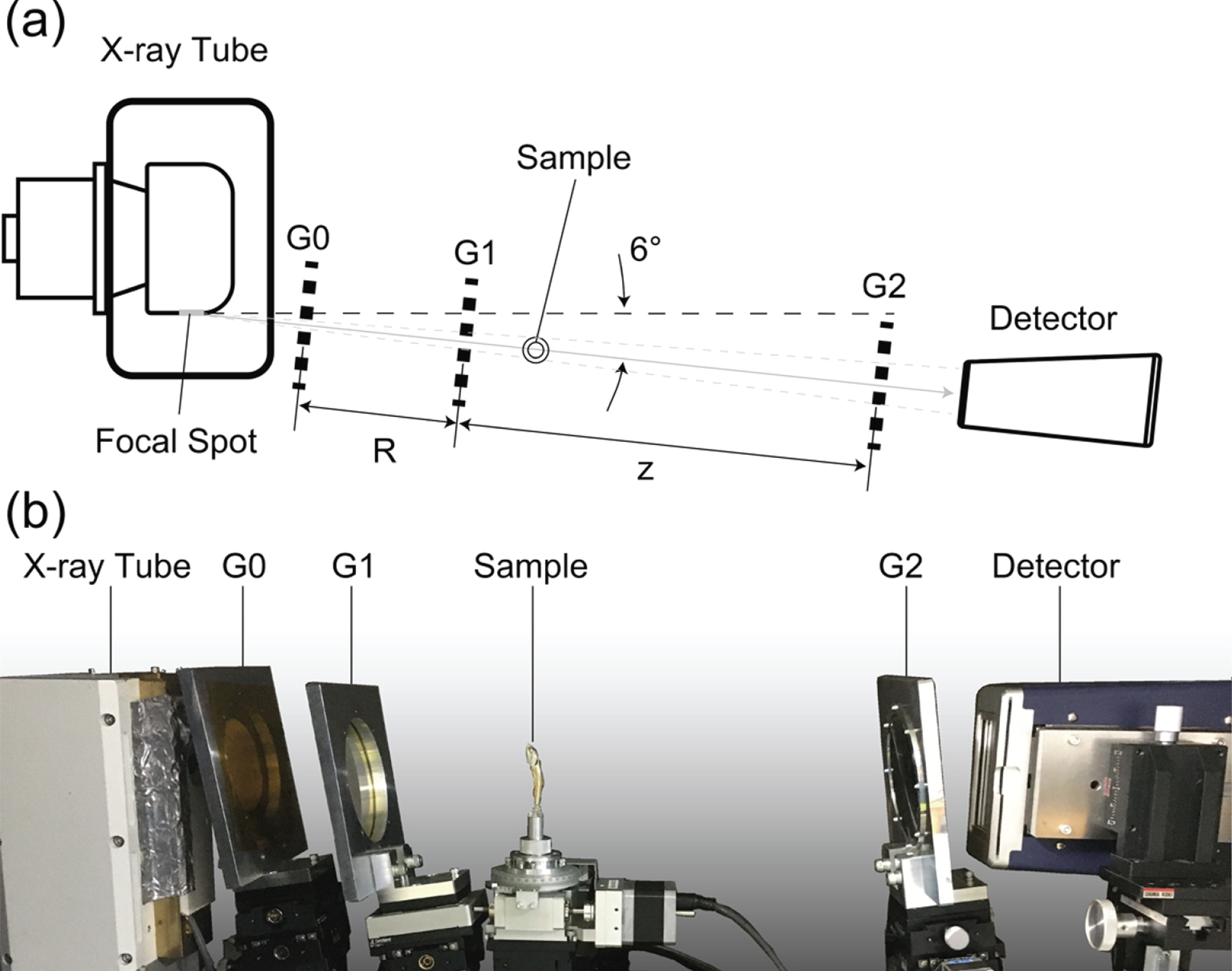
Experimental setup of the X-ray Talbot–Lau interferometer for the phase CT: (a) Schematic diagram (top view), (b) photograph (side view). The configuration with the Lau interferometer is switched to this configuration if observation with a larger FOV (but a compromised spatial resolution) is needed.
To obtain the results presented in this section, a 5-step fringe scanning measurement [2] was performed at 360 angular positions over a 180° sample rotation. For tomographic re-construction, the conventional filtered back-projection method was used with the parallel-beam approximation. The Ram-Lak filter was employed as the kernel for CT reconstruction from absorption and visibility reduction, and the Hilbert filter was used for reconstruction from refraction. The operation parameters of the X-ray tube, except for the take-off angle, were identical in the Lau and Talbot–Lau configurations. The exposure time at each fringe-scanning step was 120 s for the Lau configuration and 5 s for the Talbot–Lau configuration.
Figure 5 shows the images obtained for a polyethylene (PE) pipe with an outer diameter of 5 mm and an inner diameter of 3 mm in the Talbot–Lau configuration. This pipe consists of 2 layers: the inner layer is made of high-density PE (HDPE, 0.93 g/cm3) and the outer layer is made of ultra-low-density PE (ULDPE, 0.88 g/cm3).
Axial CT images obtained with the Talbot–Lau configuration: (a) absorption, (b) phase, and (c) visibility. The sample is a pipe composed of HDPE as the inner layer and ULDPE as the outer layer.
The contrast-to-noise ratio (CNR) between HDPE and ULDPE of the phase CT image (Fig. 5(b)) is 2.18, which is superior to the value 0.81 obtained for the absorption CT image (Fig. 5(a)). Considering that the density difference between HDPE and ULDPE is 0.05 g/cm3, the density resolution is evaluated to be approximately 0.023 g/cm3 for the phase CT and 0.062 g/cm3 for the absorption CT in the Talbot–Lau configuration.
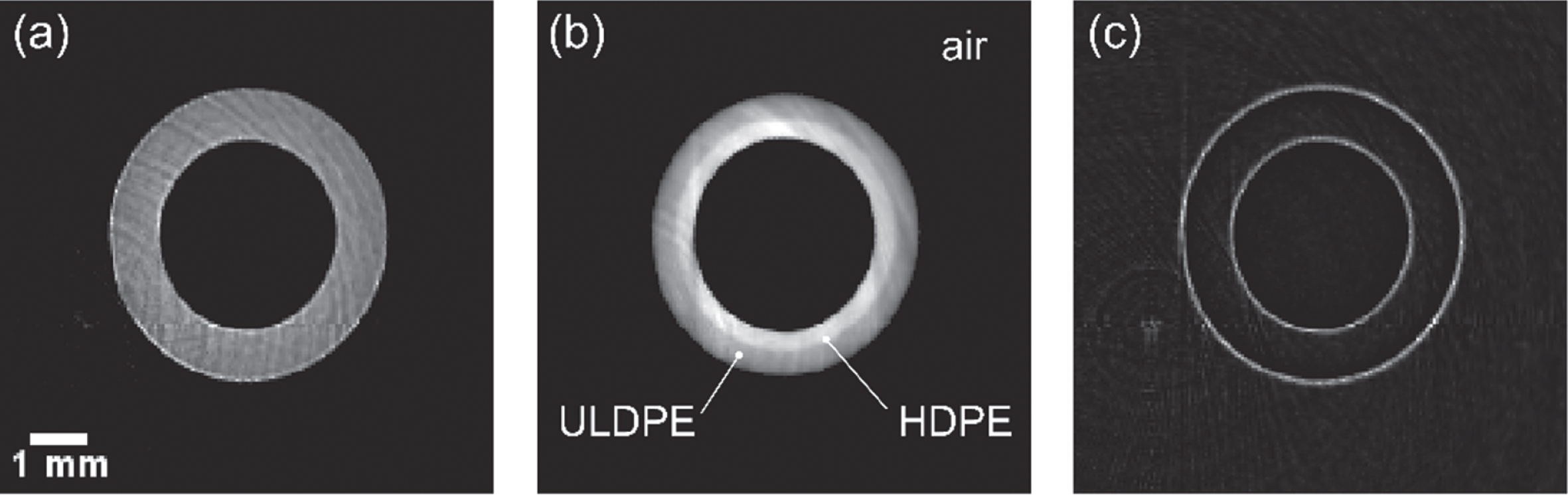
Figure 6 shows the images obtained with the Lau configuration, which provides a higher spatial resolution for a piece of the pipe that was cut out to fit the FOV. The CNR between HDPE and ULDPE in the absorption CT image (Fig. 6(a)) and the phase CT image (Fig. 6(b)) is 3×10⁻³ and 1.49, respectively. The density resolution is evaluated to be approximately 0.035 g/cm3 for the phase CT, but its value is not clear for the absorption CT in the Lau configuration.

Axial CT images obtained with the Lau configuration: (a) absorption, (b) phase, and (c) visibility. The sample is a piece of the pipe used for the measurements shown in Fig. 5.
Figure 7 shows the 3D rendered images obtained for a piece of carbon fibre sheet molding compound (CF-SMC) with the Talbot–Lau configuration, and Fig. 8 shows the results obtained for the tip of the CF-SMC sample with the Lau configuration. Two neighbouring carbon fibres can be resolved in the absorption CT image (Fig. 8(a)) as well as in the phase CT image (Fig. 8(b)). Figure 9 shows the line profiles across the two neighbouring fibres (marked by boxes A and B in Fig. 8) and the corresponding double Gaussian fitting results. From the half-distance between the two peaks in the profiles, the spatial resolutions in the absorption and phase CT images are evaluated to be approximately 4 μm and 8 μm, respectively. Note that the absorption CT image (Fig. 8(a)) undergoes edge enhancement (that is, a type of phase contrast) generated by the X-ray propagation between the sample and the detector [15]. We speculate that the higher spatial resolution in the absorption image is due to this effect.
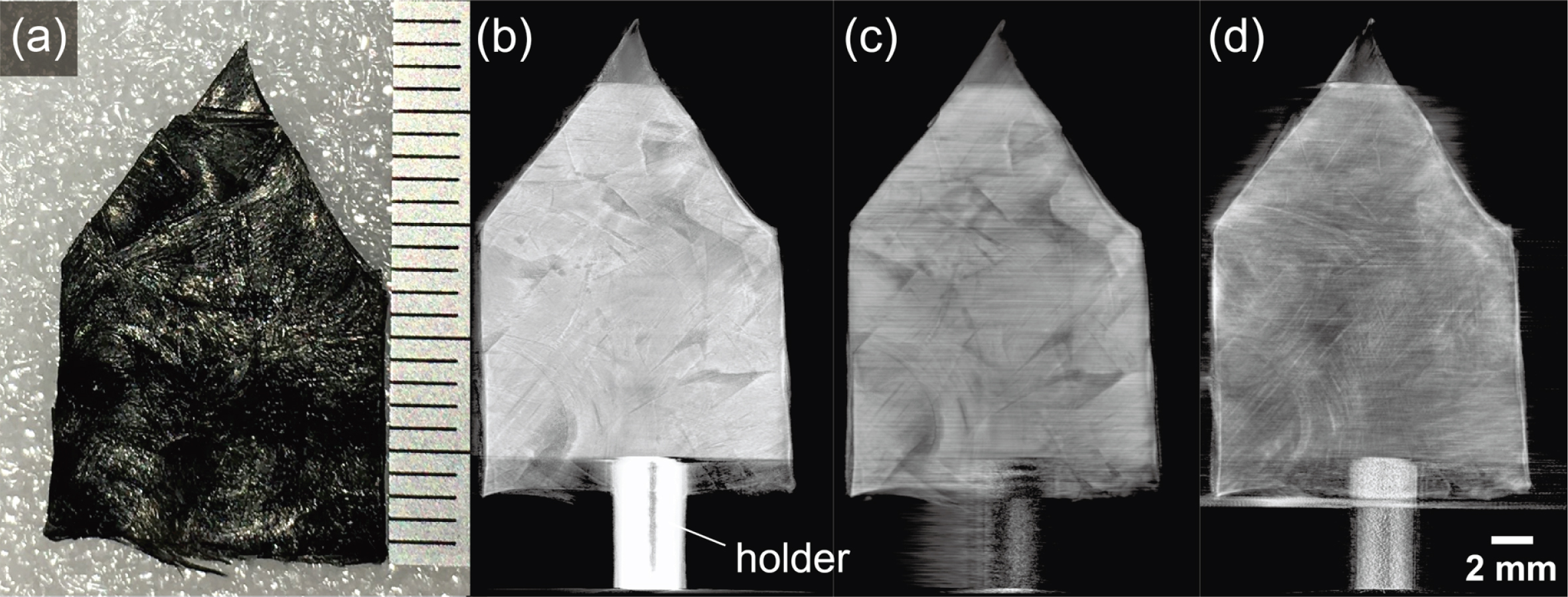
(a) Photograph of a piece of CF-SMC, and coronal view of the 3D rendered images obtained with the Talbot–Lau configuration: (b) absorption, (c) phase, and (d) visibility.

Figure 10 shows the 3D rendered images obtained for a dried fish (infant sardine) with the Talbot–Lau configuration. In the absorption CT image, the contrast produced by the bones is dominant, while in the phase CT image, the contrast due to the muscles and some organs is more pronounced. In the visibility CT image, the contrast produced by the stomach and intestines is more prominent, suggesting that the microstructures in these organs are probably food particles.
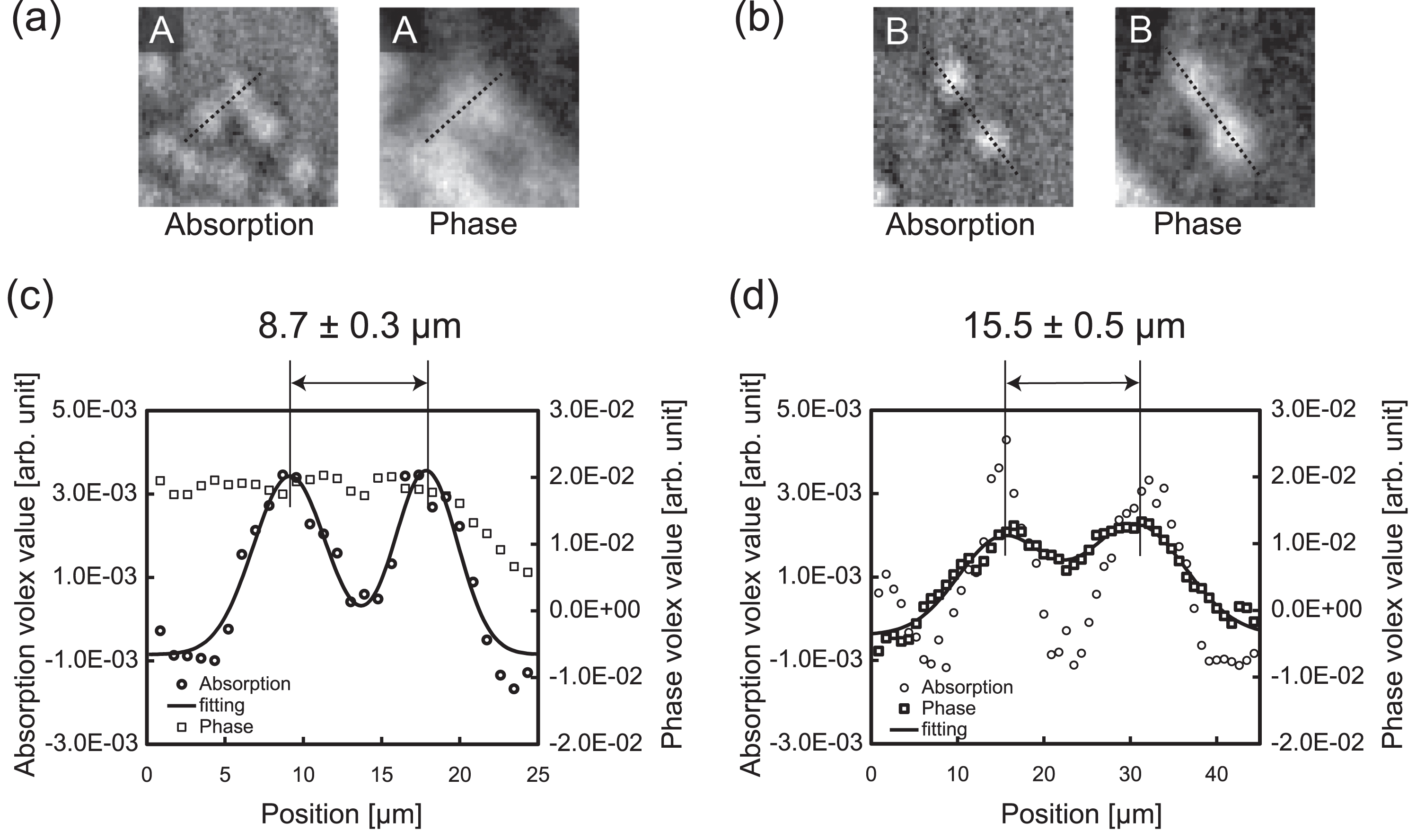
Profiles across two neighbouring single carbon fibres (demarcated by boxes A and B) in the absorption and phase CT images of Fig. 8. Enlarged images inside box A (a) and box B (b). Double Gaussian fitting results for the line profiles showing the spatial resolution for the CT images in absorption (c) and phase (d).
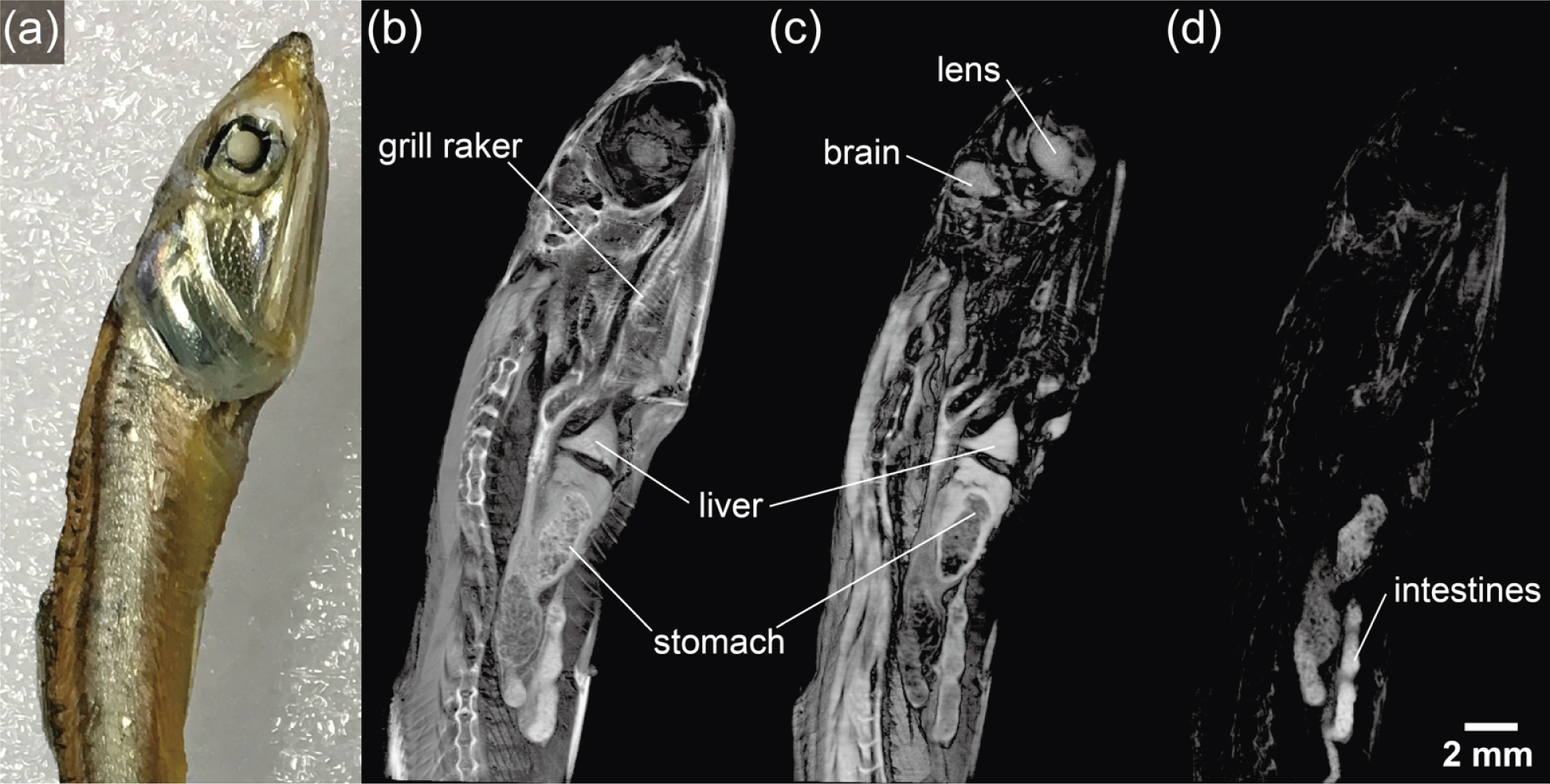
(a) Photograph of a dried fish (infant sardine) used as the sample, and sagittal view of the 3D rendered images obtained with the Talbot–Lau configuration: (b) absorption, (c) phase, and (d) visibility.
Figure 11 shows the results obtained with the Lau configuration, with the sample being the intestine extracted from the dried fish. While the existence of microstructures is suggested in Fig. 10(d), they are resolved more clearly in the phase micro-CT image (Fig. 11(c)), thanks to the higher spatial resolution of the Lau configuration. In the phase micro-CT image, an intestinal wall can be additionally discerned.

(a) Photograph of the intestine extracted from the sample studied in Fig. 10, and axial CT images obtained with the Lau configuration: (b) absorption, (c) phase, and (d) visibility.
The design of the hybrid CT system described in this paper was selected by considering the specifications of the X-ray source, gratings, and image detector available to us. As shown in Fig 3, the design was not adopted with the aim of achieving the best possible sensitivity because the spatial resolution would then be considerably compromised. To improve the sensitivity without changing the spatial resolution and the entire size of the system, an X-ray source with a smaller focal spot size and/or an X-ray image detector with a smaller pixel size need to be used. However, we need to accept a much longer CT scan time. If a high-flux microfocus X-ray source, such as a microfocus rotating anode X-ray tube, is developed in the future, the performance of the system presented in this work will be upgraded considerably without compromising the achieved spatial resolution.
In this work, two modes of the X-ray phase CT system were demonstrated by using the same samples. One mode consists of the Lau interferometer and the other the Talbot–Lau interferometer. However, to use the Lau configuration, a thin part of the sample or a small piece excised from the sample needs to be measured. This is because the size of the sample should be smaller than the FOV according to the scheme of the conventional CT. One of the possible applications of the hybrid CT system presented here could be as follows: once the Talbot–Lau configuration identifies the region-of-interest, it can be directly scanned by the Lau configuration without having to dissect the sample. For this purpose, we propose the introduction of zoom CT or local CT techniques [16, 17] in the near future.
When switching between the setups of the Lau and Talbot–Lau interferometers, the take-off angle of the X-rays from the anode is changed because the preferable take-off angle (or spot size) is different between the two setups. Therefore, the positions of all the interferometer components should be changed accordingly. Since the X-ray tube used in this study has a beam ports on each side, the two interferometers can also be installed independently of each other. In this way, the use of the CT system in both the configurations becomes more flexible. Furthermore, provided that the take-off angle is changeable by simply rotating the X-ray tube, a common beam path can be shared by the Lau and Talbot–Lau interferometers. Thus, seamless scanning can be performed by only moving the gratings and the samples along the beam path.
Conclusion
In this work, a laboratory X-ray phase CT system with a Lau interferometer consisting of only G0 and G1 (without G2) was developed with a spatial resolution lower than 10 μm. A density resolution of approximately 0.035 g/cm3 was demonstrated by differenti-ating the HDPE from the ULDPE in the sample. The system also contains another setup comprising a Talbot–Lau interferometer for phase CT with a moderate spatial resolution and a wider FOV. The CT system can be switched to operate between the two setups. We expect that this hybrid CT system will be highly effective for studying various polymer or polymer composite materials and biological specimens.
Footnotes
Acknowledgments
This research was supported by the SENTAN project of the Japan Science and Technology Agency (JST).