
Abstract
OBJECTIVE:
To reduce secondary artifactes generated by the current interpolation-based metal artifact reduction (MAR) methods, this study proposes and tests a new Poisson fusion sinogram based metal artifact reduction (FS-MAR) method.
METHODS:
The proposed FS-MAR method consists of (1) generating the prior image, (2) forward projecting this prior image and applying the Poisson blending technique to seamlessly replace the metal-affected sinogram of the original projection in the metal projection region (MPR) by the prior image projection to get the corrected metal-free sinogram, and (3) performing the filtered back projection (FBP) on the corrected sinogram and filling the metal image back to the metal-free corrected image to get the final artifact reduced image. Simulated images are calculated by taking clinical metal-free CT images as phantoms and inserting metals during the simulated projection process to get the corresponding metal-affected images by the FBP. After the simulated images are processed by the proposed MAR method, two metrics structural similarity index (SSIM) and peak signal-to-noise ratio (PSNR) are used to evaluate image quality. Finally, visual evaluation is also performed using several real clinical metal-affected images obtained from the Revision Radiology group.
RESULTS:
In two testing samples, using FS-MAR method yields the highest SSIM and PSNR of 0.8912 and 30.6693, respectively. Visual evaluation results on both simulated and clinical images also show that using FS-MAR method generates less image artifacts than using the interpolation-based algorithm.
CONCLUSIONS:
This study demonstrated that with the same prior image, applying the proposed Poisson FS-MAR method can achieve the higher image quality than using the interpolation-based algorithm.
Introduction
X-ray computed tomography (CT) is widely used in the clinical diagnosis. In general, high-resolution images and reliable anatomical information can be achieved through CT scanning. However, if metallic objects (such as dental fillings, joint prosthesis, implants, etc.) exist in the scanning field, major artifacts caused by severe beam hardening, photon starvation, scatter and so on will appear in the final image, which may lead to misdiagnosis. Many metal artifact reduction (MAR) methods have been proposed to solve this problem and the main challenges continue to be cases with large, dense metal implants, as well as cases with multiple metal objects in the field of view [2]. Among these methods, the image based methods can be classified into two categories: integrating MAR into iterative reconstruction methods [3–5] and image based postprocessing algorithms [6–12]. The iterative algorithms can achieve acceptable results, but its high computation time limited its application so that the image based postprocessing methods are still commonly used in application systems.
If the projection line passes through the metal area, due to severe beam hardening and photon starvation, the corresponding projection is unreliable. Some researchers [13, 14] proposed to replace the metal-affected projections with surrogates. The processing procedure is as follows: reconstruct image from the projections, determine the metal area in the image domain, project the metal boundary to get the metal track in the projection domain, replace the metal-affected projections with the linear interpolation of its neighboring unaffected projections for each projection view, reconstruct the metal-free image from the repaired projections. This procedure is called the linear interpolation-based MAR (LI-MAR) and becomes a fundamental framework of the image based postprocessing MAR methods. LI-MAR usually losses the edge information and introduces new artifacts and distorted structures near large metals [15]. By employing a priori information, the forward projection of a prior image is usually a more accurate surrogate of the missing data [16]. The quality of the prior image is very important to the prior image based MAR methods, much effect has been done to build more accurate prior images [10, 18]. Wang et al. [10] proposed a fusion based method to generate the prior image, which combines the pre-corrected image and the originally reconstructed image with metal parts removed to construct the prior image. Zhang et al.[12] proposed to generate better prior images by CNN networks. The prior image method can also be transferred to the metal artifact reduction in cone beam CT (CBCT). Park et al. [7] applied the NMAR idea on the dental CBCT and demonstrated its efficiency.
After the prior images are achieved, the most common procedure is to replace the metal affected sinogram by direct or difference linear interpolation in the metal projection region (MPR), which will lead to the data discontinuous around the border of the MPR. Patrick et al. [1] proposed a novel tool based on solving Poisson equations for the seamless editing of image regions. We proposed to apply this tool to seamlessly fusion the prior sinogram to the metal affected sinogram in the metal projection region, which will achieve more continuous sinogram data around the MPR border and expect to have less artifacts caused by the processing progress.
Methods
The proposed idea
The idea of the image based postprocessing methods is to replace the metal-affected projections by the estimated information. The LI-MAR method replaces the metal-affected projections by the linear interpolation of its neighboring unaffected projections, which will lead to the losses of the edge information and introduce new artifacts.
If the corresponding metal-free image (the ground truth) is achieved, the missing data can be filled by the projection of the metal-free image. But in the practical case, we cannot remove the metal and take a scan again to build the ground truth, so the prior image is designed as a predicted metal-free image. The accuracy of the prior image becomes a critical issue, that the more accurate the prior image is, the better quality the result image will be. One commonly used prior image generation method [8, 19] is to segment the pre-corrected images (by LI-MAR) into different tissues such as air, soft tissue and bone, which is called the TP-MAR method because the prior images are generated from several corresponding thresholds. But if the content of the uncorrected image is very complicated, limited categories cannot describe the prior image very well. Wang et al. [10] proposed a fusion based prior image metal artifact reduction method (FP-MAR), which is easy to implement and contains more information in the surrogate data.
After the prior image generated, the following process to correct the projection data by the prior image is usually the difference sinogram interpolation-based method [20]. First, perform forward projection on the prior image and get the prior sinogram; second, let the original sinogram minus the prior sinogram to get the difference sinogram; third, correct the difference sinogram by replacing the data in the metal projection region (MPR) by the linear interpolation of its neighboring pixels; finally, add the corrected difference sinogram to the prior projection to get the corrected sinogram. Comparing to the LI-MAR method, the difference sinogram interpolation method does interpolation on the difference sinogram instead of the original projection sinogram, which can partly overcome the information loss problem. This method is very sensitive to the segmentation result of MPR so that some studies improved the algorithm by increasing the accuracy of the MPR segmentation [21, 22].
Inspired by the fusion idea in the prior image generation procedure, we proposed to design a fusion scheme in the sinogram correction step to replace the difference interpolation. The situation is that the metal-affected projection is incorrect, and the direct linear interpolation-based surrogate calculation method will lead to data loss, then the prior image is proposed to provide the surrogate data in the MPR. But if the metal-affected projection is replaced by the prior projection directly, because of the data discontinuity, new artifacts may appear in the constructed metal-free image. This problem can be solved by the Poisson image editing technique proposed by Patrick et al. [1], which can seamlessly impaint the prior projection to the original projection in the MPR.
Based on the above presentation, a fusion sinogram based method (FS-MAR) is proposed in this paper, as shown in Fig. 1. The main idea is to apply the Poisson blending technique to replace the metal affected sinogram by the prior image’s projection. The prior image generation module can be filled by any existing method. If the segmented prior image is taken, the whole framework is called TPFS-MAR. If the prior image is generated by fusion based method, the corresponding algorithm is called FPFS-MAR.
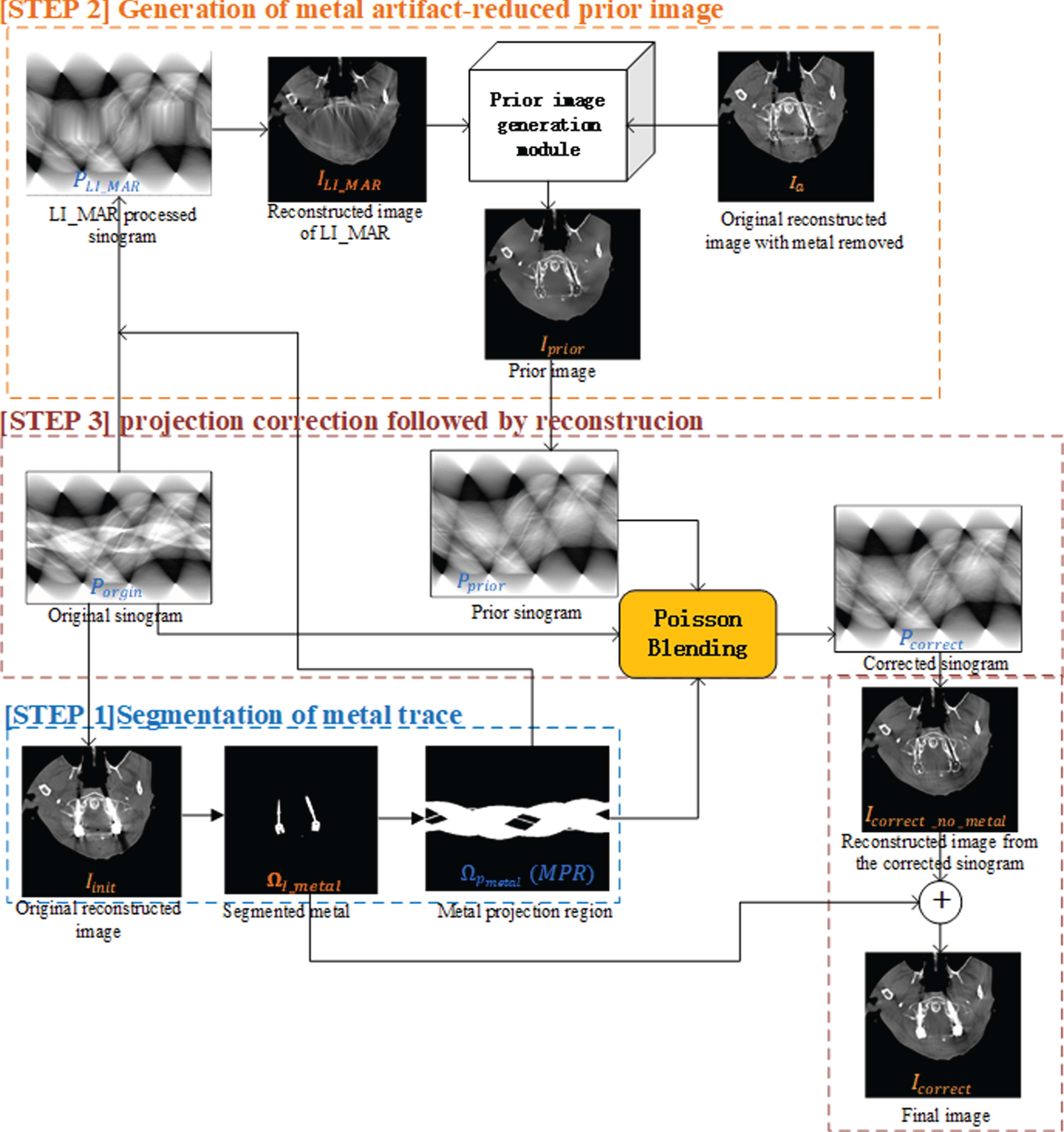
The framework of the fusion based MAR process that consists of three stages: (1) segmentation of the metal trace (the blue dotted box), (2) generation of metal artifact-reduced prior image (the orange dotted box), and (3) Poisson fusion based projection correction followed by reconstruction to achieve the metal-free reconstructed image (the brown dotted box).
Patrick Pérez et al. [1] introduced a novel tool to seamlessly clone an image part into a destination image region, which perfectly satisfies our objective. When listed all the projection lines in sequence, the formed sinogram can be considered as a projection image. If the original sinogram is treated as the background image, the prior projection sinogram as the foreground image and the MPR as the fusion domain, this tool can be used to fusion the prior projection sinogram to the original projection sinogram in the MPR (denoted by Ωp_metal).
Denote the original projection sinogram as P
orgin
(background image), the prior image as I
prior
and the projection sinogram of I
prior
as P
prior
(foreground image). When fuse a foreground image to a background image within a certain region, we expect to get a smooth destination image with a consistent boundary, which can be described by two mathematical conditions: 1, minimum the gradient field difference between the destination image and the foreground image (smooth); 2, the destination image pixels on the fusion region border are equal to the background image (boundary consistence). These two conditions can be described by the following equation:
Where P
correct
denotes the destination sinogram, ∇. is the gradient field operator
So, the solution of Eq. (1) can be described as the following Poisson equation:
Eq. (6) gives an applicable formula to calculate the destination image in the projection domain.
The fusion process in the projection domain of one clinical case is illustrated in Fig. 2. The original image is shown in Fig. 4 (Case 1) in Section 3. In this section we only take the fusion in the projection domain for illustration. The linear interpolation method is shown for comparison. Figure 2(a) is the original projection sinogram in which the metal-affected trace can be obviously observed. Figure 2(b) is the corresponding metal projection region (MPR). In this region, the projection data is untrusted and need to be replaced. LI-MAR calculates the surrogate data directly by linear interpolation and the result is shown in Fig. 2(d). We can obviously observe the linear trace in the corrected projection sinogram, which is not in accordance with the truth. Our fusion based result is illustrated in Fig. 2(c). From the highlighted portions Fig. 2(g) and (h), we can see that compare to the linear interpolation-based approach, the proposed fusion based method can generate a more continuous result sinogram.
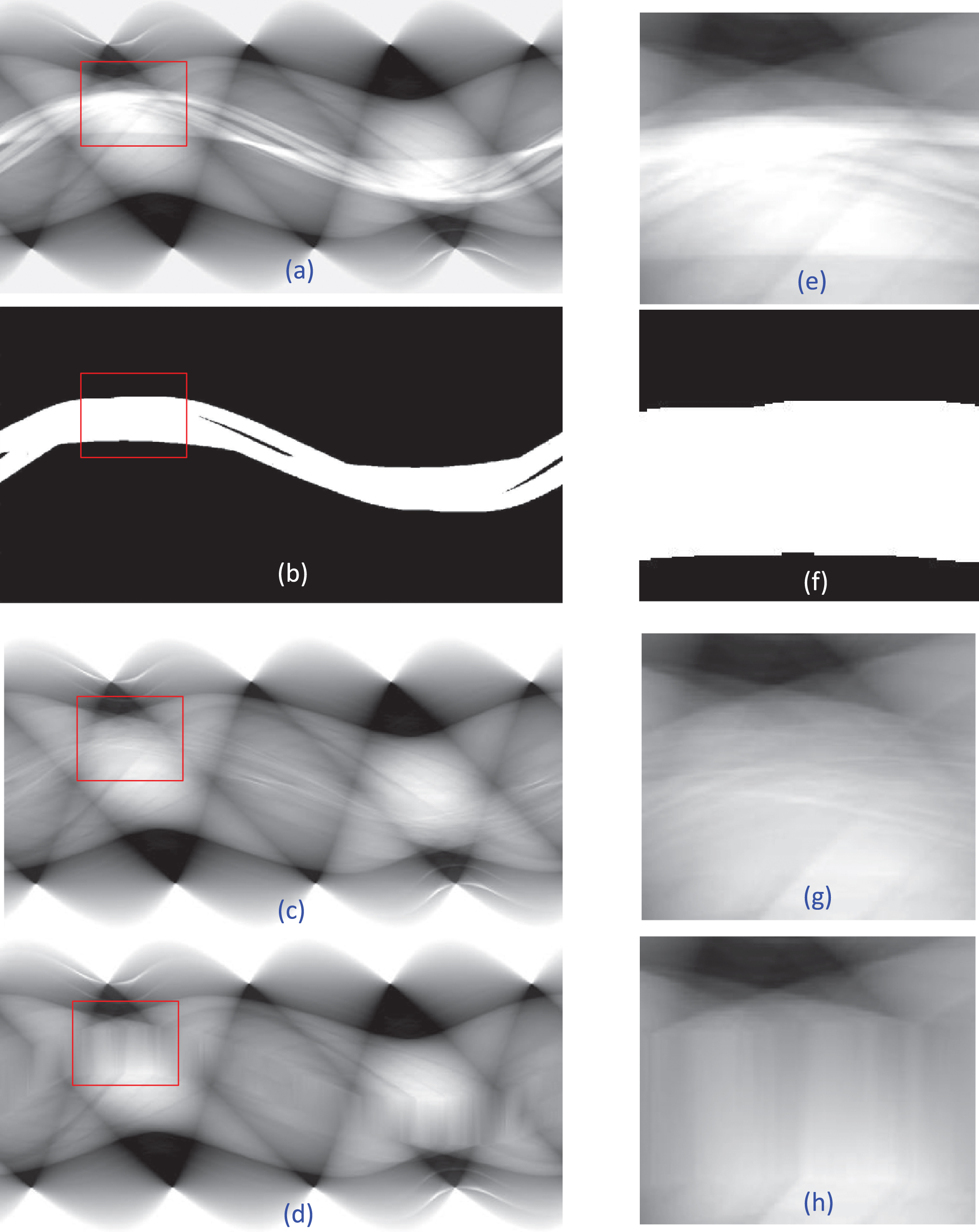
The Poisson fusion in the projection domain: (a) the original projection sinogram of clinical case 1, (b) the metal trace (MPR), (c) the corrected projection generated by Poisson blending, and (d) the corrected projection generated by linear interpolation (LI-MAR). (e), (f), (g) and (h) are the highlighted red portions of (a), (b), (c) and (d) respectively.
From the above description, as illustrated in Fig. 1, the proposed fusion sinogram based method can be summarized as following. The method first performs the filtered backward projection (FBP) reconstruction on the original projection sinogram P
orgin
to get the original reconstructed image, denoted by I
init
. Given a threshold D
metal
, the metal image I
metal
can be segmented out. The metal region in the image domain is denoted by Ω
I
-
metal
. Then remove the metal from the original reconstructed image to get the original metal free image I
a
= I
init
- I
metal
. The metal region in the projection domain Ωp_metal is determined by the forward projection. Apply any prior image generation method to get a prior image I
prior
. With the forward projection, the prior projection sinogram P
prior
is calculated from I
prior
. According to the projection domain fusion method described in Section 2.2, the metal-affected data in the original projection sinogram P
orgin
is seamlessly replaced by the prior projection sinogram P
prior
in the metal projection domain Ωp_metal. The destination sinogram P
correct
is calculated according to the Eq. (6). The method finally performs FBP reconstruction on P
correct
Then, the corrected metal-free image Icorrect_no_metal can be obtained. Then fill back the segmented metal image I
prior
I
metal
in the first step to get the final corrected metal artifact removal image I
correct
= Icorrect_no_metal + I
metal
.
Experiments and discussion
Experiment images
Simulation data were generated by the model introduced in Ref. [12] to evaluate the proposed FS-MAR method. Instead of using phantoms, the authors in Ref. [12] proposed to simulate metal artifacts based on clinical CT images, which is more like to the real cases. The main process of the simulation is as following: first, convert the CT values to linear attenuation coefficients and use some soft segmentation method to separate the result image to bone components and water-equivalent tissue components; second, simulate the polychromatic projection to get the projection data; finally, apply FBP on the projection data, we can get the simulated metal-free image which is considered as ground truth during the following algorithm evaluation. Then some typical metal shapes are segmented from clinical metal-affected CT images and stored. If one or more binary metal shapes with assigned materials are inserted into the proper position during the above simulation, the simulated metal-affected image with metal artifacts can be achieved. Two simulated image groups are listed in Fig. 3.

The simulated images obtained by using normal clinical CT images as phantom. From left to right: (a): the original CT images; (b): the simulated metal-free images; (c) the simulated metal-inserted images (uncorrected images).
During the simulation, an equi-angular fan-beam geometry is assumed. The main simulation parameters were the same as Ref. [12], which are listed as follows: 120 kVp X-ray source, 2*10e7 photons, source to origin distance (SOD) 59.5 cm, 984 projection views and 1025 detector bins in a row. The metal-free and metal-inserted images are reconstructed by FBP from the simulated sinograms and each image consists of 512*512 pixels. The inserted metal material is Ti.
The clinical uncorrected images, with DICOM format, were obtained from the REVISION RADIOLOGY group (http://www.revisionrads.com/CT_metal_DICOM.zip) [5]. To be more precise, the metal artifacts in the three clinical images in Fig. 4, are caused by pedicle screws (Case 1), sternum fixation screws (Case 2) and dental fillings (Case 3) respectively. For each case, the original sinogram was simulated by forward projecting the tested clinical image. The resolution of the CT image is 512×512 pixels and the simulated sinogram is of 605×3600 pixels (605 detector cells, 3600 views). All the CT images were processed by a PC workstation (Intel Core™ i5-7500 CPU @3.4GHz 3.4GHz) under MATLAB R2015b (The MathWorks Inc., Natick, MA). The 2D fan-beam transform and the inverse fan-beam transform were used for the forward projection and filtered back projection, respectively.
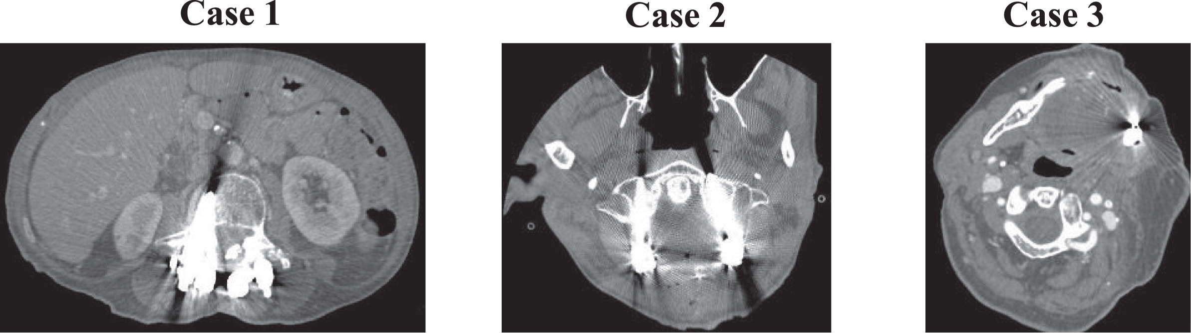
Clinical images. Case 1: pedicle screws (C = 100 HU/W = 1000 HU), case 2: sternum fixation screws (C = 50 HU/W = 900 HU) and case 3: dental fillings (C = 50 HU/W = 900 HU).
The sinogram inpainting methods
With a unique prior image (fusion prior), three sinogram inpainting methods are taken to make the comparison to illustrate the effect of the proposed Poisson fusion method, as shown in Fig. 5. We can clearly observe the metal trace in the original sinogram (Fig. 5(a)). If the sinogram is reconstructed by the FBP reconstruction method directly, the metal artifacts are obvious in the result image (Fig. 5(b)). So, the metal affected sinogram need to be replaced by the estimated information which can be the linear interpolation of the neighbor values of MPR (LI-MAR) or the projection of the estimated prior image. To illustrate what happened after the sinogram inpainting, we select one projection line (the 80th degree) and plot it in a diagram (Fig. 5(c)), where the horizontal axis is the position and the vertical axis is the projection value. If the metal-affected sinogram is replaced by the prior image projection directly, we can obviously observe the numerical jump at the MPR border (indicated by red arrows, the green plot line), which will lead to the algorithm generated artifacts in the reconstructed image (Fig. 5(d)). In comparison, the proposed Poisson fusion method achieve a more continuous projection line (blue) and less artifacts in the reconstructed image (Fig. 5(e)).

The comparison of different sinogram inpainting methods: (a) the original sinogram; (b) the uncorrected image reconstructed from the original sinogram; (c) the plot of the 80th projection line resulted from different sinogram inpainting methods: the ground truth (red), replace the metal affected projection by the prior image projection directly (green), LI-MAR (grey) and the proposed Poisson fusion method (blue); (d) and (f) are the images reconstructed from the directly replaced sinogram and the Poisson fusion sinogram respectively.
When incorporate the proposed sinogram inpainting method into the MAR framework (Fig. 1), the evaluation can be done on the corrected images. With the ground truth, two measure metrics: structural similarity index [23] (SSIM) and peak signal-to-noise ratio (PSNR) were selected to quantitively evaluate the results of different MAR methods. SSIM is the metric to evaluate the similarity of two images, here it is used to evaluate the similarity between the corrected image and the ground truth. PSNR is used to evaluate the image quality of the corrected image. The quantitative results are listed in Table 1 and the best result of each case is marked in bold. The corresponding images are listed in Fig. 6.
Quantitative evaluation of different metal reduction methods executed on the simulated cases
Quantitative evaluation of different metal reduction methods executed on the simulated cases

The experimental results of the simulated cases: the simulated uncorrected image, the ground truth, the metal reduction result images of LI-MAR, TP-MAR, TPFS-MAR, FP-MAR and FPFS-MAR respectively.
Different prior image generation methods: the multi-threshold segmentation method (TP-MAR) and the fusion prior based method (FP-MAR) [10] were applied to generate the prior image. When generating the fusion prior images, the fusion parameter d is assigned to 0.3 and 0.45 for the two test images respectively. With the proposed Poisson fusion sinogram inpainting method, the two corresponding MAR methods are denoted as TPFS-MAR and FPFS-MAR respectively. The sinogram inpainting method of comparison is the commonly used difference interpolation method.
From Table 1 and Fig. 6, we can see that the metal reduction results are quite affected by the quality of the prior image. TP-MAR generates the prior image by segmenting the pre-corrected image into three categories: air, soft tissue and bone, which may lose information around the metal while the fusion based prior (FP-MAR) can preserve more information. Due to the information loss, the tissue may deform sometimes, which is not acceptable in medical cases (indicated by red arrow in Fig. 6). With the same prior image, the visual effects are close to each other (TP-MAR and TPFS-MAR, FP-MAR and FPFS-MAR). Due to the limited quality of the prior images, all the processed results are not so satisfied, but when the prior image is fixed, from the quantitative evaluation results it can be seen that the proposed fusion sinogram method performs better than the difference interpolation method.
The experimental results of different metal reduction methods are illustrated in Fig. 7, which illustrates the correction results for Cases 1, 2 and 3. Severe streak artifacts tangent to the metallic objects in uncorrected images are displayed. Many new streak-like artifacts remain when applying the LI-MAR correction. Some important tissue structures in Case 1 and 2 (indicated by red arrows) are lost in the processed results of TP-MAR and TPFS-MAR. In comparison, the results of FP-MAR and FPFS-MAR preserve more tissue structure close to the metal area. When compared to LI-MAR, TP-MAR and TPFS-MAR work better in both preventing the introduction of new artifacts and preserving tissue structures near the metals. But there are still some dark or bright artifacts remaining around the metal objects in the TP-MAR and TPFS-MAR processed images due to the limited tissue categories and structures in building the prior image. In case 3, we can observe some produced artifacts in the results of LI-MAR, TP-MAR, and TPFS-MAR. The produced artifacts become lighter in the results of FP-MAR and FPFS-MAR (see the ROI of Case 3).
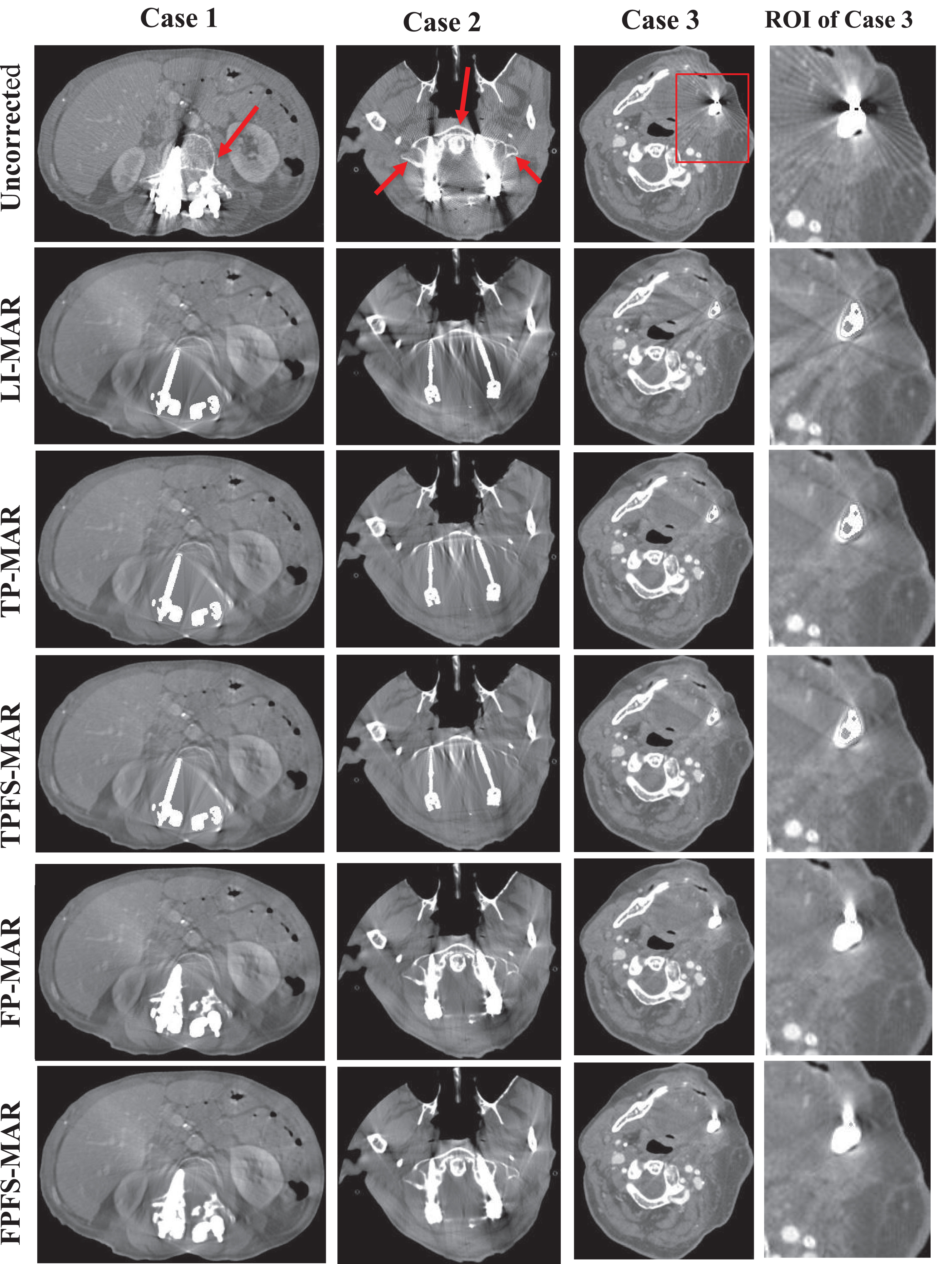
Three sets of correction results corresponding to Cases 1–3. Each set contains the uncorrected image and the result images of LI-MAR, TP-MAR, TPFS-MAR, FP-MAR (d = 0.45), FPFS-MAR (d = 0.45) methods. The red arrows indicate some important tissues to be preserved.
Among the image based postprocessing metal artifacts reduction methods, two key aspects which can affect the final processed results are the prior image estimation and the sinogram correction method. When the threshold based prior image is applied, the proposed Poisson fusion based sinogram replacement method (TPFS-MAR) get higher SSIM and PSNR value than the difference interpolation method (TP-MAR). In the same sense, when the fusion prior image is applied, the proposed sinogram impaint method (FPFS-MAR) get higher SSIM and PSNR value than the difference interpolation method (FP-MAR). We can get the result that when the prior image is fixed, the proposed Poisson fusion based sinogram correction method performs better than the difference interpolation method. But when comparing the results of TPFS-MAR and FPFS-MAR, we can see that the results are also affected by the quality of the prior image. If enough qualified data can be simulated or scanned, some new techniques, such as Convolutional Neural Network (CNN) based technique [12] can be used to estimate better prior image. When deal with low-dose CT, the artifacts can also be caused by data missing [24], the techniques in processing low-dose CT should also be involved.
Conclusion
In this paper, a new Poisson fusion based sinogram based metal artifact reduction or correction method is presented to get the corrected sinogram after the prior image is generated. First, the prior image is built by some existing methods; then the data in the metal projection region is replaced by the projection of the prior image through the Poisson fusion technique to get the corrected sinogram; finally, the corrected metal-free image is reconstructed by applying a back projection algorithm on the corrected sinogram. From the experimental results, we observe that the Poisson fusion technique can improve the quality of the corrected sinogram compared to the directly replace or interpolation-based methods, but the experimental results are also quite affected by the quality of the prior image. Thus, the future research efforts on the postprocessing MAR methods can be focused on the improvement of the estimation accuracy of the prior image.
Footnotes
Acknowledgments
This work was supported in part by Fundamental Research Funds for the Central Universities under Grant 2242020K40053, in part by Natural Science Foundation of Jiangsu Province under Grant BK20150647. The authors are very grateful for the CT images provided by the REVISION RADIOLOGY group of Department of Radiology, Stanford University Medical Center. The authors also greatly thank Dr. Yanbo Zhang from the Department of Electrical and Computer Engineering, University of Massachusetts at Lowell for helping us generate the simulated data.