
Abstract
BACKGROUND:
In fan beam X-ray imaging applications, several X-ray images sometimes need to be stitched together into a panoramic image because of the size limitations of the detector.
OBJECTIVE:
This study aims to propose a novel multi-view X-ray digital imaging stitching algorithm (MVS) based on the CdZnTe photon counting linear array detectors to solve the problem of fan beam X-ray stitching deformation.
METHODS:
The panoramic image is generated in four steps including (1) multi-view projection data acquisition, (2) overlapping positioning, (3) weighted fusion and (4) projected pixel value calculation. Images of a globe and foot are scanned by fan beam X-rays and a CdZnTe detector. The proposed method is applied to stitch together the scanned images of the globe. Three other methods are also used for comparison. Finally, this MVS algorithm is also used in the stitching of scanned images of the foot.
RESULTS:
Compared with the 50% stitching accuracy of other methods, the new MVS algorithm reached a stitching accuracy of 94.4%. Image distortion on the globe and feet is also eliminated and thus image quality is significantly improved.
CONCLUSIONS:
This study proposes a new multi-view X-ray digital imaging stitching algorithm. Study results demonstrate the superiority of this new algorithm and its feasibility in practical applications.
Introduction
With the development of radiation detectors and digital image processing techniques, X-ray imaging technology has become an indispensable part of the medical field. In X-ray medical imaging, the multi-energy spectrum photon-counting technique has become the focus of attention [1, 2]. It can effectively increase the signal-to-noise ratio, reduce artifacts, improve spatial resolution and optimize image quality [3]. Photon counting detectors are at the heart of the multi-energy spectrum photon-counting technique. The CdZnTe semiconductor is recognized as the best material for making photon counting detectors because of its high resistivity, maximum atomic number and good carrier mobility [4, 5]. In current medical diagnosis, it is usually necessary to obtain a panoramic image of the human bone to observe the entire bone structure of the patient [6, 7]. However, owing to the limit of the detector size, a panoramic image cannot be obtained through a single scan [8, 9]. It is hence crucial to stitch the images of several scans into an overall image. Because CdZnTe is expensive, the size of such a detector is smaller than other detectors. Therefore, imaging large objects using CdZnTe photon counting detectors requires more images to be stitched, which complicates the stitching algorithm. X-ray beams are divided into pen beams, fan beams and cone beams. Fan beam X-rays are commonly used when the scanning area is large. Unlike images obtained by parallel light for stitching, images obtained by fan beam X-ray irradiation have deformation problems such as enlarged regions, reduced regions, and partial overlaps. It is important to develop a convenient and fast CdZnTe detector imaging stitching algorithm to solve all the above problems.
The principle of digital radiography imaging states that internal information about detected objects is lacking in a single-view X-ray projection image [10]. Computed Tomography imaging is commonly used to determine structural information about detected objects at different depth layers. A relatively complete image reconstruction method exists for computed tomography scans, but these scans require a large scanning dose and are expensive to perform [11]. Hence, researchers have been developing stitching methods for digital radiography imaging. Yaniv and Joskowicz [12] placed a radiant ruler alongside a long bone to establish a correspondence between the images. This method can usually be used for stitching images up and down limbs. Mateika et al. [13] add marker information into a radiograph by using a sturdy metal strip with rectangular holes placed near the object. Adwan et al. [14] proposed a dynamic time warping algorithm to match images for image stitching, and found that the method performed better than normalized cross correlation [15] and minimum average correlation energy filters [8]. In addition, many researchers have used stitching software [16, 17] or systems [18–20] for image stitching.
To solve the problem of fan beam X-ray imaging deformation for the image stitching task, this paper analyzes the causes of deformation and proposes the multi-view X-ray digital imaging stitching algorithm. Compared with the stitching algorithm that has been published so far, this algorithm has higher image stitching accuracy. This new algorithm does not require other external devices for auxiliary stitching, and the resulting image does not have artifacts caused by auxiliary equipment. In addition, this new algorithm has a fast stitching speed, stitching the image at the same time during the scanning process, without the need for subsequent processing. Finally, this algorithm can adapt to the requirements of different imaging qualities by adjusting the algorithm parameters, and achieve a balance between radiation dose and imaging accuracy.
Methods
A flowchart of the multi-view X-ray imaging stitching algorithm is shown in Fig. 1. The proposed stitching algorithm includes four steps: multi-view projection data acquisition, overlap positioning, weighted fusion, and projected pixel value calculation. First, multiple views of the target object are acquired to obtain multiple projection data sets. Next, the positions of the overlap of the projection data are obtained using the method of segment intersections, and the projection values at the intersection are calculated using weights. Finally, to which pixel each intersection belongs is calculated based on their locations. Once the projection values for all pixels are obtained, the complete stitched image is output. This method is described in detail below.
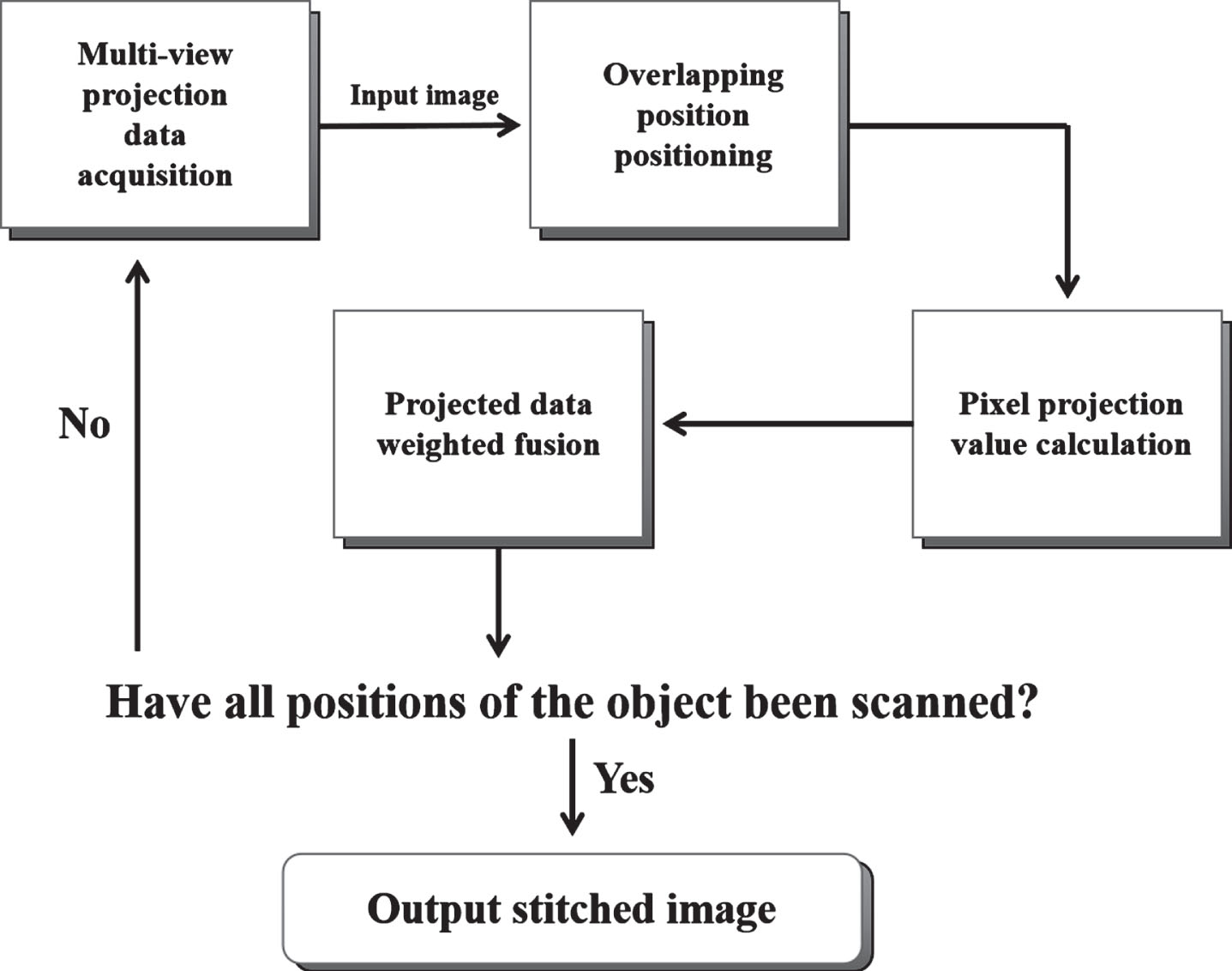
The flowchart of the proposed multi-view X-ray imaging stitching algorithm.
The multi-view projection data acquisition system designed in this paper uses the synchronous motion of a 64-pixel CdZnTe photon counting linear array detector and X-ray source to collect information from different viewing angles of fixed objects. The beam X-rays emitted by the X-ray source illuminate the linear array detector vertically. The target object is fixed to the plate, and the detector and X-ray source move parallel to the plate simultaneously, as shown in Fig. 2. After each lateral scan, the detector and X-ray source move synchronously in the direction of the arrow some distance. Before an X-ray scan is performed, it is possible to set the steps that both the detector and the X-ray source move simultaneously. Adjusting the step can change the number of fields of view used for stitching. Smaller the step results in a greater the overlap in coverage per X-ray scan.
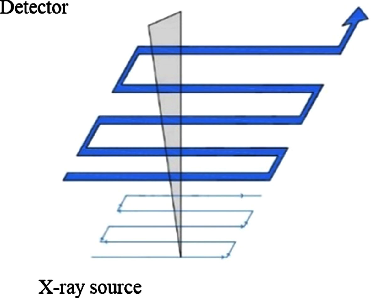
The diagram of the synchronous motion trajectory of the detector and the X-ray source.
We take a dual-view scan as an example to explain this step. The motion step of the detector and X-ray source is set to 32 pixels. This is the distance that the detector and X-ray source are moved horizontally after each scan. Figure 3 shows the acquisition process of multi-view projection data using two motion steps (32 and 16 pixels) as an example. In Fig. 3(a), we find that every two adjacent scans have a portion of overlapping areas that will help stitch the images together. The same location can be scanned up to two times, which is called dual-view scanning. Similarly, Fig. 3(b) shows a three-view scan with a motion step of 16 pixels. Projection data obtained from different perspectives is called multi-view projection data.
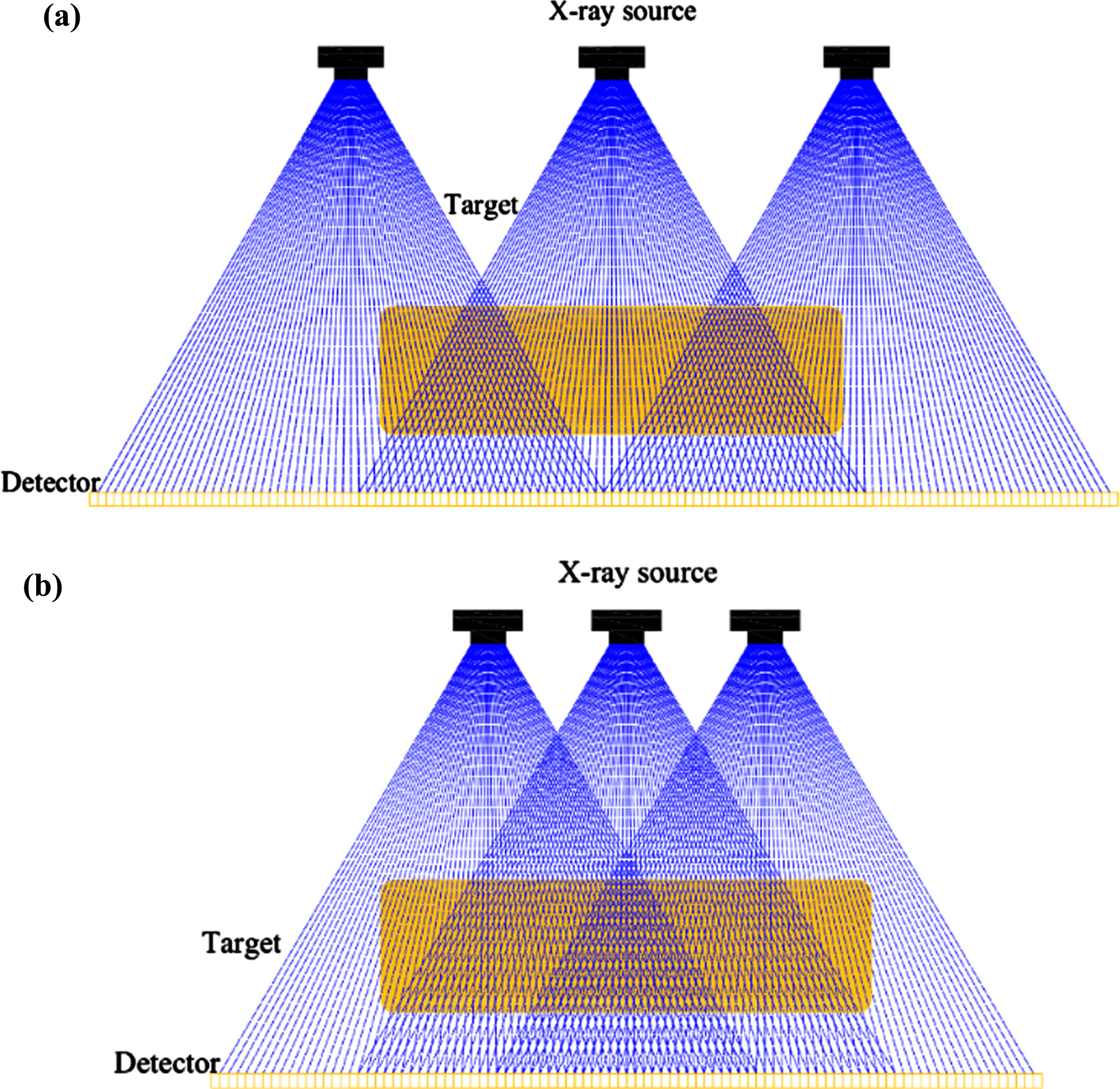
(a) The schematic diagram of dual-view projection data acquisition. (b) The schematic diagram of three-view projection data acquisition.
Because of the relatively fixed position of the detector and the X-ray source, the connection between the center position of the detector pixels and the X-ray source focus can be accurately determined. As shown by the blue line in Fig. 3, the intersection of each two connections in the overlapping area after a multi-view scan is a different depth position inside the imaged object. We establish a Cartesian coordinate system, shown in Fig. 4, where the center of the first pixels in the first scan is the origin, the horizontal direction of the pixels is the X-axis, and the direction perpendicular to the detector is the Y-axis. Every connection between the center of each pixel and the X-ray source can be expressed as follows:
Thus, the intersection coordinates of all connections in any overlapping area can be obtained as (x ij - mn , y ij - mn ), where x ij - mn and y ij - mn represent, respectively, the horizontal and vertical coordinates of the intersection. At this point, the intersection positions in all overlapping areas can be positioned to obtain the depth information inside the imaged object.

The schematic diagram of the established Cartesian coordinate system.
In our method, the projection value of each overlapping area is obtained by processing multiple sets of data from multi-view scans using a weighted fusion of the projected data. The connection to the center of each intersection and its corresponding pixels form a triangle. As shown in Fig. 5, the intersection position projection is the complete interaction of the projection of both pixels, so the projection value of the intersection position can be determined by the projection value of the two pixels. In our method, the fan beam X-ray projection is approximated to obtain the same result as that of the parallel light projection. As can be seen from the Fig. 5, as the projection line AC is closer to vertical, the projected data is closer to the actual value of the parallel light projection, so it should be assigned more weight. Thus, the formula for the weighted fusion projection data is as follows:

Weight allocation schematic for projected data fusion.
All the information inside the imaged object can be obtained by the above steps. Using the horizontal coordinates of the intersection and the size of the pixels, the pixels to which each intersection should belong are calculated. The result comprises multiple intersections that belong to the same pixel, and the projection values of each pixel can be obtained using the projection values of each intersection as follows:
This section describes in detail the experiments performed to verify the method’s performance. The custom-built experimental system is shown in Fig. 6. The X-ray source is an XRB011 (Spellman, Germany) with a maximum tube voltage of 80 kV. A 64-pixel CdZnTe photon counting linear array detector was used to complete the experiment. The detectors, produced by Imdetek Ltd., were based on CdZnTe crystals grown by the modified vertical Bridgman (MVB) method. The pixels of this detector are 0.9 mm×1.8 mm in size and spaced 0.1 mm apart. All electrodes were fabricated by Au using the evaporation deposition method. Figure 7 shows the count rate curve of this detector. Regions with loss counts below 20% in the CdZnTe photon counting detector are the linear regions of the count rate. The power of the X-ray source is fixed. The maximum tube current decreases with increases in the tube voltage. The tube voltage should not be too small. Otherwise the X-rays will not penetrate the object. When the tube voltage is fixed at 60 kV, the detector operates in the linear region within the range indicated by the red frame in Fig. 7. To obtain a good imaging performance, the detector needs to work in the linear region, and a larger the tube current leads to a clearer image. Therefore, the tube voltage and tube current selected in our experiment was 60 kV and 1.0 mA, respectively. The distance from the detector to the X-ray source was 760 mm. The X-ray source and detector movement were moved by synchronous belt transmission. The algorithm proposed in this paper performs automatic image stitching of data from the detector on a computer connected to the detector. The motion step of the detector and X-ray source was set to 32 pixels for the dual-view stitching of two objects: a globe and one foot. The globe was also imaged by a Lunar (GE, USA).
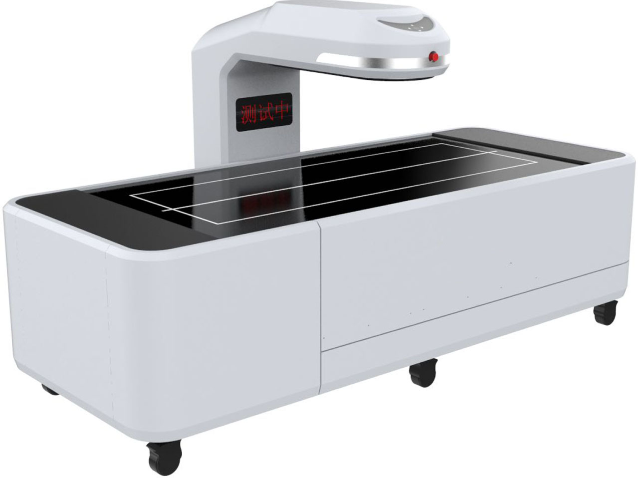
The custom-built X-ray imaging system based on linear array detectors.

The count rate curve of the CdZnTe photon counting detector (60 kV).
The globe, which is 30 cm in diameter, is shown in Fig. 8. This globe has a motor inside and three support columns below. Based on theoretical analysis, objects with large thickness differences have a greater degree of deformation in the stitched image. And this globe has a layered structure that contains a wealth of information such as outer circles, inner circles and support columns, which could better demonstrate the stitching effect of the algorithm. The outer circle of the globe can be directly observed, but other internal information, such as the inner circle, is obtained through X-ray imaging. Thus, the globe is chosen as an experimental object. First, preprocessing similar to a parallel light projection (overlapping pixel averages) was used to process the data collected by the dual-view scan. Next, a method that manually changes the movement step to adjust the position of the stitched pixels and then averages the projected values was also used to process the images. The dual-view data was also processed to obtain stitched images using the algorithm proposed in this paper. The stitched images obtained by each algorithm were compared with the original images. Finally, the projection data of this foot was collected by the custom-built system using the dual-view scanning method. The multi-view X-ray digital imaging stitching algorithm was used to stitch together the dual-view scan image of this foot, and the results demonstrate that this algorithm can be practically applied.

The actual object of the globe.
Figure 9 shows a dual-view scanned image output without any stitching. The figure shows that the deformation of the globe image when compared with the real object is severe. The circular globe has been deformed into an oval, and the positions of the edges and the interior, which should be arcs, have become many sharp protrusions. Although the internal motor is not originally round, its shape has also changed. In addition, the three cylindrical pillars have also lost their original shape. Figure 10 shows the globe image stitched together with the overlapping pixel averaging methods. Although this method corrects the ellipse to a circle, most bumps remain. The degree of imaging light and shade in the sectoral area is still quite different from the actual situation. Image distortion remains and high image stitching quality has not been achieved.

The original image of the globe scanned by the dual-view.
Image of the globe stitched by the method of overlapping pixel averages.
Figure 11 presents a stitched image obtained when the step is changed to 9 pixels. Although the stitching of concentric circles inside the globe is perfect, its edge deformation is even more significant. Figure 12 presents a stitched image obtained when the step is changed to 40 pixels. The deformation of the outer edge in the globe image disappears, but the deformation in the interior cannot be ignored. We conclude that adjusting the step only solves the imaging quality of partially stitched positions.
Image of the globe stitched by adjusting the position of the stitched pixels (9 pixels).
Image of the globe stitched by adjusting the position of the stitched pixels (40 pixels).
Figure 13 shows the stitched image of the globe obtained using the proposed multi-view image stitching method. The edges and interior of the globe are stitched together simultaneously. The shape of the globe in the stitched image is close to the actual globe shape, and the sharp distortions in the original image have been eliminated. In addition, the stitching deformation of the motor and the three support columns has also been solved. However, the brightness and darkness of the edges in the image are not uniform. Figure 14 shows the image of the globe we scanned with the Lunar.
Image of the globe stitched by the multi-view X-ray digital imaging stitching algorithm.
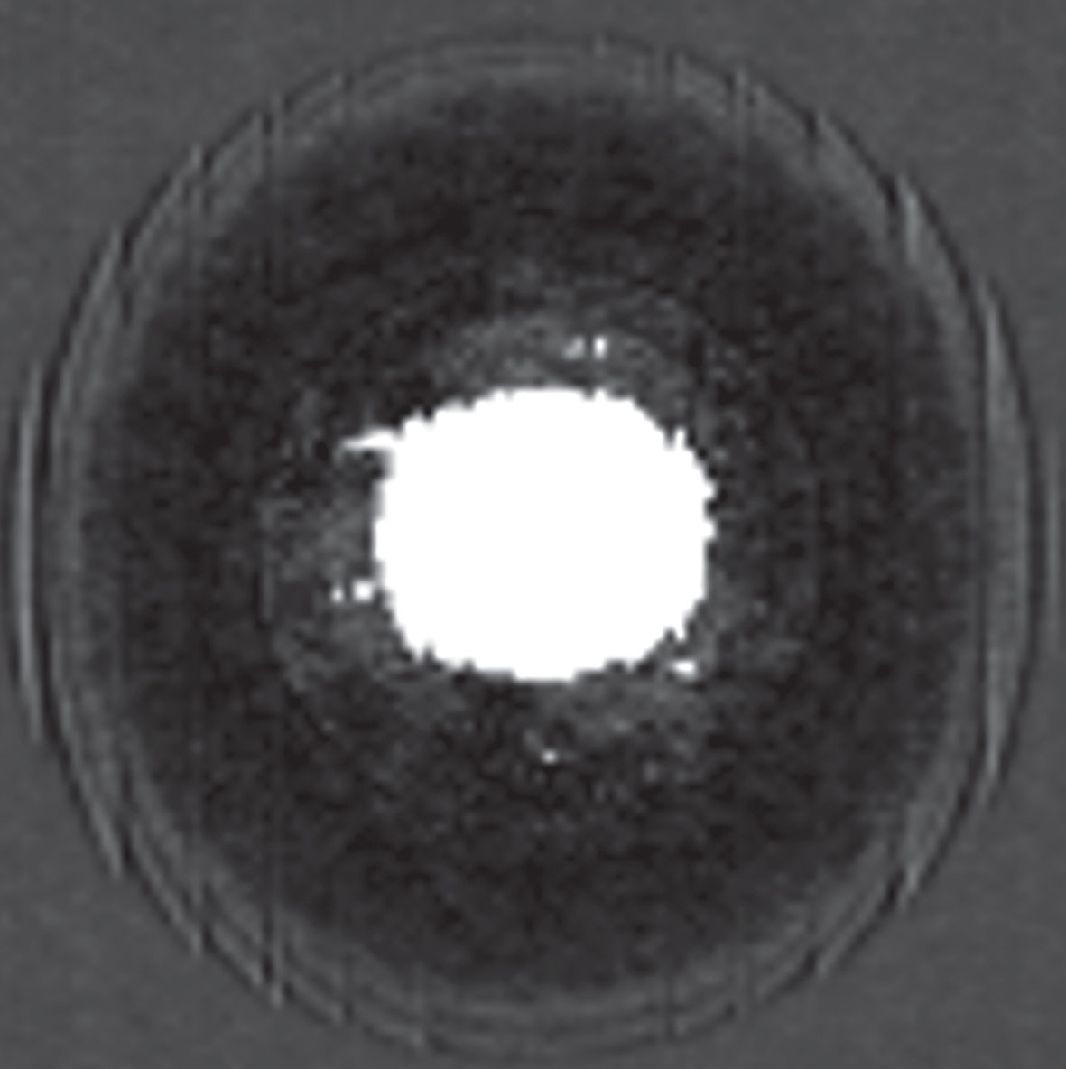
Image of the globe stitched by the Lunar.
Special cases such as globes are rare in practical medical applications. To further evaluate the application of this stitching algorithm in the field of medical imaging, images of a foot were stitched to reconstruct the final image. Figure 15 shows the X-ray imaging results of the foot before and after stitching together by the multi-view X-ray digital imaging stitching algorithm. There are many distortions in the original image, some of which are marked with red circles. The bones are not stitched together in the magnified view, which could deteriorate the image quality enough to affect a doctor’s diagnosis. Deformations in the same part in the stitched image are not preserved. Moreover, the thicker part of the image is not clear because the dose was not sufficiently high.

Comparison of X-ray images of the foot: the original (top) and the proposed algorithm (bottom).
Through the analysis of the raw data of the image, we propose to quantify the stitching quality with the difference of the stitching position count value. In the experiment, the adjacent 8 pixel count values of the image stitching position were recorded, and the gradient change of the count value at the deformation position was greater than 5%. Random sampling of several stitching algorithms at the stitching position (36 samples), and samples with a gradient change of less than 5% in the count value were considered correct stitching. Table 1 shows the correct stitching measurement of the four stitching methods. This multi-view stitching algorithm has a correct rate of 94.4 %, and the other methods have a correct rate of only about 50%.
Comparison of the accuracy of different stitching algorithms
The cause of fan beam X-ray imaging deformation was found by analyzing the imaging principle of fan beam X-rays. Figure 16 illustrates the problem. The blue line represents the incident X-ray, and parallel light and fan beam light illuminate the exact position of the target object in different directions The fan beam light projection amplifies the image object compared to the parallel light projection, resulting in the detection of the projection information at the incorrect detector pixel position, which can cause problems such as overlapping internal points and missing parts of the structure. We found that a thicker target object or one that is closer the imaged object is to the edge pixels when using the fan beam leads to a greater degree of image distortion. However, these problems do not exist in parallel light imaging.
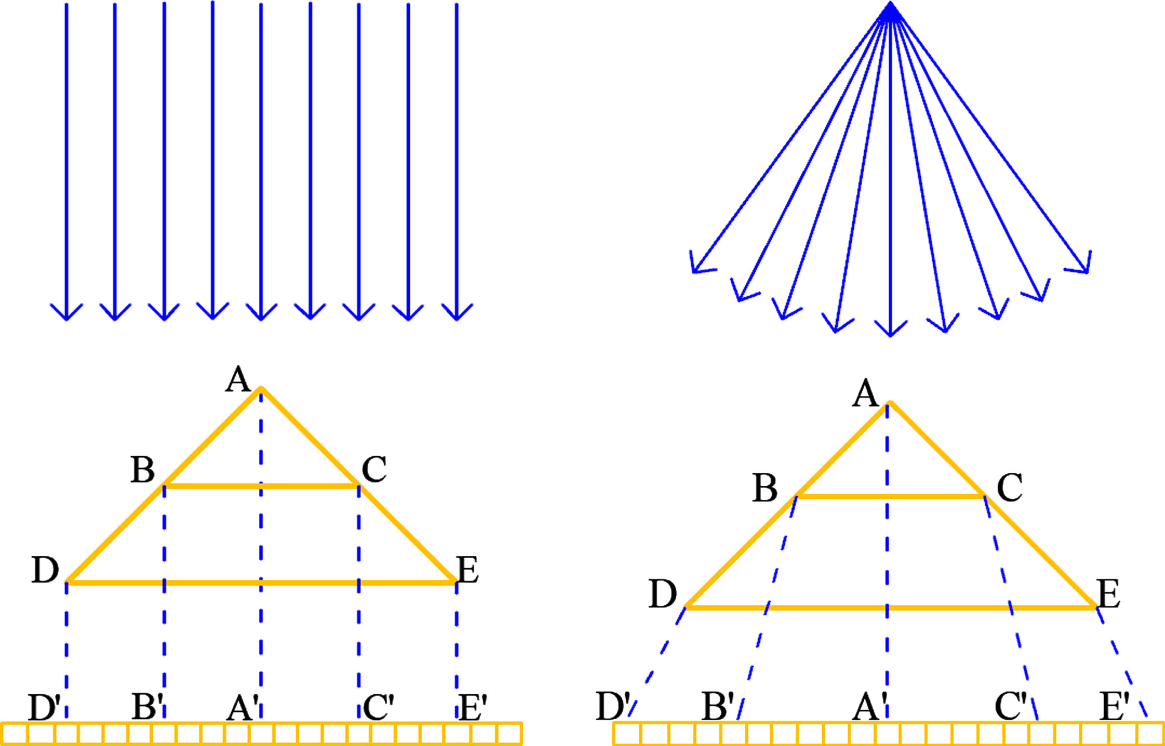
Parallel light and fan beam X-ray projection contrast schematic.
Manually moving the image stitching position does not get good stitching results. The reason for this shown in Fig. 17. The green areas in the figure represent the overlapping areas of the two scans, and the red areas are the scan “dead” zones. Figure 17 clarifies that increasing the number of stitched pixels leads to more overlapping areas, causing external distortion. Reducing the number of stitched pixels creates larger stitching blind spots, which lose some information about the imaged object. In addition, this method is mainly based on experiment and the experience of stitching, and is not universal. When the thickness of the object changes, the moving step changes accordingly. To solve the problem of stitching deformation, obtaining the depth information of each position inside the object is essential.
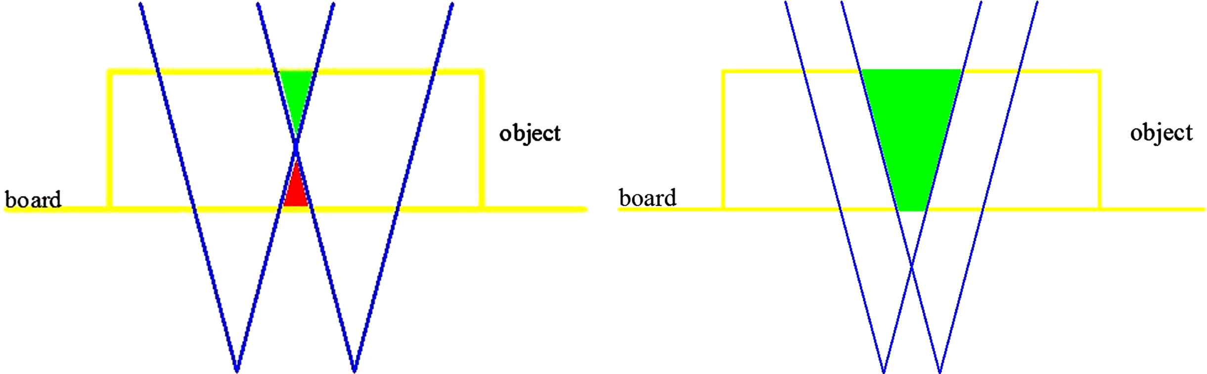
Overlapping areas and blind spots of X-ray scans with different movement steps.
The stitched image of the proposed algorithm is obtained when the scan is completed, because the stitching calculation has already been performed during each scan. Both comparison methods stitch the image after the scan has been completed. Therefore, the proposed algorithm can obtain the complete stitched image faster. Compared with the original image and images stitched using the comparison methods, the quality of the image stitched by the proposed method has been clearly improved.
The globe image obtained by the proposed algorithm is not perfect. According to the imaging principle of the photon counting detector, brighter pixels indicate that more photons have been detected. There are pixels at the edge of the globe image that have collected X-rays that have not been attenuated by the globe. The characteristics of the outer edge of the globe cause the projected values of these pixels to participate in some weighting processes. This increases the pixel count at some edges, resulting in unevenness. Compared with the Lunar scanned images, it can be seen that the imaging results of the proposed algorithm have the same level of quality as the images of state-of-the-art equipment. In terms of the globe image stitching alone, the images our algorithm produces have even higher resolution and uniformity.
The result of the proposed method demonstrates the correctness of the above analysis and the feasibility of this algorithm in practical applications. The proposed algorithm corrects the beam X-ray imaging to achieve the same imaging result as an image taken with parallel light. The entire stitching process is carried out automatically on the computer during the multi-view scanning so that the stitched image is obtained immediately after the scan has been completed.
This algorithm is not limited to dual-view scanning and the specific system described in the paper. However, when more fields of view are selected, the number of movement steps decreases, increasing the dose of X-rays on the patient in medical applications. To minimize the dose and obtain better imaging results, we can adjust the X-ray beam size used by the X-ray source. For example, when scanning the three-view, we can adjust the X-ray fan beam to illuminate only the middle 32 pixels, and then use the proposed algorithm to stitch the images. Because of the smaller angle of the fan beam, the deformation is reduced, and better imaging results are obtained. In general, this is unnecessary, and dual-view scanning can meet the needs of most applications. We can also solve the problem using this approach if a higher precision application is required.
A novel multi-view X-ray digital imaging stitching algorithm was proposed to solve the problem of fan beam X-ray imaging stitching deformation based on the CdZnTe photon counting linear array detector. The algorithm includes four steps: multi-view projection data acquisition, overlapping position positioning, weighted fusion, and projected pixel value calculation. The superiority and feasibility of this algorithm was demonstrated in X-ray imaging applications. By obtaining information about the different depths inside the object for stitching together the projection image, this algorithm can eliminate the deformation generated by the projection of the fan beam X-ray and effectively reconstruct the physical object in the image. The algorithm proposed in this article can obtain a stitched image immediately after scanning, and it has good flexibility that is not limited to the system of this paper. Moreover, using our method can balance accuracy with radiation dose.
The proposed algorithm should be further optimized. When imaging some specially shaped objects, uneven phenomena will occur at the edges of the reconstructed images of the imaged objects. Although this is rare in practical applications, the problem may be solved by pairing this algorithm with an edge recognition algorithm in future.
Footnotes
Acknowledgments
This work was supported by funds from the National Natural Science Foundation of China (61874089), the Guangdong basic and applied basic research foundation (2021A1515012558) and Science, Technology and Innovation Commission of Shenzhen Municipality (No. CJGJZD20210408091402006), Natural Science Basic Research Program of Shaanxi (Program No.2022JQ-411).