
Abstract
Abstract
A typical organic waste, petroleum drill cuttings containing hydrocarbons, heavy metals, and chlorides, was treated by stabilization/solidification (S/S) using cement and high carbon fly ash. Analytical techniques, including differential scanning calorimetry, Fourier transform infrared spectrometry/microspectroscopy, and scanning electron microscopy with energy dispersive X-ray microanalysis, were used to investigate the effect of drill cuttings on binder hydration products, the interaction between binders and drill cuttings, and the type of immobilization mechanism occurring. Results show that both high carbon fly ash and drill cuttings addition decreased the amounts of binder hydration products. Hydrocarbons were discovered to be physically trapped by micro- and macroencapsulation in the matrix formed by binder hydration. Chemical interaction was observed between binders and chlorides leading to Friedel's salt formation. Differential scanning calorimetry and Fourier transform infrared analysis of residues from leaching test indicated that exposure of S/S products to leaching conditions could compromise their integrity. This work demonstrates use of these techniques to investigate the interactions between a waste and binder during S/S, thus aiding the development of an effective S/S system.
Introduction
Stabilization/solidification treatment of drill cuttings
An important aspect of the effectiveness of S/S is the effect of the waste components on the formation of the binder hydration products that are responsible for the desired properties of the S/S product. The main products from cement hydration include portlandite (calcium hydroxide), calcium silicate hydrate (C-S-H), and aluminate/sulfoaluminate phases (Taylor, 1997; MacLaren and White, 2003). The addition of waste may completely inhibit their formation, alter the quantities formed, or may lead to the formation of new products. The binder hydration products can be studied using thermal techniques such as differential scanning calorimetry (DSC) and microstructural techniques such as Fourier transform infrared (FTIR) spectrometry and scanning electron microscopy (SEM) coupled to an energy dispersive X-ray (EDX) spectrometer.
Thermal and microstructural analytical techniques
DSC determines the various phase transitions occurring in a material subjected to a programmed temperature variation. Although thermogravimetry and differential thermal analysis are more common, the use of DSC for pure cement systems or those containing inorganic compounds has been reported. Moukwa et al. (1992) used DSC to determine the amount of calcium hydroxide formed in hydrated cement paste. Abdelrazig et al. (1992) used DSC to show that monochloroaluminate was formed during cement hydration due to the presence of calcium chloride. Sha et al. (1999) used DSC to study the thermal behavior of hydration products in Portland cement and reported the presence of four products: C-S-H, ettringite, calcium hydroxide, and calcium carbonate. Qiao et al. (2007) determined the effect of heavy metals on S/S systems using DSC and reported that metal hydroxides negatively affected the formation of calcium hydroxide.
FTIR spectrometry can be used to characterize the microchemistry of materials, and can therefore provide information on the physical and chemical interactions between two or more materials. Some publications have reported its application to cement systems containing admixtures; for example, Ben-dor and Perez (1975) studied the influence of CaCl2, CdI2, and CrCl3 on the hydration reaction of cement minerals using FTIR and reported that these compounds resulted in the acceleration of binder hydration. Mollah et al. (1998) used FTIR to characterize S/S products containing arsenic and reported an interaction between oxyanions and cement particles. Although, FTIR spectrometry is an excellent technique for studying organic compounds, there is little evidence of this application in the literature. Hanna et al. (1995) studied S/S products prepared from heavy metal wastes with added organic compounds using FTIR and reported a reduction in silicate condensation due to the organic compounds. A prolongation of induction period and inhibition of hydration reaction was reported by Mollah et al. (2000) when FTIR was applied in investigating the effects of sodium lignosulfonate on cement hydration. Silva et al. (2002) also applied FTIR to confirm the occurrence of chemical interaction between Portland cement and ethylene/vinyl acetate copolymer.
FTIR has conventionally been applied to ground solid samples; however, with the introduction of synchrotron-source infrared microspectroscopy (an FTIR spectrometer coupled to an infrared microscope), it can be applied to study the microstructure and microchemistry of unground solid samples. This is particularly advantageous for S/S products, as microscale mapping involving the collection of spectra at several points across the surface of sample can be conducted. This can provide information on the distribution of the chemical component across the mapped surface, which is useful for understanding the association and interaction between the treated waste and the binder hydration products at the microscale and provides insight into the immobilization mechanism. However, no literature on the application of synchrotron-source FTIR to S/S products was found.
SEM provides data on the morphology and mineralogical characteristics of a material and, when coupled to an EDX, can further provide quantitative data on the elemental composition of the material at the microscale. SEM has commonly been used to study cements and cement-based products containing inorganic contaminants. Some publications have also reported its application in the characterization of S/S systems containing organic compounds. Eaton et al. (1987) used SEM/EDX for the investigation of interferences between organic compounds and cement hydration products. Skipper et al. (1987) applied SEM/EDX in the analysis of Portland cement paste containing parachlorophenol. Montgomery et al. (1991) used SEM/EDX to study the interaction between cement and organic compounds, whereas Natali Sora et al. (2002) used SEM to study the chemistry and microstructure of cement paste mixed with organic liquids.
Aims and objectives
This work aims to investigate the interaction between petroleum drill cuttings and hydraulic binders in S/S products prepared with Portland cement and high carbon fly ash (HCFA). HCFA was used in the S/S process as it contains carbon that could potentially serve as sorbent for organic contaminants, to immobilize them and prevent the detrimental effect of organic compounds on binder hydration. Specifically, the work investigates the mechanism of contaminant immobilization in S/S drill cuttings, and the effect of drill cuttings and HCFA on binder hydration, using DSC, FTIR spectrometry/microspectroscopy, and SEM/EDX microanalysis. S/S products subjected to leaching were also characterized using DSC and FTIR spectrometry to gain insight into the changes that might occur in S/S products when exposed to environmental conditions, for example, in a disposal or reuse scenario.
Materials and Methods
Raw materials
Oil-based petroleum drill cuttings were obtained from an unidentified terrestrial drilling operation and were characterized as described in previous work (Leonard and Stegemann, 2010a), including hydrocarbon, metal, and chloride contents. They contain predominantly C12 to C32 aliphatic hydrocarbons in concentrations ranging from <1 to 140 mg/kg, heavy metals in concentrations ranging from <1 mg/kg to 5% (Ba), and >6,000 mg/kg of chloride. Ordinary Portland cement, CEM I 42.5N, conforming to EN 197-1:2000 was used, along with HCFA obtained from an unidentified source. The composition and characteristics of the drill cuttings, CEM I, and HCFA are summarized in Table 1.
HCFA, high carbon fly ash; L/S, liquid-to-solid ratio.
Sample preparation
S/S products prepared for a factorial design experiment to assess treatability of the drill cuttings by S/S with different proportions of CEM I and HCFA, but a constant water-to-solid ratio of 0.45 (Table 2) was used in this study. Results of physical and chemical tests, including specific gravity, bulk density, unconfined compressive strength (UCS), hydraulic conductivity, porosity, acid neutralization capacity, and hydrocarbon, metals, and chloride leaching are reported elsewhere (Leonard and Stegemann, 2010a, 2010b). Measured quantities of drill cuttings, CEM I, HCFA, and water were homogenized in a Hobart mixer, poured into 50 × 50 mm steel cube molds, compacted using a vibrating table, sealed in plastic bags to prevent carbonation, and then cured in a humidity chamber at a relative humidity of 98% ± 2% and temperature of 21°C ± 3°C, before testing. Fragments from the 7- to 56-day UCS tests were dried in an oven at 60°C for 6 h to stop binder hydration, after which thermal and microstructural analysis were conducted.
Control samples.
Thermal and microstructural tests were also conducted on the untreated drill cuttings, as received, and on dried residues obtained from 24 h batch leaching tests conducted on the S/S products according to EN 12457-2:2002 (apart from SEM/EDX).
Thermal and microstructural analysis
Differential scanning calorimetry
The untreated drill cuttings, dried S/S products, and EN 12457 leaching residues were ground to pass a 150 μm sieve. The changes in the characteristics of the ground samples as a function of increasing temperature were studied using a TA Instruments DSC Q100 calorimeter. Duplicate analyses were conducted on samples weighing between 10 and 20 mg packed and sealed in an aluminum pan, at a heating rate of 10°C/min under flowing nitrogen gas (30 mL/min) and temperature ramping from 60°C to 550°C. Powdered alumina was used as the reference sample. Analysis of the DSC curves was conducted using TA Instruments Universal Analysis software.
FTIR spectrometry
FTIR analysis of the untreated drill cuttings, dried S/S products, and the EN 12457 leaching residues was performed using a Thermo Nicolet Nexus 670 FTIR spectrometer coupled to a Globar infrared source. Optically transparent discs were prepared by grinding and thoroughly mixing ∼0.01 g of each of samples with ∼0.2 g of predried potassium bromide. About 0.02 g of the mixture was then compressed in a mini-press to form the transparent discs. Infrared spectra were collected within the region of 4,000 and 400 cm−1 with a spectral resolution of 4 cm−1 and aperture size of 100 μm. To ensure an acceptable signal-to-noise ratio, 128 scans were collected for each sample. Air was used as the background spectrum. To understand the association and distribution of organic compounds within the drill cuttings, and of drill cuttings within the binder matrix, at the microscale, chemical mapping of untreated drill cuttings and S/S products was carried out with the synchrotron source infrared microspectroscopy beamline at the J. Bennett Centre for Advanced Microstructures and Devices, Louisiana State University, Baton Rouge, LA, using a Thermo Nicolet Continuum infrared microscope equipped with a nitrogen-cooled mercury-cadmium telluride detector and interfaced with the synchrotron source infrared beamline (Kizilkaya et al., 2005). Line mapping spectra of untreated drill cuttings spread evenly on a mirror placed on the computer-controlled microscope stage and of polished flat S/S specimen were recorded in the reflectance mode with a gold mirror used for background correction. Spectra were recorded between 4,000 and 650 cm−1, with an aperture size of 30 × 30 μm and map stage step-size of 20 μm, with 256 scans collected for each point.
SEM/EDX microanalysis
Micrographs and EDX spectra of untreated drill cuttings and polished fractured surfaces of S/S products were collected using a Hitachi S-4500 II cold field emission SEM instrument coupled to an EDX microanalyzer equipped with a compact detector unit. SEM imaging was carried out at an operating voltage ranging between 10 and 20 kV and an emission current of 16 μA.
Results and Discussion
DSC analysis
The DSC curve for untreated drill cuttings, which shows qualitative heat flow curves as a function of temperature, is presented in Fig. 1. Features of the curve indicate physical or chemical transitions in response to heating. Four distinct peaks, AD, BD, CD, and DD, were observed. Peak AD, from 50°C to 130°C, can be assigned as the loss of moisture from the drill cuttings. Peaks BD and CD, from 130°C to 150°C, and 150°C to 240°C, respectively, can be assigned as the volatilization of light hydrocarbon fractions, while peak DD, from 460°C to 550°C, possibly represents the thermal breakdown of clay mineral, kaolinite, or other components of drill cuttings such as hydrated lime.
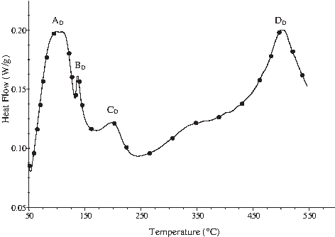
Differential scanning calorimetry scanning of untreated drill cuttings.
DSC analyses were carried out on the control samples and S/S products after 7 and 56 days curing. The DSC curves after 56 days curing are presented in Fig. 2. The curves for the 7 days S/S products are similar but vary only in size. Four distinct peaks, ED, FD, GD, and HD, were observed. The two joint peaks ED and FD, from 50°C to 130°C, have been reported to be a result of stepwise loss of water molecules from C-S-H (Sha et al., 1999). However, it is possible that the first peak could be a result of evaporation of remnant moisture content of the sample, whereas the second peak could be assigned strictly to C-S-H dehydration. Peak GD, from ∼140°C to 190°C, indicates the presence of ettringite (Sha et al., 1999), whereas peak HD, from ∼425°C to 500°C, represents the dehydroxylation of calcium hydroxide (Abdelrazig et al., 1989; Sha et al., 1999). S/S products prepared with CEM I:HCFA at a waste:binder ratio of 3:2 also show a peak ID from ∼310°C to 350°C, which was not detected in the other products. A similar peak had been observed in cement paste mixed with calcium chloride by other researchers (Abdelrazig et al., 1992; Suryavanshi et al., 1995), which they designated as chloroaluminate (i.e., Friedel's salt). Compositional analysis of untreated drill cuttings and HCFA shows that they contain chlorides and aluminates (Table 1) that could react to form Friedel's salt. The nonexistence of this peak in the other S/S products could be because it was formed at undetectable quantities, as the CEM I contains less aluminates than the HCFA. The transition temperatures were not exactly the same for all samples, which can be attributed change in the heat response characteristics of the hydration products due to the addition of drill cuttings and HCFA. A similar shift in transition temperature was reported by Suryavanshi et al. (1995).

Differential scanning calorimetry scans of stabilization/solidification (S/S) products.
By integrating the peaks in a DSC curve, it is possible to obtain the energy absorbed or evolved during a transition phase and this can be used to semiquantify the amount of hydration products produced during cement hydration, since the energy absorbed or evolved is proportional to the amount of compound present within a transition phase (Moukwa et al., 1992).
In particular, the amounts of calcium hydroxide and C-S-H produced during cement hydration give an idea of the degree of hydration. Since C-S-H is generally responsible for strength development, the amount produced can also give an idea of the mechanical and durability properties of a cement product (Stegemann and Zhou, 2009). In a Portland cement, C-S-H production will be accompanied by production of calcium hydroxide, but in a blended binder system involving a pozzolan such as pulverized fly ash (PFA), calcium hydroxide is consumed by pozzolanic reaction to form C-S-H (Pollard et al., 1991; Shi, 2004).
The relative amounts of calcium hydroxide, based on the heat evolved during DSC, are summarized in Fig. 3a. S/S products prepared with CEM I only contained more calcium hydroxide than those containing HCFA; the amount of calcium hydroxide in the CEM I-only products increased with curing, whereas it decreased in those prepared using CEM I and HCFA. These observations suggest that calcium hydroxide produced by hydration of CEM I is being consumed over time by a pozzolanic reaction to form C-S-H. Generally, all S/S products showed a significantly lower amount of calcium hydroxide than their corresponding controls, indicating inhibition of binder hydration by the drill cuttings. Analysis of variance (ANOVA, Table 3) showed these effects on calcium hydroxide content to be highly significant, with the probability that the observations occurred by chance <3%. The trends in calcium hydroxide formation are in agreement with UCS results (reported in Leonard and Stegemann, 2010a) for the S/S products, which shows decreased strength with increased drill cuttings and HCFA content.
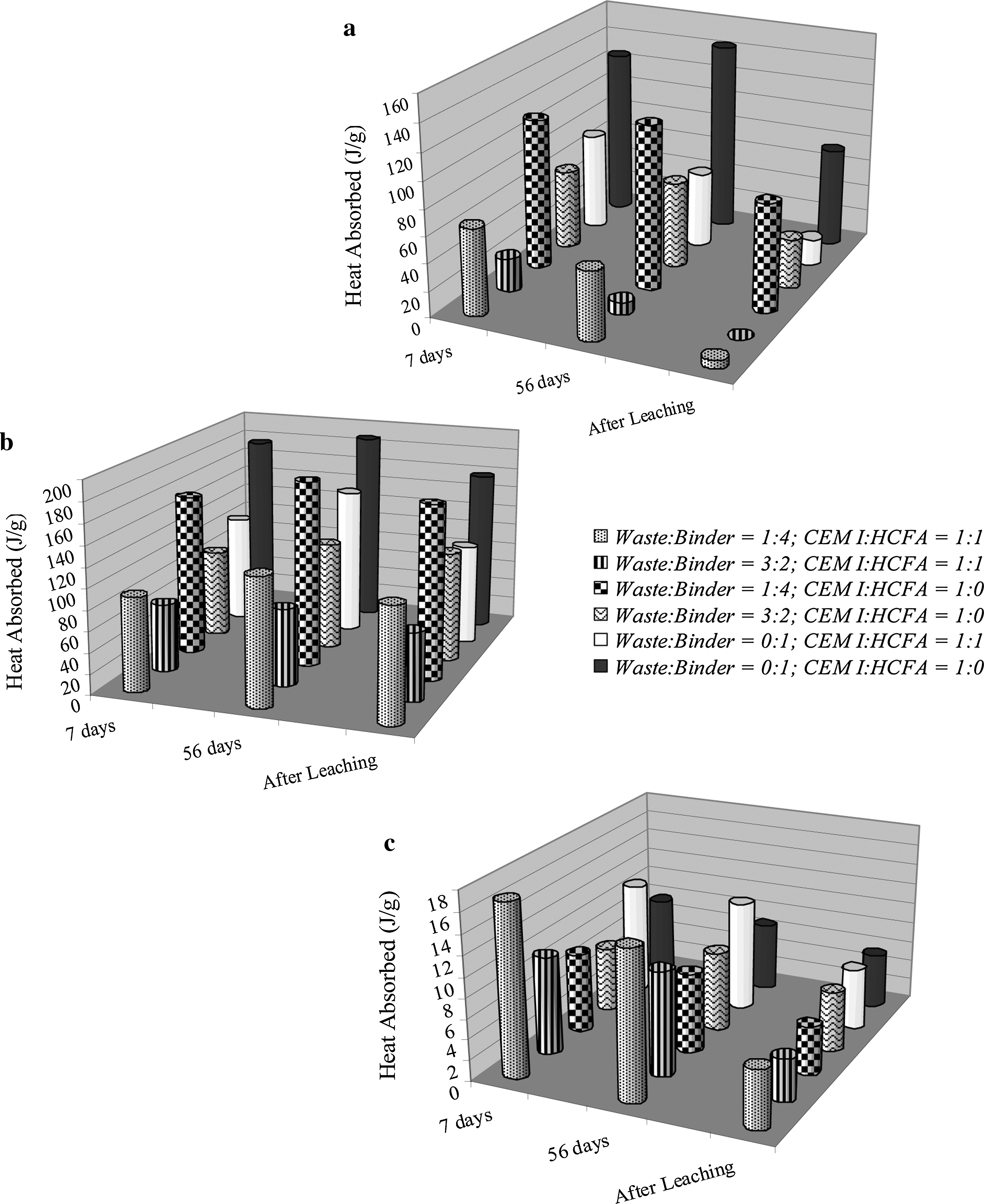
Energy absorbed due to
Figure 3b summarizes the relative amounts of C-S-H formed in the S/S products. Both drill cuttings and HCFA addition led to statistically significant reductions in the amount of C-S-H produced. A visually apparent increase in the amount of C-S-H produced with time, however, was not found to be statistically significant. In the case of drill cuttings, the reduction in amount of C-S-H is consistent with inhibition of binder hydration by the drill cuttings, but it is, nevertheless, surprising that more C-S-H was not formed over time. Likewise, slow reaction of a pozzolan such as HCFA might be expected to result in less C-S-H at early ages, but an increase C-S-H would be expected with time. Although ANOVA supported the significance of these effects (Table 3), this analysis is based on the precision of these results. However, it is possible that the accuracy of the C-S-H quantitation may be affected by the overlap of the region of DSC curve associated with C-S-H dehydration, with the region corresponding to evaporation of remnant moisture content of the samples on the DSC curves; that is, the analysis may be insufficiently accurate to allow strong conclusions to be drawn. Alternatively, the carbon present in the HCFA may actually have an inhibitory effect on binder hydration (Poon et al., 2003).
Figure 3c shows the relative amounts of ettringite formed in each of the S/S products; the data suggest that the amount formed does not change significantly with increased curing time, indicating that most of the ettringite is formed within the first 7 days of curing, and has not yet converted to monosulfate at 56 days. Drill cuttings addition does not seem to affect ettringite formation either, but HCFA seems to encourage ettringite formation. ANOVA (Table 3) yields a p-value of 0.016 for the significance of this effect. The higher ettringite formation in the HCFA products may be attributable to the composition of the binders (Table 1); compared to CEM I, HCFA contains roughly triple the amount of Al2O3, which is the main component of hydraulic binders responsible for ettringite formation in the presence of sulfate.
Integration of the DSC curves for solid residues from batch leaching according to EN 12457-2:2002 indicates a significant decrease in the relative amounts of calcium hydroxide and ettringite, in comparison with the S/S products before leaching (Fig. 3). The CEM I:HCFA products with waste:binder ratio = 3:2 show a complete absence of calcium hydroxide after the leaching; this illustrates the high solubility of this phase. Ettringite is also shown to be quite soluble, limiting its long-term potential for entrapment of anions, as has been proposed by some authors (e.g., Hassett et al., 1989; McCarthy et al., 1992).
FTIR spectrometry/microspectroscopy analysis
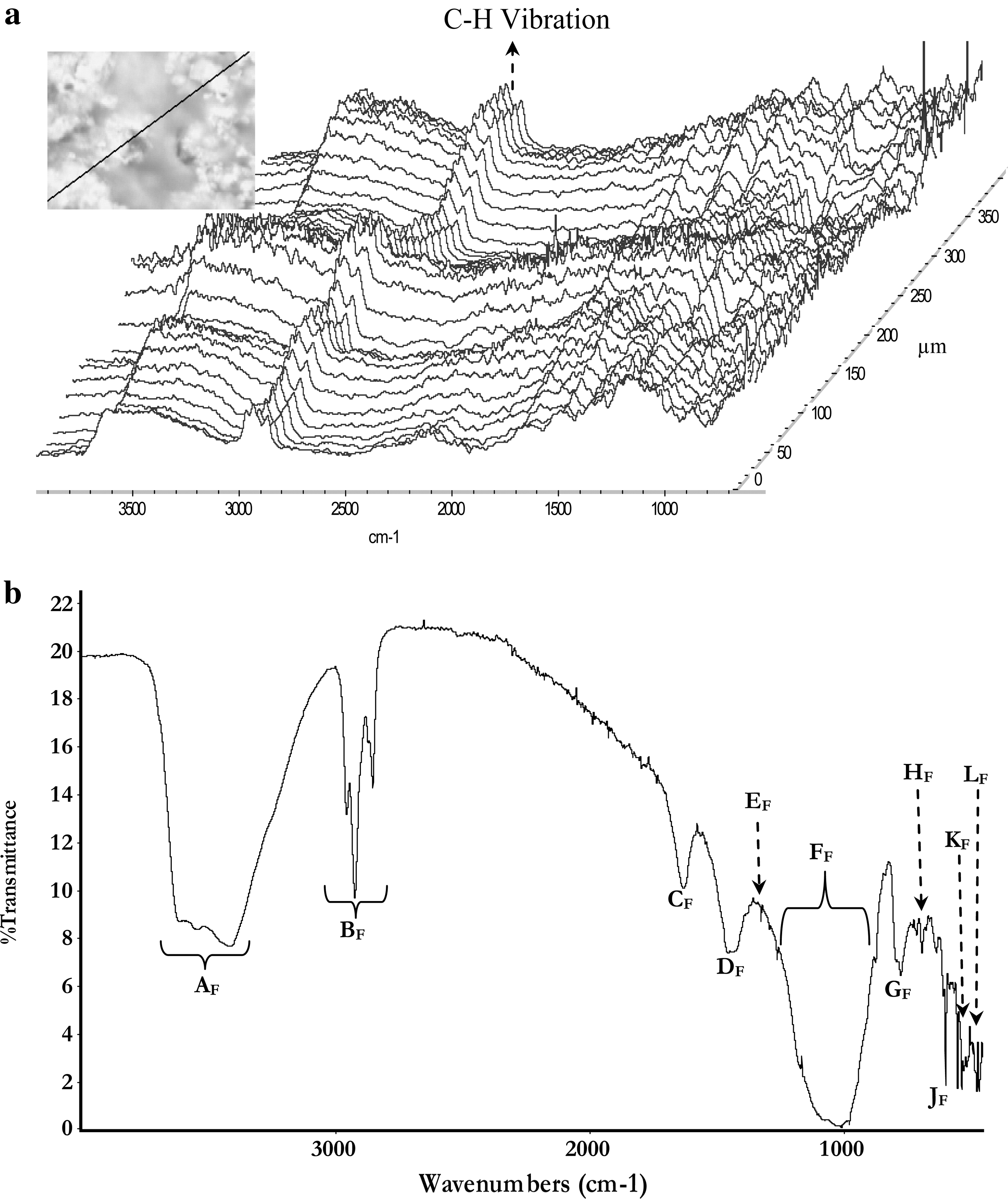
Figure 4a shows the waterfall spectra obtained from the line mapping of untreated drill cuttings using synchrotron source infrared microspectroscopy. The spectra indicate that all the components of drill cuttings are evenly distributed across the studied line, as all spectra at each point on the line map are similar; some regions, however, show stronger intensity of the C-H stretching vibration typical to organic compounds, suggesting that hydrocarbons are preferentially associated with some components of drill cuttings. These regions show strong silicate peak, expected to be from the clay content of drill cuttings, indicating a strong affinity between hydrocarbons and the clay contents. The Globar source FTIR spectrum is shown in Fig. 4b; the various bands in the spectrum provide insight into the composition of drill cuttings. The broad absorption band between 3,800 and 3,100 cm−1 (peak AF), along with the band at 1,633 (peak CF), suggests the presence of water of hydration in the clay content of drill cuttings (Stuart, 2004). However, peak AF could also imply the presence of O-H stretching vibration of clay minerals, or of oxygen-containing organic materials such as starch, cellulose, glycols, and glycerin, which are added to drill cuttings to act as lubricating agents (NRC, 1983). The adsorption band between 3,000 and 2,800 cm−1 (peak BF), together with the weak peak EF, and peak GF around 750 cm−1, corresponds to the C-H stretching vibration of methyl and methylene groups typical to aliphatic hydrocarbons (Coates, 2000; Stuart, 2004). Initial characterization of the untreated drill cuttings using gas chromatography/mass spectrometry shows that dichloromethane/acetone soxhlet extracts of the drill cuttings contain predominantly aliphatic hydrocarbons (Leonard and Stegemann, 2010a). The broad band between 1,470 and 1,370 cm−1 (peak DF) can be assigned to the carbonate content of drill cuttings. The intense broad band around 1,070 cm−1 (peak FF) corresponds to the asymmetric stretching of silicates (Si-O) from the clay content of drill cuttings, whereas the bands at 525 cm−1 (peak KF) and 460 cm−1 (peak LF) correspond to the out-of-plane Si-O bending and in-plane Si-O bending, respectively (Madejova, 2003), also from the clay component of drill cuttings. The series of bands between 700 and 600 (peak HF, IF, and JF) is typical of OH-containing organic materials such as starch, cellulose, glycols, and glycerin (Coates, 2000).
The 7- and 56-day FTIR spectra for the CEM I-only and CEM I:HCFA control samples (i.e., runs 5 and 6, respectively) are shown in Fig. 5a. The two spectra are similar except for the higher intensity of the peaks in the CEM I-only sample, which suggests that more hydration products were formed in the CEM I-only control sample and is consistent with the DSC observations. Peak MF, observed at ∼3,640 cm−1, is due to O-H stretching of calcium hydroxide (Ben-dor and Perez, 1975), whereas the broad band between 3,750 and 3,200 cm−1 (peak NF) and peak OF, centered at ∼1,642 cm−1, signifies the presence of O-H vibration of water molecules and H-OH vibration of absorbed water, respectively (Stuart, 2004). The two joint peaks around 1,500 cm−1 (peaks PF and QF) represent the C-O vibration of carbonates formed by the reaction of calcium hydroxide with CO2 (Mollah et al., 1998). Careful observation of the spectra shows the presence of a weak band around 1,140 and 1,110 cm−1 (peak RF), representing the S-O vibration of sulfate from monosulfate or ettringite (Mollah et al., 1998; Myneni et al., 1998). Peak SF at 874 cm−1 can be assigned as either Al-OH bending vibration of ettringite or C-O bending vibration due to carbonates (Myneni et al., 1998). The bands around 975 cm−1 (peak TF), 525 cm−1 (peak UF), and 460 cm−1 (peak VF), respectively, correspond to the asymmetric stretching, out-of-plane stretching, and in-plane Si-O bending vibrations of silicates from C-S-H (Mollah et al., 1998; Yu et al., 1999).
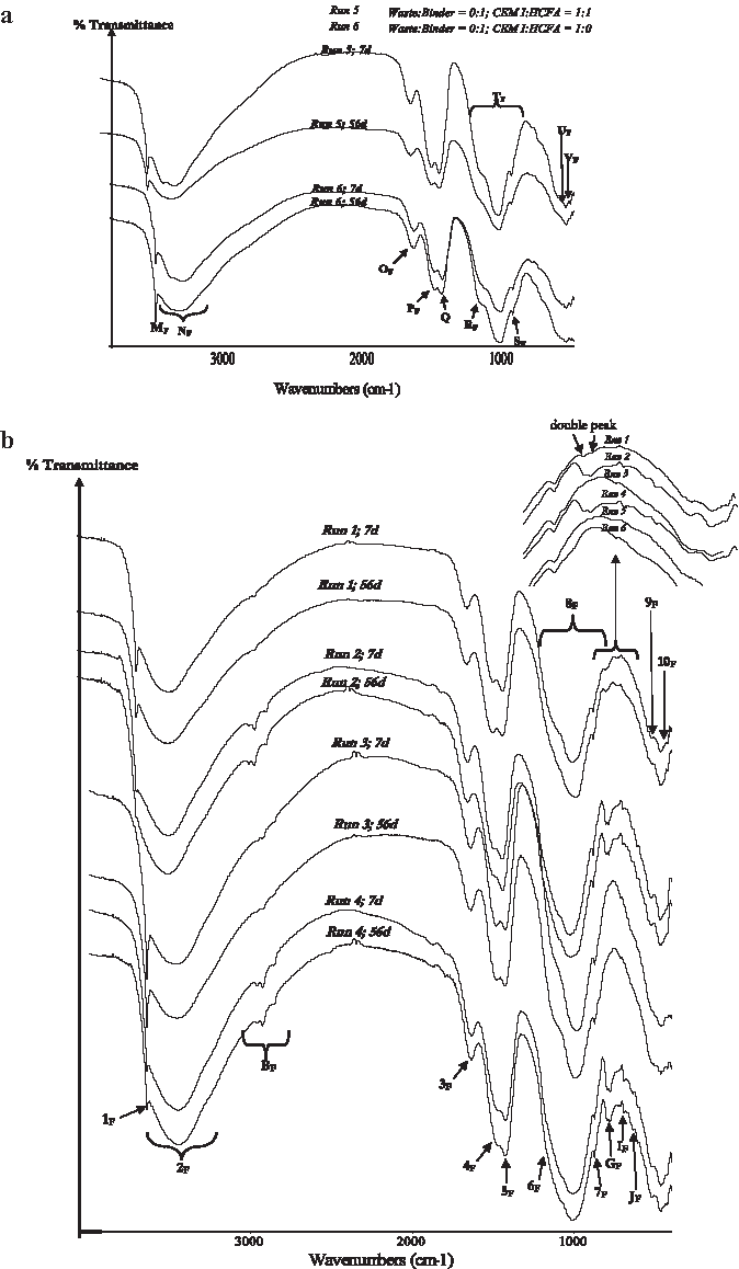
Figure 5b shows the FTIR spectra for the treated drill cuttings. The bands present were generally similar to those in the control samples except for the presence of peaks GF, IF, and JF, which were earlier tentatively identified as organic materials in the drill cuttings. However, Friedel's salt, which is expected to be formed from the reaction of binders and chlorides in the drill cuttings, normally shows a characteristic peak around 786 cm−1 (Birnin-Yauri and Glasser, 1998), which could have overlapped with peak GF. In fact, careful observation of that region (see Fig. 5b) shows the presence of a double peak that was more prominent in samples prepared at waste:binder = 3:2. As no other new peak was observed in the treated drill cuttings, it suggests that Friedel's salt formation is the only chemical interaction between the components of drill cuttings and the binders, indicating that contaminant immobilization is predominantly by physical encapsulation or adsorption.
A comparison of the calcium hydroxide peaks indicates that more calcium hydroxide was formed in the CEM I-only products than the CEM I:HCFA products, and the products with higher drill cuttings content show weaker calcium hydroxide peaks relative to the those with a lower quantity of drill cuttings. Again, these observations support the results obtained by DSC. The calcium hydroxide peak intensity increased with curing time for the CEM I-only products, and decreased with curing time for the HCFA products, which is also in agreement with DSC results.
FTIR analysis of solid residues from leaching according to EN 12457-2:2002 (Fig. 6) revealed similar changes in the calcium hydroxide peaks as a result leaching, as were observed with DSC. It was also noticed that the C-H vibration of organic compounds became more intense after leaching, which could be due to the release of binder hydration products, hence making hydrocarbon spectra more prominent. It can be inferred from this that, with continuous exposure to leaching, the physical entrapment of organic contaminants could be compromised; however, this observation also suggests that the hydrocarbons are more resistant to leaching than the hydration products. Hydrocarbons content of drill cuttings have been shown to exhibit poor leachability from the S/S products (Leonard and Stegemann, 2010b). Two new peaks (WF and XF) were noticed in the spectra of the leaching residues, and peaks RF and SF became more intense. Since these peaks were also observed in the leaching residues of the control samples, it is safe to conclude that the observation cannot be attributed to the hydrocarbon content of drill cuttings. Peak RF could be due to S-O vibration of sulfate from monosulfate or ettringite, it was noticed that the increased intensity is more prominent in CEM I:HCFA products, which is consistent with the high Al2O3 content of HCFA. Peak SF is due to either Al-OH bending vibration of ettringite or C-O bending vibration due to carbonation. The increased intensity is, however, more likely to be due to carbonation rather than ettringite formation as DSC results show a decrease in ettringite after leaching. Carbonation is known to occur when carbon dioxide reacts with either C-S-H or calcium hydroxide in the presence of water (Saetta et al., 1993). Slegers and Rouxhet (1976) reported the same intense FTIR peak due the carbonation of tricalcium silicate; they designated this peak as vaterite, a polymorph of calcium carbonate; they also reported a small band similar to the new peak XF reported here at around 714 cm−1, which they attributed to the formation of aragonite, another polymorph of calcium carbonate.
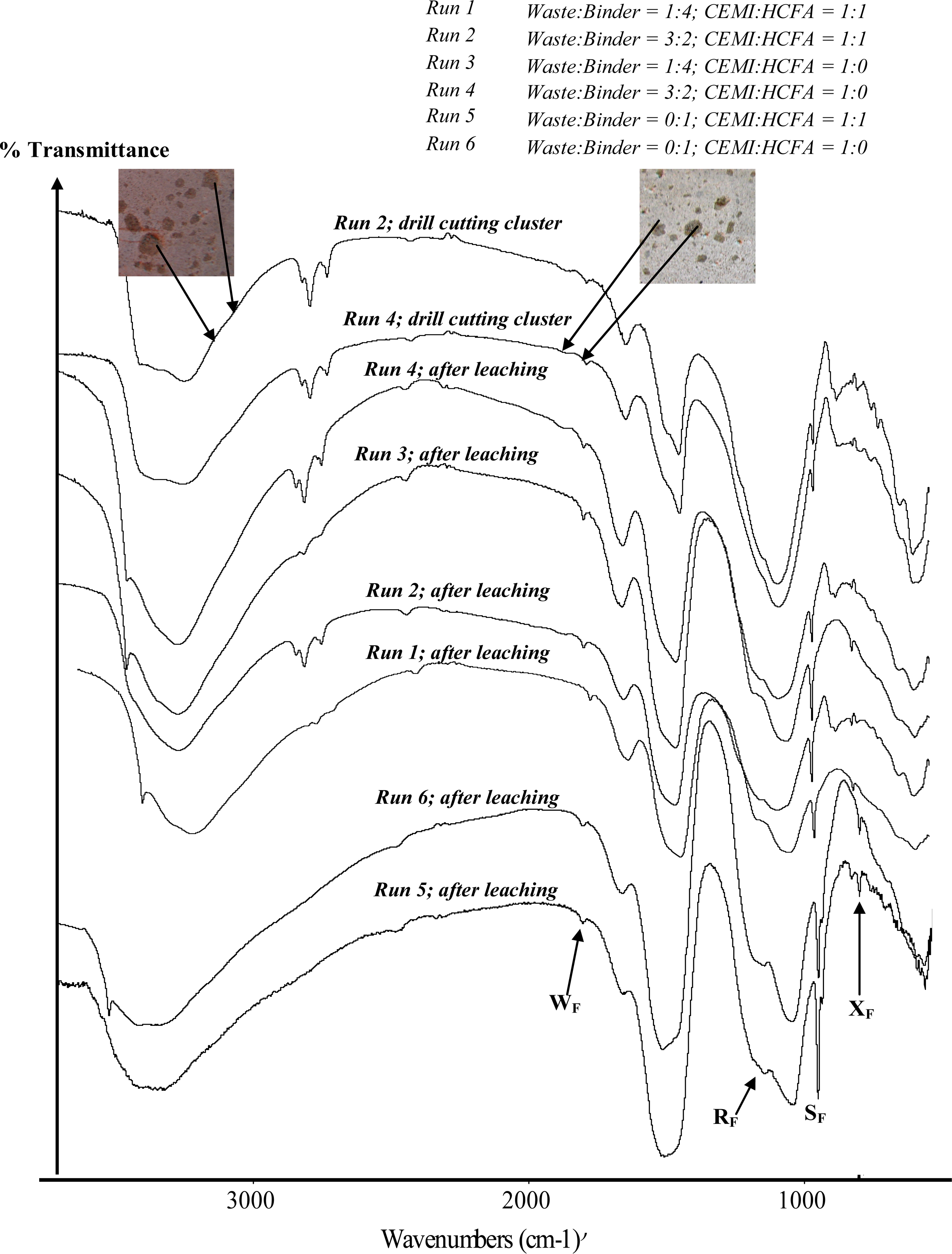
IR spectra for S/S products (drill cuttings cluster and after leaching).
Physical observation of the S/S products shows that there are clusters of drill cuttings macroencapsulated within the hydrated binder (Fig. 6), which illustrates the extreme difficulty of achieving adequate mixing of the oily drill cuttings. FTIR analyses of these clusters (also in Fig. 6), however, show a weak carbonate or ettringite peak (SF) indicating interaction between the binders and the drill cuttings within these clusters. Except for peak SF, the spectra resembled those of the untreated drill cuttings, further supporting the general absence of a chemical interaction between drill cuttings components and binders. Synchrotron source FTIR mapping across a line of 400 μm length on a polished surface of a typical S/S product shows a nonuniform contour plot (Fig. 7a), indicating nonuniform binder hydration across the S/S product due to the interaction between drill cuttings and the binders. Spectra from selected regions of the line map (Fig. 7b, c) revealed the existence of regions with a spectrum similar to that of the control samples and others having the characteristic C-H peak BF typical of hydrocarbons, providing further evidence of the microencapsulation of drill cuttings within the binder hydration products. The hydrocarbon regions also suggest the association and sorption of hydrocarbon content of drill cuttings onto the binder hydration products or in the case of HCFA samples, the hydration products and the unburnt carbon of HCFA. This is, however, inconclusive because of the impracticability of differentiating between the C-H peak due to drill cuttings or that due to hydrocarbons adsorbed onto binder hydration products or unburnt carbon. However, results obtained from sorption tests show a high affinity between aliphatic hydrocarbons found in the drill cuttings and HCFA, and FTIR microspectroscopy confirms a preferential adsorption of these hydrocarbons onto the unburnt carbon of HCFA (Leonard et al., 2010). It seems likely that the drill cuttings and associated hydrocarbons are physically encapsulated by the cement hydration products, but that mobility of the hydrocarbons from the encapsulated regions is further limited by sorption.
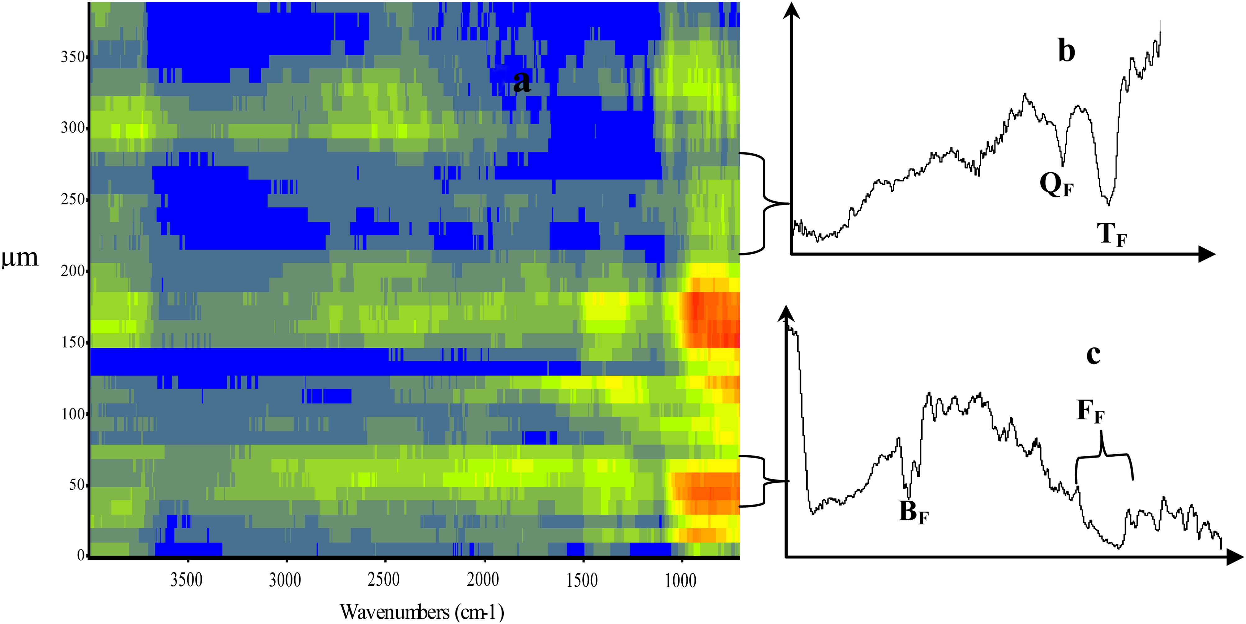
Synchrotron source IR microspectroscopy line mapping across the surface of a typical S/S product:
SEM/EDX microanalysis
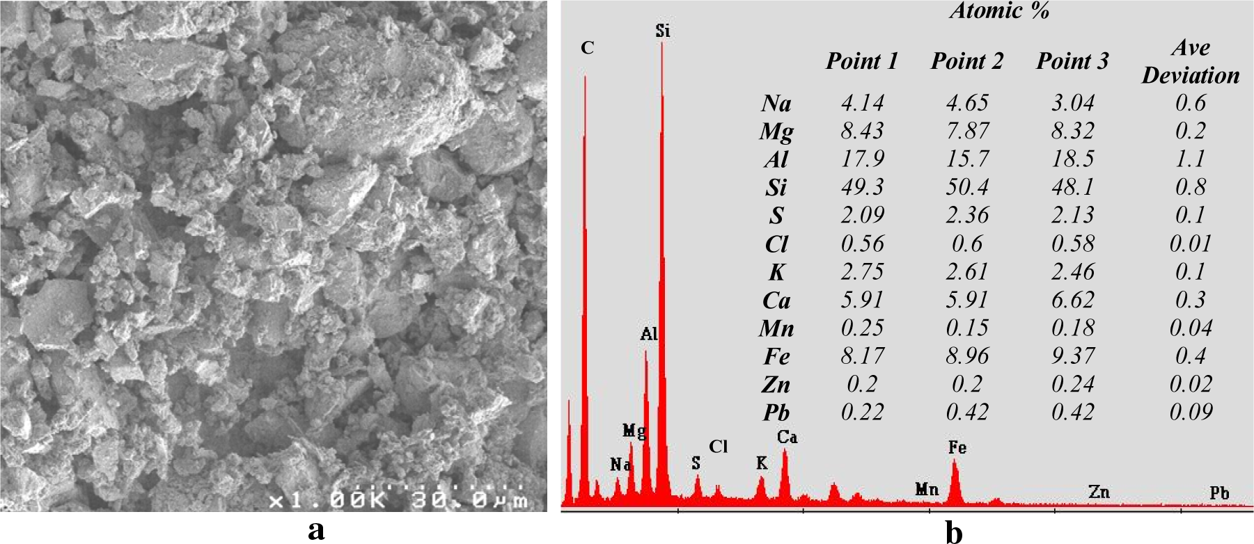
An SEM micrograph and the corresponding EDX spectrum for the untreated drill cuttings are shown in Fig. 8a and b, respectively. They show that drill cuttings are composed of grains of clayey materials, with silicon as the predominant element. The EDX result supports the previous conclusions that the components of drill cuttings are evenly distributed, as elemental analysis across different points had an average deviation of <1.2% for all elements.
SEM micrographs of the CEM I-only samples and CEM I:HCFA controls are presented in Fig. 9. Except for the presence of unreacted fly ash grains observed in the latter, their morphologies were basically the same, showing the presence of C-S-H, calcium hydroxide, and ettringite. EDX analysis conducted on different spots for each sample shows that the addition of HCFA to the CEM I led to a decrease in the Ca/Si ratio calculated from the atomic percentages of each element at the spots where EDX data were taken. While CEM I-only samples show Ca/Si values ranging from 2.1 to 3.2, those for CEM I:HCFA samples ranged from 1.1 to 1.5. This variation in Ca/Si ratio within the same sample could be an indication of the formation of different types of C-S-H.
SEM micrographs of control samples.
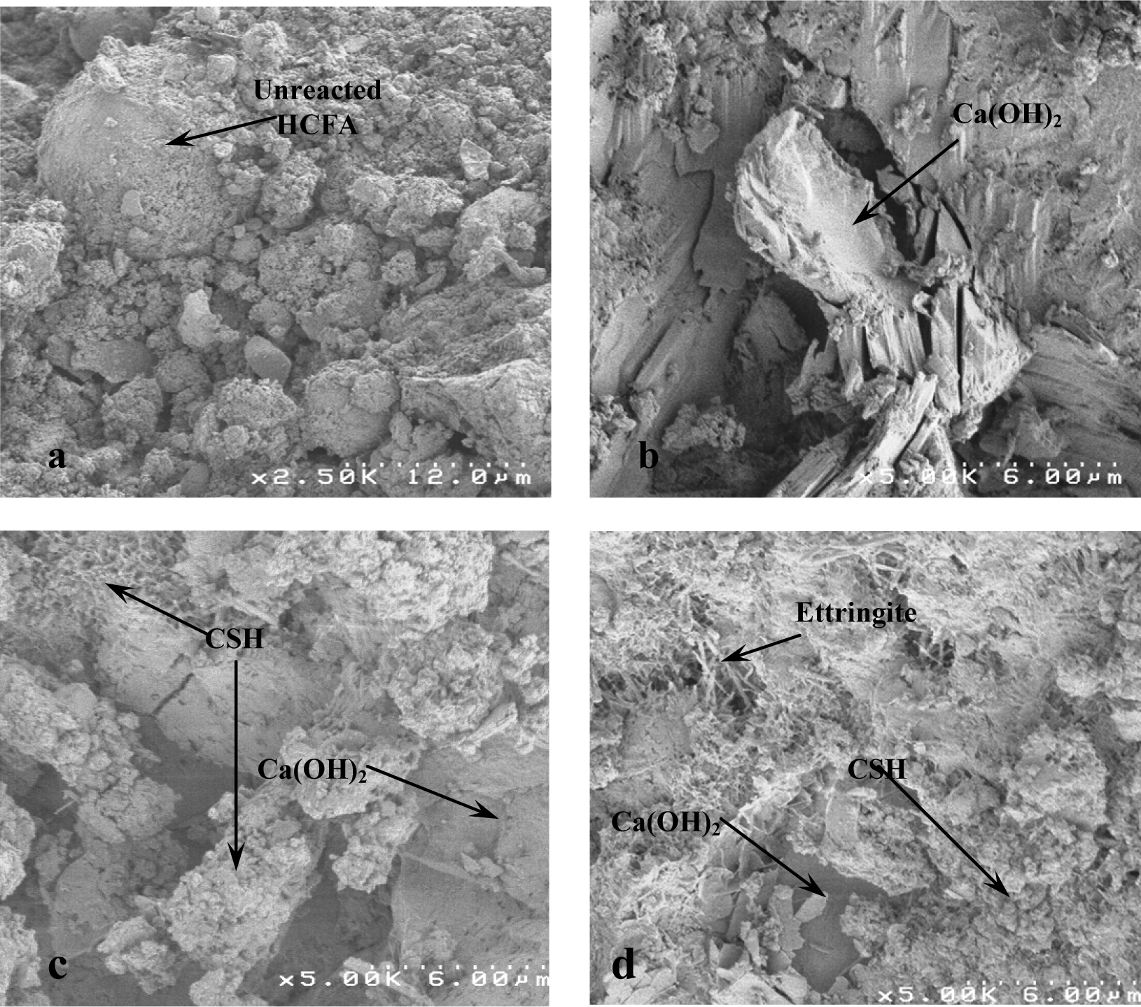
Figure 10 shows the SEM micrographs for the treated drill cuttings, which show the presence of similar hydration products as were found in the control samples, including C-S-H, calcium hydroxide, and ettringite in all samples, and unreacted fly ash in the samples prepared from CEM I:HCFA. They also show regions containing grain-like aggregates, which EDX microanalysis confirmed to be microencapsulated drill cuttings. Some regions also had a chloride concentration above that in the untreated drill cuttings, and a dissimilar composition of other elements in the untreated drill cuttings; these are therefore suspected to contain Friedel's salt (Fig. 10i) already confirm to be present via DSC.
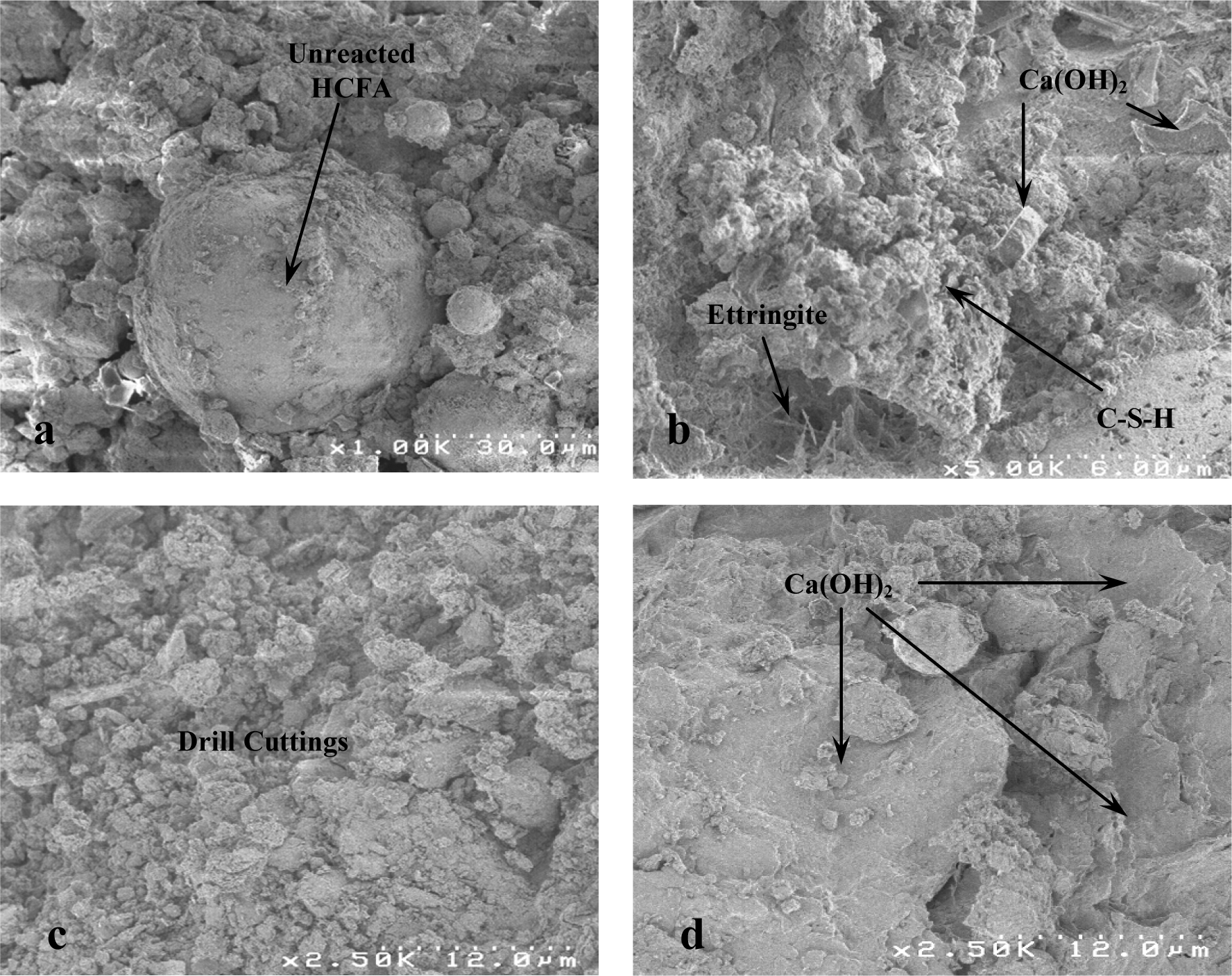
Selected SEM micrographs from treated drill cuttings:
Conclusions
To investigate the effectiveness of S/S in the treatment of petroleum drill cuttings, and to understand the interaction between drill cuttings and the cement-based binder, thermal and microstructural analyses were carried out on S/S drill cuttings. The following conclusions can be drawn from the results:
Cement and HCFA treatment of petroleum drill cuttings led to the formation of binder hydration products, including C-S-H, calcium hydroxide, and ettringite. Analysis also suggests the formation of Friedel's salt due to the chloride content of the drill cuttings. DSC and FTIR results indicate that the quantity of hydration products was reduced by addition of either HCFA or drill cuttings; HCFA was assumed to undergo slow pozzolanic reaction, whereas the oil content of drill cuttings led to an inhibition of binder hydration.
Apart from the reaction between binders and the chloride content of drill cuttings, results obtained did not show any other form of chemical interaction. FTIR and SEM/EDX analysis of clusters of drill cuttings observed in a matrix of cement hydration products suggested that the main contaminant immobilization mechanism is physical encapsulation, though sorption of contaminants that migrate out of the drill cuttings regions into the matrix may also occur. Analysis of residues from batch leaching of S/S products shows a decrease in the amount of binder hydration products and increased intensity of hydrocarbons demonstrates the relatively high solubility of calcium hydroxide and ettringite and the affinity of hydrocarbons for the solid phase.
Footnotes
Acknowledgments
The first author wishes to thank the UK Natural Environment Research Council and Scottish Power, UK, for financial support via the Dorothy Hodgkin Award Scheme. We also wish to acknowledge the J. Bennett Johnston, Sr., Centre for Advanced Microstructures and Devices, Louisiana State University, Baton Rouge, LA, and the UK Quality Ash Association, and specially thank Dr. Lindon Sear, Dr. Varshni Singh, Dr. Orhan Kizilkaya, Oblesh Jinka, and Kiet Nguyen.
Author Disclosure Statement
The authors declare that no conflicting financial interests exist.