
Abstract
Abstract
The aim of this article was to investigate the environmental noise effects of different median barrier shapes in the presence of a plain roadside noise barrier. A two-dimensional boundary element method was used to calculate the insertion loss of different profiled barriers over a frequency range of 50–4,000 Hz. Erecting a 1-m plain median barrier in the middle of a 40-m-wide highway has shown a considerable reduction in efficiency of a 3-m plain roadside barrier. From this point, different profiled median barriers were designed to reduce the negative effects of median barriers. It was found that sloped barriers with 10° compared with other profiled barriers have better efficiency. Comparing the overall results of tested models, the best performance improvement related to the reference barrier was seen in the barrier model “KAI” by 1.41 dB (A).
Introduction
On the other hand, median barriers as an erected structure in highways are often designed to prevent cross-median crashes (Donnell and Mason, 2006). Longitudinal median barriers may be rigid, semirigid, or flexible (Donnell and Hughes, 2005). Although the necessity of median barriers for vehicles is known, these can also be defined as a new noise source. The performance of the roadside barrier could be affected by placing a median barrier, which depending on the various designed models could alter the efficiency of insertion loss. However, Martin and Hothersall (2002) have studied the median barriers in conjunction with roadside barrier and reported a consistent improvement in insertion loss of between 1 and 2 dB over the range of conditions considered. Note that the median barrier is considered as a noise barrier in the work by Martin and Hothersall (2002), whereas in the present investigation the median barrier is studied as an extra surface that results in different consequences.
Further, median barrier along with a roadside barrier as the second used barrier in a highway can act like the parallel roadside barriers. The only difference is related to their heights, which can lead to different results. Studies on parallel barriers are continued from 1984 (Bowlby, 1984) to present (Monazzam and Nassiri, 2009a, 2009b), whereas the study on the acoustic efficiency of median noise barriers is not considered same as parallel barriers.
In this study, the performance of a plain rigid roadside barrier with and without a rigid median barrier is surveyed. Then, various median barrier shapes are designed to decrease the negative efficiency of a plain median barrier.
Materials and Methods
In the present study, boundary element method (BEM) is considered an effective tool to predict the acoustic efficiency of different barrier models. BEM was developed in the 60s and has been extensively used (Baulac et al., 2008). Numerous applications of BEM for prediction of acoustic performance of noise barriers have shown the good accuracy of this method (Watts et al., 1994; Ishizuka and Fujiwara, 2004; Monazzam and Lam, 2005, 2008; Baulac et al., 2007, 2008).
As shown in Fig. 1, BEM is a two-dimensional (2D) method that consists of two axes (x, y). The horizontal axis lies in the ground and the y axis is perpendicular to the ground plane. γ is the cross-sectional surface of the noise barrier on the ground.
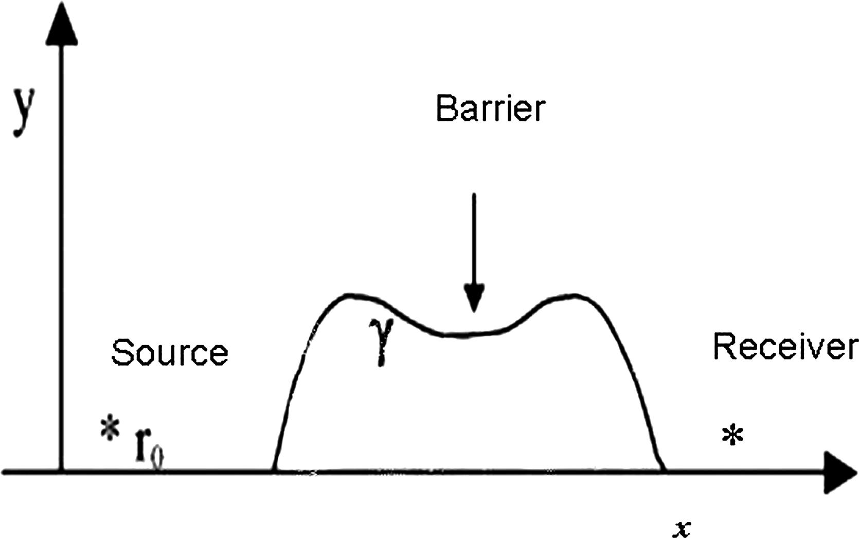
Two-dimensional model.
A uniform line source is at r0 = (x0, y0) and the sound pressure at r is p(r, r0). In this method, the boundary of each element is divided into a number of straight line elements (γ1, γ2, … , γn), where the acoustic pressure p(r0, rn) is assumed to be constant over each element. To present a reasonable representation of constant surface pressure over an element, the dimension of elements is taken to be less than λ/5 (Hothersall et al., 1991a). Note in this study that the dimension of element was 8 mm, which is less than 1/10 of the shortest tested wavelength. Based on this estimation, the following integral equation was introduced by Helmholtz:
where ∂s (rs) denotes the length of an element of γ at rs;
In a rigid ground plane, G(r, r0) is the acoustic pressure at r due to the source at r0, which could be estimated as
where
More details of this method were presented by Ishizuka and Fujiwara (2004).
In all tested barriers, to reduce the interference between the source and its ground image, the sound source is located near ground at coordinate (5, 0.02). The sound pressure with and without considering the noise barrier at 1/3 octave band between 50 and 4,000 Hz is predicted at different receiver positions. Note that in all tested models the ground is taken to be rigid.
Thus, according to this method, insertion loss at each frequency is computed by
where pb is the pressure with both the ground and barrier present and pg is the pressure at the receiver with only the rigid ground present.
Results and Discussion
Combined effects of plain median barrier with roadside barrier
The performance of a plain roadside barrier with and without the median barrier is predicted at 15 receiver positions including −5, −10, −20, −50, and −100 m from the center line of the roadside barrier on ground and at heights of 1.5 and 3 m above ground. As shown in Fig. 2, roadside barrier is a plain barrier located at a 20-m distance away from the median barrier, where the overall height was fixed at 3 m to be consistent with previous studies (Fujiwara et al., 1998; Monazzam and Lam, 2008). In this study, the roadside barrier, namely barrier model “I,” was used for coordination on every occasion.

The overall height of the plain median barrier was 1 m, which is typically used in literature. The thickness of barrier model I and barrier model “HAI” was 0.2 and 0.15 m, respectively. Note that all surfaces admittance of tested shapes was zero, which means these surfaces were reflective.
To investigate to what extent the median barrier reduces the efficiency of a roadside barrier, the A-weighted mean insertion loss of barrier model I (without any median barrier) was compared with the barrier model HAI (the effect of roadside barrier along with the median barrier as shown in Fig. 2) at 15 receiver positions (BS EN 1793-3, 1998).
As expected, the performance of barrier model HAI was significantly lower than that of barrier model I at almost entire receiver points, as shown in Table 1. The difference value varied from 1.12 dB in receiver point (−10, 1.5) to 2.79 dB in receiver point (−100, 1.5). Also, one more important result that can be derived by averaging the results at these 15 receivers was that erecting the median barrier along with the roadside reduces the insertion loss by 2 dB (A). This result confirmed the study on parallel noise barriers by Watts (1996). Hence, the rest of this article tries to design different new median barrier shapes to reduce the negative effect of the plain median barrier in barrier model HAI. From now onward, barrier model HAI was considered to be the reference barrier for comparison with new introduced barrier shapes.
IL, insertion loss.
Efficiency of different median barrier models
To define distinctly the characteristics of studied barriers, Table 2 has shown the description of all models. Moreover, the structural dimensions of a few different median barrier shapes that have been used in the simulations are presented in Fig. 3. To provide a similar condition for a precise comparison, the overall height and stem thickness of all median barriers similar to barrier model HAI were kept to be 1 and 0.03 m, respectively. More specifically, in profiled barrier, the angle and length of each part of the caps were 60° and 0.15 m, respectively. Further, the angle of the sloped barriers was fixed at 10°. This angle was used, because in most previous studies a higher efficiency of 10° relative to other sloped degrees was verified (Watts, 1996; Monazzam and Nassiri, 2009b).
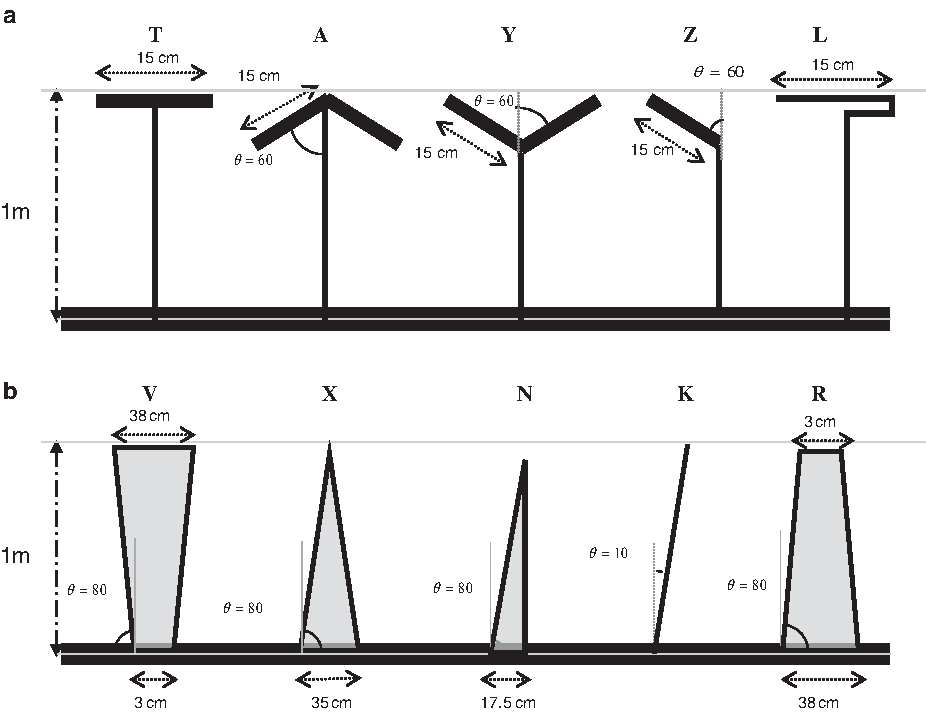
It should be mentioned that the only difference between barrier model HAI and other tested models is the shapes of median barrier, as other conditions such as receiver positions and roadside barrier model remained unchanged.
Figure 4 displays insertion loss difference of two profiled barriers including barrier models “LAI” and “TAI” related to their equivalent plain median barrier (barrier model HAI) when the receiver was located at point (−10, 0). The overall trends were the same for both models because of their similar shapes. The only insertion loss improvement of barrier models LAI and TAI was found at midfrequencies and at a frequency of 3,150 Hz. As a result, the A-weighted traffic noise spectrum of barrier models LAI and TAI at receiver point (−10, 0) was lower than that of the reference barrier.
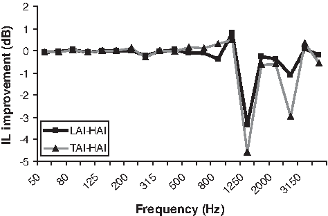
IL difference of barrier models “LAI” and “TAI” compared with reference barrier at receiver point (−10, 0). IL, insertion loss.
The condition of median barrier along with a roadside barrier was the same as when parallel barriers were erected in highways. Constructive and deconstructive effects of incident and reflected waves between two barriers make negative and positive acoustical effects. Thus, in this case, the constructive effects of incident and reflective waves for these special shapes were similarly responsible for the negative efficiency at entire frequency bandwidth.
Comparison of insertion loss of the other profiled barriers including barrier models “AAI,” “YAI,” and “ZAI” with their equivalent plain barrier (the reference barrier) is shown in Fig. 5. Frequency selectivity of these three models was due to the constructive and destructive effects of incident and reflected sounds, which can be altered based on the wavelength of the wave and the geometry of the barrier. It can be clearly seen from the graph that the efficiency of all the three aforementioned models get close to each other and that these models reduce the negative insertion loss of the reference barrier within a frequency range of 500–1,000 Hz. Hence, as the dominant frequency of highway traffic noise was mostly within this range, these barriers could be a good option to be replaced with barrier model HAI. The peaks of barrier model AAI compared with barrier models YAI and ZAI were higher, that is, around 500 to 800 Hz, and this can be explained by the π/2 phase difference between the image of roadside barrier and the wave reflected from the lower edge of “arrow” shape. As a result, the best correspondence of destructive effect will occur at a frequency of 630 Hz. Also, with a change in conjunction point of reflection wave to median barrier at frequencies 500 and 800 Hz, a phase difference of π/2 would happen, which makes a destructive effect. Cancelouting the multiple reflection effects due to the angle of the source side branch of these barriers provides a significant attenuation at frequencies 2,000 and 3,150 Hz.
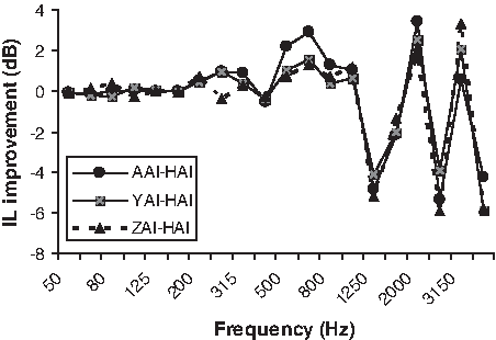
IL difference of different profiled barriers including barrier models “AAI,” “YAI,” and “ZAI” compared with the reference barrier at receiver point (−10, 0).
In this study, investigations were also performed in both far and near field (2,500 receiver points) behind barrier model AAI compared with its equivalent plain median barrier at 500 Hz. A set of calculations were made from 2- to 50-m distance from the roadside barrier and from ground level to a height of 10 m. As the most dominant frequency of highway traffic noise is around 500 Hz, the efficiency of barrier model AAI was tested in this frequency and then the amount of change in insertion loss was plotted in Fig. 6. The efficiency of barrier model AAI compared with reference barrier was seen across a wide area of near zone both close and above the ground, although this improvement at higher elevations close to the barrier was more considerable. Wave cancellation due to the distance between the source and erected screens is a good reason to explain the cross line in the figure in which different distances and locations of screen, source, and median barrier as well as various heights of the barriers show various performances.
The amount of improvement in IL of barrier model “AAI” related to that of reference barrier at 500 Hz in the wide field behind the roadside barrier.
In this investigation, sloped barriers were also tested to study the reflective wave effects on the roadside noise barrier. In this case, different tilted median barriers were designed. First, barriers with the same source side designs and different lower construction material including barrier models KAI, NAI, and XAI were compared with the reference barrier, and second, the barrier models RAI and VAI with same construction material but different source side angles were considered.
The acoustic performance of the first condition was compared with their equivalent plain barrier at receiver position (−10, 0), as shown in Fig. 7. The source side of these three models helps the wave to be redirected upward. Removing the multiple reflections between median and roadside barriers employing tilted median barrier makes only negative performance at frequencies 1,250, 1,600, and 2,500 Hz.
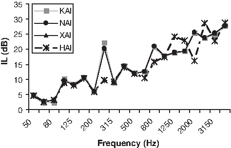
Predicted frequency spectra of IL for three different sloped barriers along with reference barrier at the receiver point (−10, 0).
Wave cancellation deconstructive effect of incident and reflected sound waves of sloped barriers at the tested receiver location explain the positive insertion loss at predicted frequency spectra. For instance, as the reflection waves from the real median barrier edge and its image have a phase difference of π/2 at a frequency of 250 Hz, a destructive effect occurred. Moreover, the construction material has no considerable role in acoustic performance of titled barriers because it seems that the improvement of these tilted barriers related to barrier model HAI was related to the geometrical condition of the barrier (Fig. 7). It should be mentioned that all the sloped barriers were tilted toward the opposite side of roadside barrier by 10°.
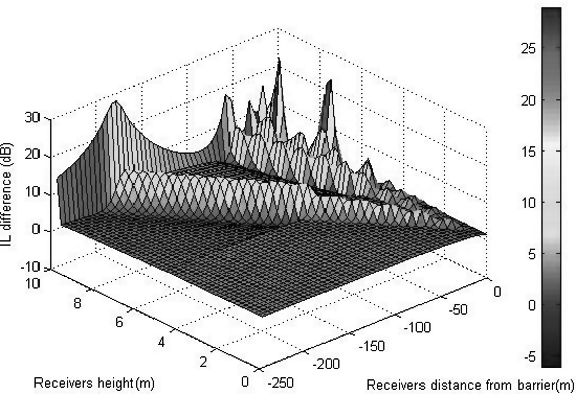
The amount of performance improvement made by the barrier model KAI in a wide area behind the roadside barrier relates with its equivalent plain barrier, as shown in Fig. 8. The performance of barrier model KAI in the near field to 10-m distance from the barrier at higher heights was considerable, which produces 16.23 dB (A) higher insertion loss than the reference barrier, although the constructive effects of the incident and reflected waves make the insertion loss reduction in some parts of that zone. It can be seen that the improvement at zones close to ground was the same as that in the far field.

The amount of improvement in IL of barrier model “KAI” related to that of reference barrier at 500 Hz in the wide field behind the roadside barrier.
In Fig. 9, the performance of the second condition of sloped barriers (barrier models RAI and VAI) were compared with the reference barrier. It was found that the difference in facing angles of barrier models VAI and RAI change the behavior at the frequency spectra. The incident wave in barrier model RAI, similar to the tested barriers in Fig. 7, was reflected upward while the reflected waves in barrier model VAI was redirected downward. The same angle of the source side branch of barrier model RAI with barrier models NAI, XAI, and KAI makes similar destructive effect as well. In other words, the reason for the improvement around 200–315 Hz was due to the phase difference of π/2 between reflection waves from the real median barrier edge and its image. In the particular condition, redirecting the incident wave upward is more helpful than conducting it downward, although, by inclining a barrier, the power of multiple reflections and the diffuse energy components will decrease (Cheng and Ng, 2001). This is the reason that the mean A-weighted insertion losses of all sloped barriers were higher than that of profiled barriers in this investigation.
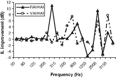
Difference in IL of barrier models “RAI” and “VAI” compared with reference barrier at receiver point (−10, 0).
Broadband insertion loss
In Table 3, the computations of mean A-weighted traffic noise spectrum of the aforementioned barriers over 15 different receiver locations at 1/3 octave band was presented using the British Standard Method (BS EN 1793-3, 1998). First, the broadband insertion losses of investigated models were averaged at the 15 receiver positions and then the mean insertion loss difference of each model was compared with the A-weighted traffic noise spectrum of the reference barrier.
The highlighted part shows the highest efficiency at the tested barrier models.
Reference barrier.
It can be seen that all of the inclined median barriers have higher mean A-weighted insertion loss than that of the reference model. However, the performance of the barrier model VAI with sloped stem toward the source was lower than those of barriers (including barrier models XAI, NAI, RAI, and KAI) that have the opposite facing angles. It seems that, among profiled barriers, the barrier models LAI and TAI, as a result of their poor wave cancellation of diffraction edges, could not improve the negative effect of the plain median barrier. It is possible to produce higher insertion loss by changing the cap of barrier models YAI and ZAI to the cap of barrier model AAI. Thus, it is predictable that by changing the cap of barrier model ZAI from the source toward the opposite side, higher overall performance is achievable because of wave reflection upward by the utilized tilting angles. Comparing the overall results of tested models, the best performance improvement related to the reference barrier was seen in barrier model KAI by 1.41 dB (A).
Experimental results
To validate the accuracy of the numerical method used in the previous section, scale modeling was also studied in a semianechoic room. Scale modeling has been developed formerly to study sound propagation and the supplementary subject of traffic noise control using barriers. Different investigations have shown a good agreement between the results of the 2D boundary element model and experimental modeling (Crombie, 1993; Crombie and Hothersall, 1994; Monazzam and Lam, 2008). The insertion loss of a plain barrier was measured using 1:2 scale modeling (Fig. 10). Descriptions of the physical scale experiment are proposed in Fig. 10. The full-scale frequency range of 50–4,000 Hz relates to 100 Hz to 8 kHz in the scale model.
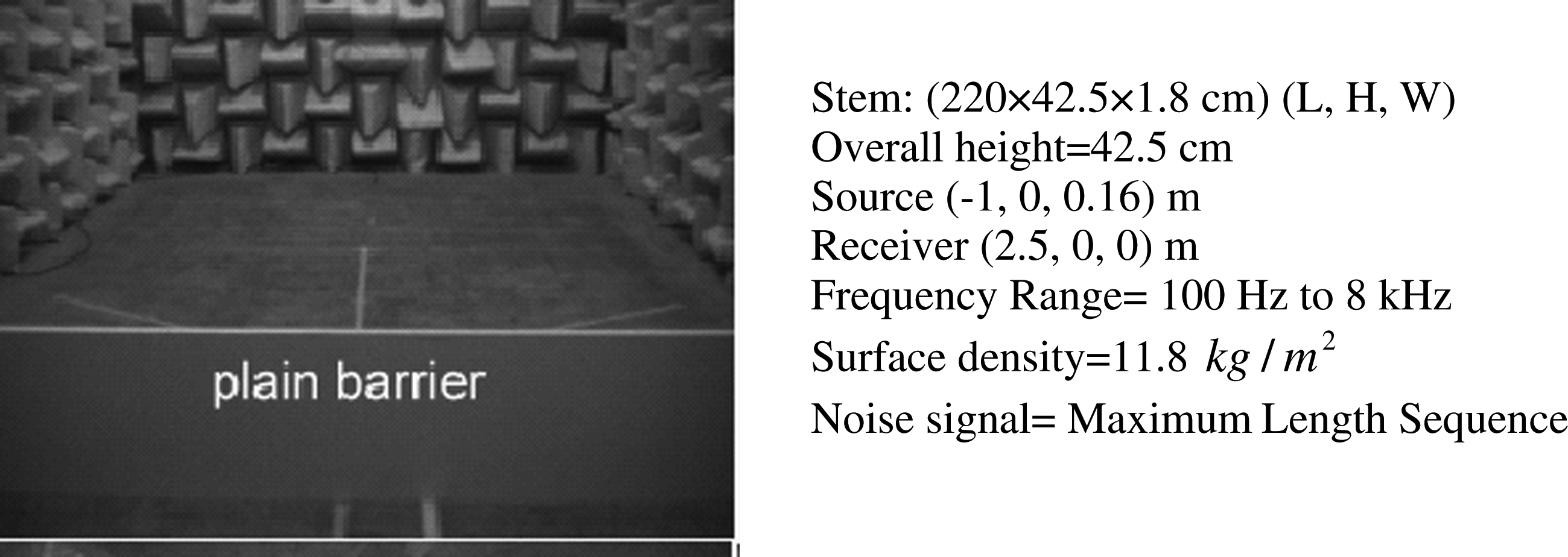
Plain barrier design in a semianechoic chamber.
To decrease the surface absorption, the entire surfaces were carefully varnished. As it can be seen from Fig. 11, there was a good agreement between measurement and prediction results.
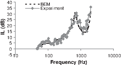
Measured and predicted spectra of a plain barrier model. BEM, boundary element method.
Conclusions
In this study, to reduce the negative effect of a plain median barrier in the presence of roadside noise barrier, different median barrier models were designed and the acoustic performance of the complex models over different receiver locations at 1/3 octave band between 50 and 4,000 Hz were predicted using an experimentally verified 2D BEM. All of the tested models were compared with their equivalent plain barrier, namely barrier model HAI, and the results were summarized as follows:
Erecting a plain median barrier as a new structure along with a 3-m roadside noise barrier has shown a reduction in the mean A-weighted insertion loss compared with a roadside barrier by 2 dB (A), which was in consistent with previous studies (Bowlby, 1984; Monazzam and Nassiri, 2009a; Watts, 1996). According to the geometry of the models and wavelength of the wave frequency, selectivity behavior due to the constructive and deconstructive effects of the incident and reflective waves could be seen. Comparing the overall results of the tested barriers (except in barrier models TAI and LAI) has shown that the negative efficiency of barrier model HAI could be decreased. The negative performance of barrier models TAI and LAI was due to their edges' design, which could result in more reflections. However, wave cancellation in some frequencies in the mentioned barriers makes the improvement. Totally, the numerical simulations in this study have shown that sloped barriers due to redirecting the wave upward were slightly better than profiled barriers. Although the boundary geometries of barrier models KAI and AAI were different, their performance in the shadow zone behind the roadside barrier was similar. This was due to their sloped surface, which was toward the opposite side of roadside barrier and thus can degrade the multiple reflections between barriers.
Finally, it should be stated that, although different designs of barriers could make some improvements relative to their equivalent plain median barrier, employing other sound-absorbing or diffuse material on these barriers can make them more effective. Further work is being carried out to study the above results, which will be the subject of future papers.
Footnotes
Acknowledgment
The authors thank the Tehran University of Medical Sciences for financial support of this study.
Author Disclosure Statement
The authors declare that they have no conflicts of interest.