
Abstract
Abstract
Formation of nitrogen oxides was investigated in the heating system of a coke oven during the combustion of enriched blast furnace gas (BFG). Due to the high temperatures in the heating system in situ measures cannot be taken. With the help of computational fluid dynamics (CFD) the combustion process can be investigated in order to predict the formation reaction of NO. For this problem a nonadiabatic simulation model composed of different models and submodels that described turbulence of flow, radiation, flame characteristics, species transport, and the formation of NO was used to calculate the thermal and prompt NO emission in a pseudo steady state. The simulation tool was applied to predetermined operating points of the coke plant. The goal of this study was to investigate the influence of a staged combustion of BFG that was enriched with natural gas, converter gas, and alternatively coke oven gas on NO emission. The NO emissions of the single-stage BFG combustion increased with rising air excess up to an O2 offgas content of ∼3%. After having passed this maximum the NO emissions decreased. Although the double-stage NO emissions show a slight increase with rising air excess, the CFD analysis demonstrated that a double-stage combustion of BFG produces lower NO emissions than a single-stage combustion.
Introduction
Eisenhut et al. (1990) investigated the influence of the average nozzle brick temperature on the formation of NO X for different heating systems. It could be demonstrated that the NO X amount is increasing with rising nozzle brick temperature. Using a staged heat supply the NO X emission reaches a lower level because of a substoichiometric combustion leading to lower flame temperatures (Stewen, 1992). Another measure to reduce the formation of nitrogen oxides is an external recirculation of combustion gases, which causes a decrease of the O2 partial pressure (Stewen, 1992). Eisenhut et al. examined the NO X concentration dependence on the ratio of recirculated combustion gases to air in the heating system. They found out that the amount of NO X decreases when the level of the recirculation ratio increased.
Hermann et al. (1992) carried out an investigation concerning the entrance angle of the combustion air and furthermore the flow patterns and the NO formation in the heating system of a coke oven. This work was done in the course of an analysis for the erection of the coking plant Kaiserstuhl III. The heating walls of this coking plant were subdivided into 36 heating flues that were arranged into twin flues with regenerator cells. The heating flues were equipped with a three-staged air supply (one stage at the bottom and two wall stages). For the tests, a twin flue model made of Plexiglas has been used. The model was operated with water. For the flow visualization dye of different color was used for air and combustion gas. The study revealed that an angle of 30° in the third air stage (second wall stage) induces a good mixing behavior between gas and combustion air. The flow field in the twin flue showed a reverse flow in the bottom region. As a consequence of this vortex an intense mixing of gas and air was introduced. Furthermore it was observed that a decrease in the formation of NO can be achieved by means of reducing the air supply at the bottom and increasing the air feed of the other stages.
Stewen (1992) and Wessipe et al. (1997) indicated the effect of internal bodies that maybe used as construction elements in coke oven heating systems. Wessipe et al. performed tests using honeycomb bodies made of refractory materials and investigated the formation of NO X in heating systems. With the use of honeycomb bodies they observed the development of a very uniform flow pattern and temperature distribution over the heating flue height. As a consequence the NO X emission decreased compared with experiments without honeycomb bodies.
In the current study CFD is used to investigate the formation of NO during the combustion of BFG in the heating system of a coking plant at the voestalpine Stahl GmbH in Linz. In the course of this investigation we analyze the impact of the combustion air and gas supply channel geometry on NO and CO emissions. In the subsequent section we specify the models and assumptions used. By means of a case study the influence of a staged BFG combustion is investigated.
Review
Heating flue geometry
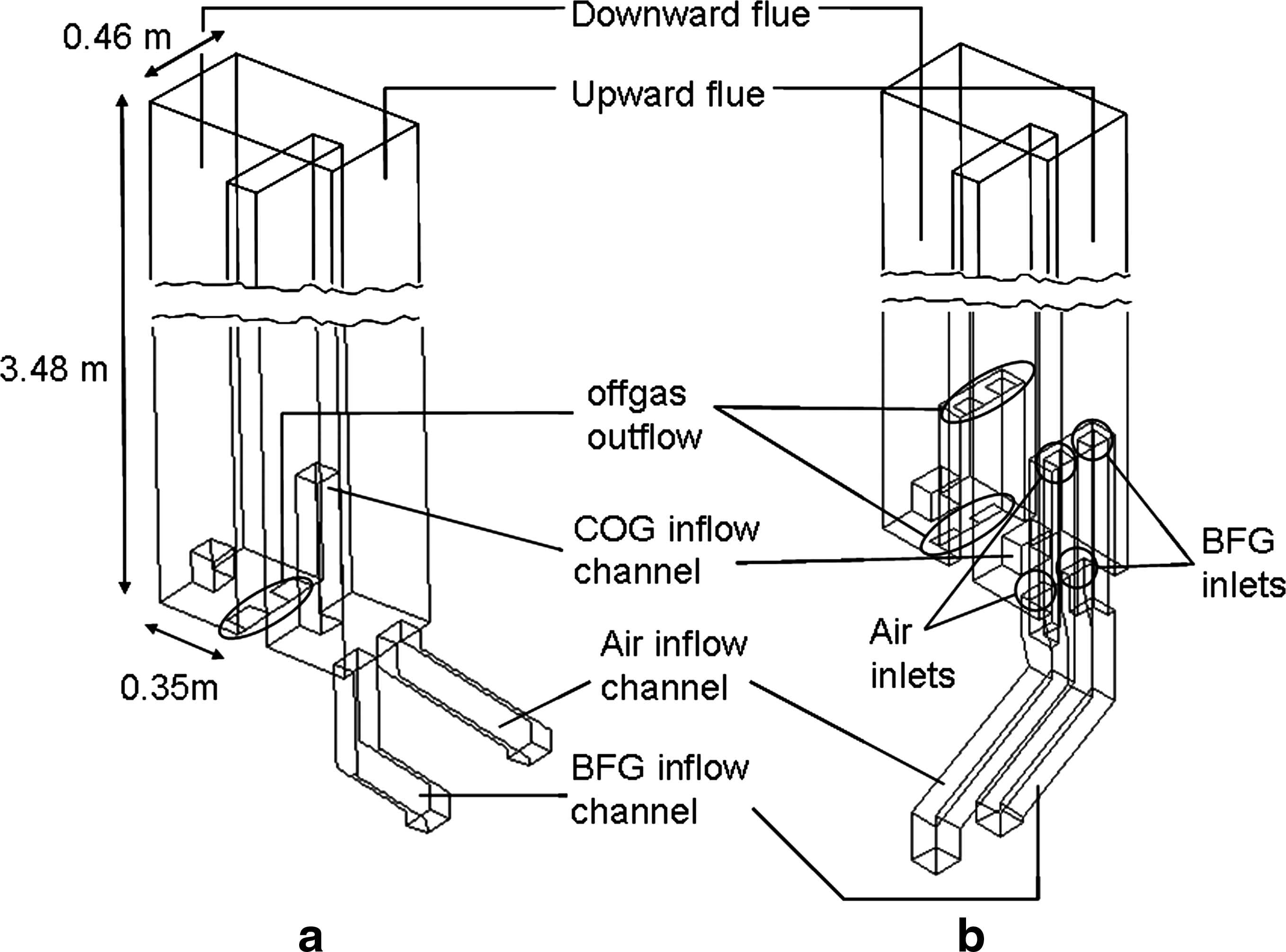
The coking plant investigated in this study consists of 5 coke oven batteries with a total of 200 coke ovens. One coke oven heating wall is subdivided into 26 heating flues whereas two single heating flues are combined to one twin flue. A heating flue has a height of 3.48 m with a length of 0.35 m and a width of 0.46 m as shown in Fig. 1.
Twin flue geometry: specification of boundaries for a single-stage feed
The coking plant in Linz contains coke oven batteries with single-stage and double-stage combustion of BFG as fuel gas that is enriched in a prior mixing station with natural gas, converter gas, and COG to obtain a certain heating value being necessary for the coking process. Alternatively pure COG can be used as feed. The gas supply channels have certain geometry. In the coking plant the heating system is situated directly above the heat exchangers, which are realized in form of regenerators. Therefore the available space for the gas supply channels feeding the heating system is extremely limited. Concerning the geometry of the supply channels for gas and combustion air there are differences between the single-stage and double-stage batteries; compare Fig. 1. The heating flues for the single-stage combustion have one vertical channel and one channel with an oblique angle of 45°. The BFG inlet channel is vertical so that the oblique air flow penetrates into the vertical BFG flow. The double-stage heating flues are equipped with two vertical gas supply channels as shown in Fig. 1b. Another difference is the length of the COG inflow channels as shown in Fig. 1a, b. The single-stage batteries contain long (0.63 m) or alternatively short (0.13 m) COG supply channels. The heating flues of the double-stage batteries possess equal COG inflow channels. The only correlation between single-stage and double-stage COG operation is that the short single-stage COG channels (cf. downward flue, Fig. 1a) and the COG channels of the double-stage system (Fig. 1b) are of the same length. Furthermore, for COG, the geometry of the gas inlet orifice of single-stage and double-stage combustion is also different. For the single-stage combustion there is a circular inlet. The COG channel for the double-stage combustion possesses an oval inlet. It can be expected that the configurations of the gas inlet channels might have an impact on the flow, the temperature distribution, and furthermore on the NO distribution. The current study considers the configuration of the single-stage and double-stage gas inlet channels for the BFG combustion.
Model setup and numerical simulation
Various aspects of the coke oven operation mode produce unsteady conditions in the heating system. Although acting on different time scales, among these effects are the periodic change of hot coke and cold coal during the coking cycle, the periodic change in flow direction according to the regenerator cycles, as well as the seasonal change of heat loss. As a simplification, in the current study, a quasi-steady representative state was assumed for the flow. The description of flow, temperature, and species concentration fields in the twin flue is based on transport equations for energy, momentum, and reaction species. For modeling of flow with the CFD software package FLUENT, the Reynolds-averaged Navier-Stokes equations are applied. In this approach the solution variables φ such as gas velocity, temperature, and species concentrations are decomposed in the form of
where
where the product term of the fluctuating components on the right hand side of Equation (2) must be described by a turbulence closure model. In the present simulations, the widely used standard k-ɛ model, which is limited to fully turbulent flows (high Reynolds numbers), is believed to be enough accurate to describe the turbulence effects in the flue.
In the coke oven heating system the nonpremixed combustion represents the basis of the reactive species transport, because the free jets of gas and air mix after having entered the heating flue. For this configuration a diffusive combustion chemistry is adequate. Under these assumptions the mean mixture fraction approach can be used (Peters, 2000). With the help of the mixture fraction f the probability density function (pdf) p(f ) can be determined as
describing the time-dependent fluid composition at a certain point where Δf is the mixture fraction's fluctuation value, T the time scale, and τ
i
is the amount of time (s) that f is spending in the Δf band. The probability distribution p(f ) is used to calculate averaged values of the scalar variables (e.g., density, composition, or temperature of the gas) storing them in nonadiabatic pdf-lookup tables with the form (Peters, 2000; Warnatz et al., 2001)
with the enthalpy H (energy/mass). Equation (3) can be extended with the steady laminar flamelet model (Peters, 2000) considering the local flame stretching resulting from a turbulent dissipation of energy. This model is restricted to the nonpremixed approach considering only a single mixture fraction system and can be expressed in the form
where χst is the scalar dissipation (degree of flamelet extension) (s−1) at the position of the stoichiometric mixture fraction fstoich. The surface of the stoichiometric mixture fstoich defines the flame surface.
Radiation
Radiative heat transfer in heating flues is of central importance since the heat released within the flame is mainly transported by radiation to the walls adjacent to coke chambers. Therefore a nonadiabatic approach has been chosen. Due to considering radiation effects the energy transport equation is solved. The resulting heat flux through the wall directed toward the coke side was prescribed in our model as a boundary condition of the form
Reaction mechanism
For description of the combustion kinetics a 41-reaction mechanism for methane combustion was used (Correa, 1993). In this mechanism the following 16 species are involved in the combustion of BFG: N2, O2, CH4, H2, CO, CO2, H2O, OH, H, O, CH3, HCO, HO2, H2O2, CH2O, and CH3O.
Within this list the seven leading species (at the beginning of the list) represent macro components, which are addressed in the form of boundary conditions into the flow domain specifying the feed composition. All other species are considered as combustion intermediates.
NO model
The formation of NO consists of a thermal and a prompt NO fraction and can be described by standard FLUENT models. Fuel NO as third-known formation mechanism is not of importance for the present calculations due to the elementary composition of the fuel.
The formation rate of the thermal NO fraction can be written in a simplified form (Warnatz et al., 2001)
where k is the rate constant for the formation reaction. The simplification of Equation (6) originates from the short lifetime N radicals (being quasi-instantaneously consumed in series reactions) that are essential in the thermal NO mechanism. As a consequence their concentration is assumed being quasi-steady and therefore neglected in the overall rate law from Equation (6). The prompt NO formation rate is defined as
where a is the O2 reaction order. The square brackets in Equations (6) and (7) denote the species concentration in mol/m3. The term [FUEL] in Equation (7) denotes the total fuel concentration in mol/m3.
For the thermal NO calculation the O radical and the OH radical as well are important. Concerning the prompt NO emission CO and CH4 are the most important fuel components. All these species have to be determined as macro and intermediate species concentrations and originate from the previously mentioned 41 combustion mechanism.
Boundary conditions
Apart from two walls joining adjacent coke chambers the walls of the heating flue are assumed to have a constant temperature of Twall=1,300°C that equals the measured nozzle brick temperature. For the two walls joining adjacent coke chambers it is assumed that there is a thermal wall flux into the coke chamber as a result of thermal conduction. The temperature of these two radiative walls is Trw=850°C. The wall emission factor is set to 0.8 (adequate for refractory materials). The inlets of combustion gas and air are defined as velocity inlets. The inlet gas velocity is calculated from the cross-sectional area and the volumetric flow rate.
Programming
The numerical calculations have been done with the CFD package FLUENT 6.3. The three-dimensional model of the heating flue has been created with the software GAMBIT and consists of 75,557 hexahedral cells. This model represents the control volume for the FLUENT simulation runs and has a nearly Cartesian grid structure with nonequal cell spacing. The typical cell size in the inlet near mixing layer region is ∼22 mm whereas further downstream in the downward-directed duct the typical cell size is ∼49 mm. In the simulation runs the first-order upwind scheme was used for the conservation equations of energy, momentum, k, ɛ, f, and pollution NO. Standard FLUENT convergence criteria have been used. Stationary fields of flow, turbulence, energy, and species were calculated simultaneously. In prior trial runs the NO concentration field was determined as a postprocessing step following the solution of the flow and the combustion model. The results of these runs were then compared with results of simultaneous calculation runs. There were no noteworthy differences; however, the advantage of simultaneous calculation runs turned out to be a remarkable saving of running time. The CFD calculations of the BFG combustion converged after about 400 iterative steps. Furthermore it was investigated whether a higher grid resolution influences the simulation results. For some simulation trial runs a grid resolution that was twice as high as the previously described resolution has been applied. Moreover a second-order upwind scheme was used for the conservation equations. No appreciable differences in the temperature distribution and the NO emissions have been found compared with the cases with lower resolution and first-order discretization schemata. The higher cell resolution and the second-order discretization are more CPU processor capacity–intensive and lead to higher calculation times.
In addition to the simulation runs the accuracy of the FLUENT-calculated combustion heat fluxes has been checked with the help of a MATLAB routine. The heat release as calculated by this heat balance model represents the enthalpy difference between the offgas and the inflow gases (combustion gas and air). An ideal, complete combustion was assumed. The adiabatic flame temperature was estimated from the heat balance model. Results showed that the heat releases calculated by the MATLAB stand-alone routine are marginally higher than the FLUENT heat releases, because the MATLAB model assumed an ideal gas mixing and prompt starting of combustion reaction, without combustion intermediates partially remaining in the offgas. Our model calculations show the convective heat flux to be in the order of 2% of the radiative wall heat flux and therefore to be of minor importance.
Case Study
To illustrate the simulation results of the BFG combustion one operating point represents the base case. The results of the single-stage and double-stage combustion simulations are compared with this base case. Tables 1 and 2 illustrate the composition and the flow rates of the combustion gases. The combustion air consists of 20.69 vol.% O2, 77.82 vol.% N2, and 1.49 vol.% H2O. The BFG case study shows the influence of the air excess concerning the NO emission during the BFG combustion. Concerning the NO emission, in all BFG cases single-stage combustion is compared with double-stage combustion.
BFG, blast furnace gas.
FG, fuel gas.
Discussion of Numerical Simulation Results
In the current study the formation of NO in single-stage and double-stage combustion of BFG is compared. Additionally the amount of combustion air is varied by keeping the volumetric flux and the inlet temperature of BFG constant and increasing the air flux stepwise starting from the base case operating point. Figure 2 shows the velocity distribution of the BFG base case for a single-stage and a double-stage combustion. Due to the smaller cross-sectional area of the gas inlets the single-stage combustion produces higher peak velocities within the free stream jets entering the flue. Furthermore, in the single-stage combustion the air flow streams into the twin flue with an oblique angle, Fig. 2a. In this case stronger velocity gradients result and gas mixing is enhanced near the entrance region. Figure 3 illustrates the velocity pathlines of BFG and air. For the single-stage and double-stage combustion a backflow area exists in the upstream flue enforcing the mixing of BFG and air. Due to the higher velocities during single-stage operation the combustion reaction starts near the BFG entry and the highest peak temperatures are found in the BFG entry zone. Contrary, the double-stage combustion in Fig. 4b produces a nearly symmetric temperature distribution, due to the injection of BFG and air being directed vertically and parallel.
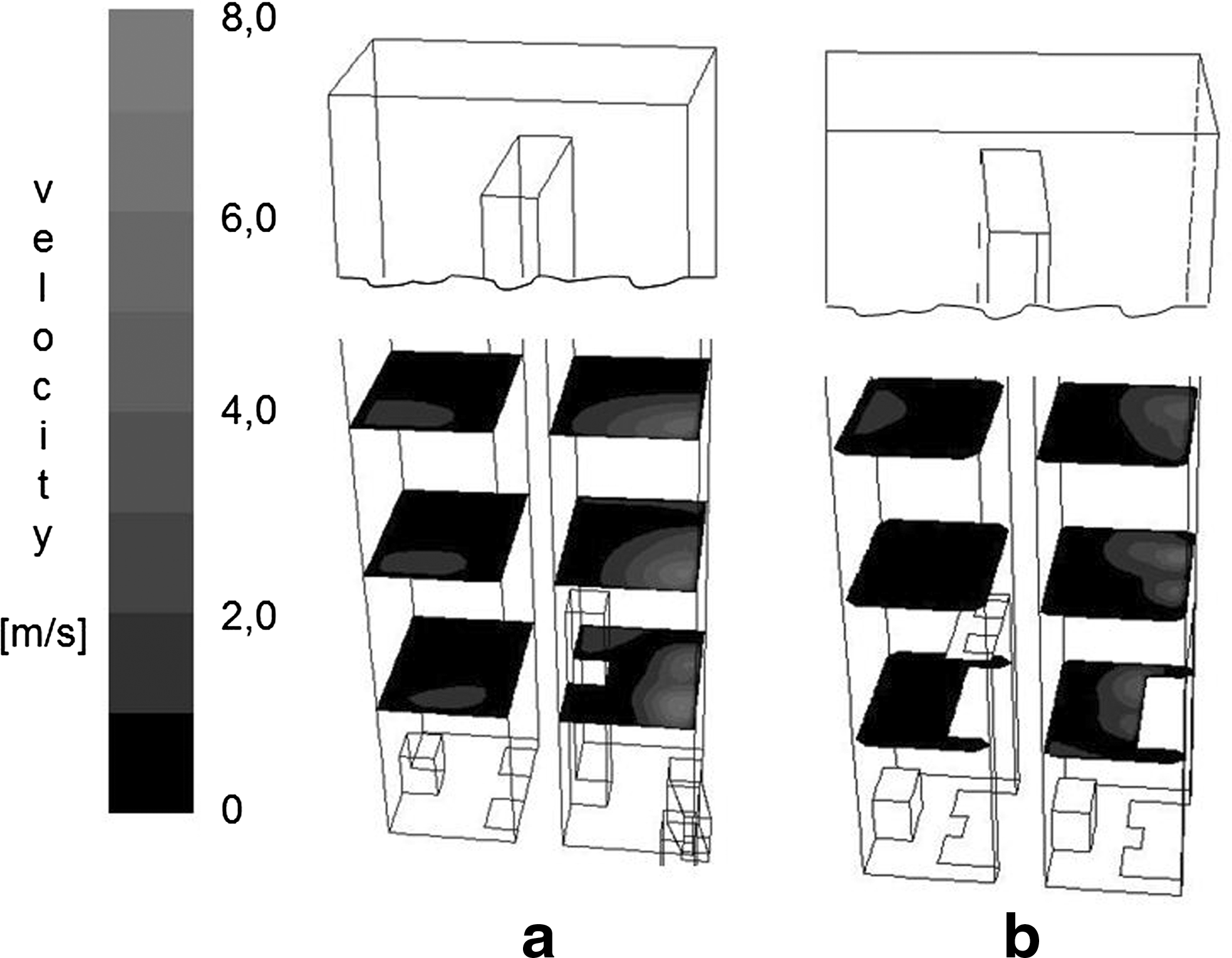
Simulated distribution of the absolute velocity for the BFG base case:
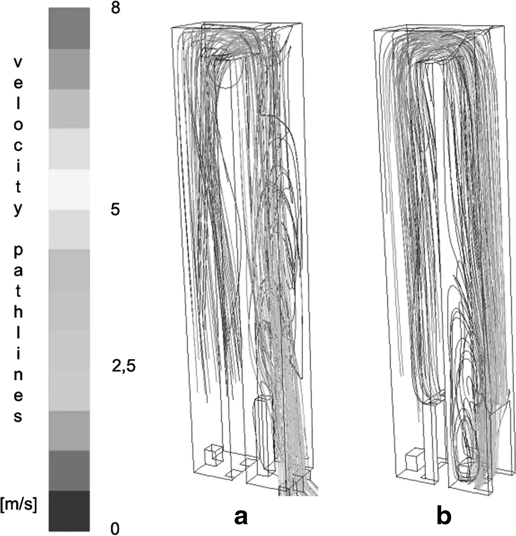
Simulated velocity pathlines for the BFG base case:
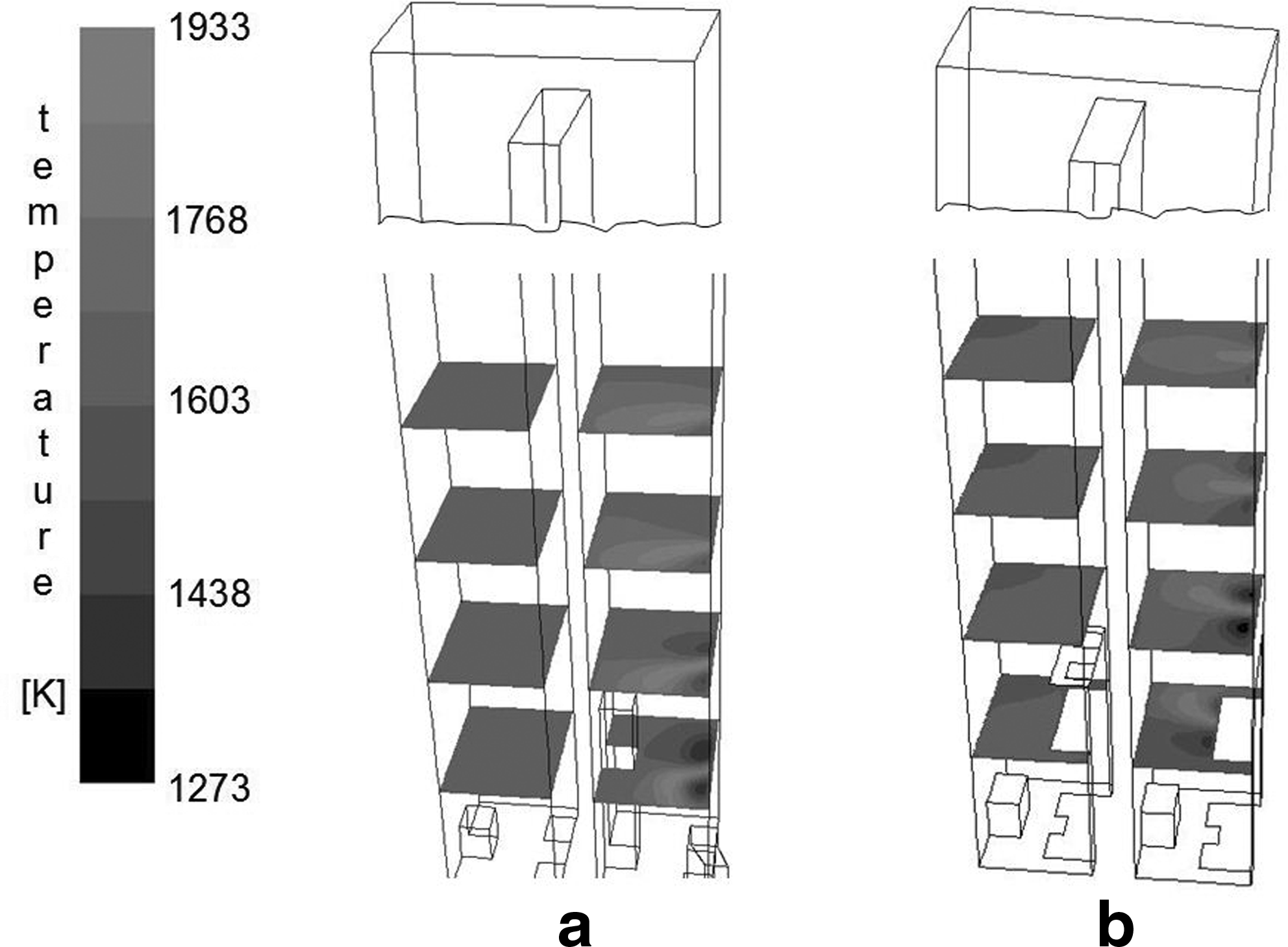
Simulated temperature distribution for the BFG base case:
Figure 5 shows the trends of the single- and double-stage NO concentration during BFG combustion in dependence of the air excess ratio λ. The NO emissions at 5% reference O2 are given in mg/m3STP,dry. For the single-stage base case with an air excess ratio of 0.9 an NO emission of 470.0 mg/m3STP,dry was calculated. The NO concentration emitted from the double-stage base case is lower with 350.8 mg/m3STP,dry and stays below the single-stage NO emissions for the entire range of air excess investigated. These findings are in accordance with the well-known potentials for NO reduction that can be introduced by fuel and air staging. When raising the air excess ratio from λ=0.9 to 1.0 the single-stage combustion leads to an NO emission that is about 27.6% higher compared with the base case whereas the NO emission of the double-stage combustion is only increased by 17.4%. Regarding the percentage of the NO concentration change, the results indicate that for the double-stage combustion an increasing of the air excess leads to a minor growth in the NO emission.
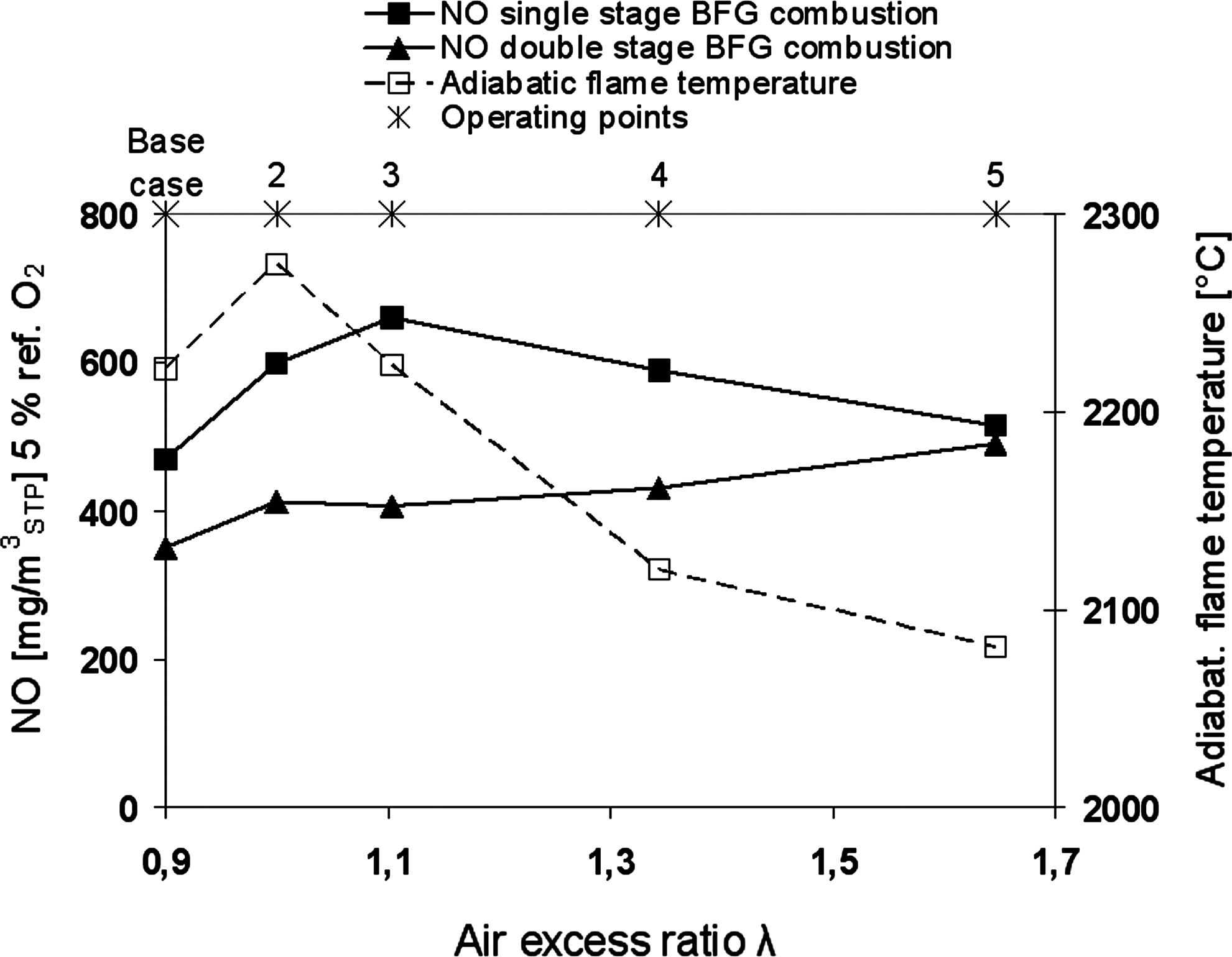
Simulated NO emission and adiabatic flame temperature for single-stage and double-stage BFG combustion depending on the air excess ratio.
For single-stage BFG combustion within 0.9<λ<1.0 the increasing adiabatic flame temperature causes an enhancement of thermal NO. Since thermal NO formation is a function of excess air and temperature in the combustion zone, NO emission runs through a maximum with increasing λ, which however turns out to be slightly offset from the peak temperature at λ=1.0. A maximum of NO emission is found at an air excess of λ=1.1. Therefore, in single-stage combustion starting at stoichiometric conditions the NO emission increases with rising O2 amount up to an O2 offgas content of ∼3 vol.%. Within the range 0.9<λ<1.1 the kinetics of NO formation according to Equations (6) and (7) are enhanced due to increasing concentrations of N2 and O2 entering the combustion zone. For combustion conditions with λ>1.1 the further reduction of the adiabatic flame temperature due to a dilution effect by the air excess leads to a decrease of the thermal NO. Contrary, for the double-stage combustion a rising O2 offgas content correlates with a slightly but monotonically increasing NO emission. In this case it turns out that the surplus of O2 and N2 in the upper stage provided by air staging is not in contact with the flame's peak temperature zone (cf. Figs. 4 and 6). Comparing these figures the temperature and O2 maxima can be seen not to overlap sufficiently. As a consequence the double-stage NO emission is reduced and CO exit concentration remains higher than in the single-stage case. The simulation runs estimated the share of thermal NO in total NO emissions with ∼85%. The remaining 15% are prompt NO.
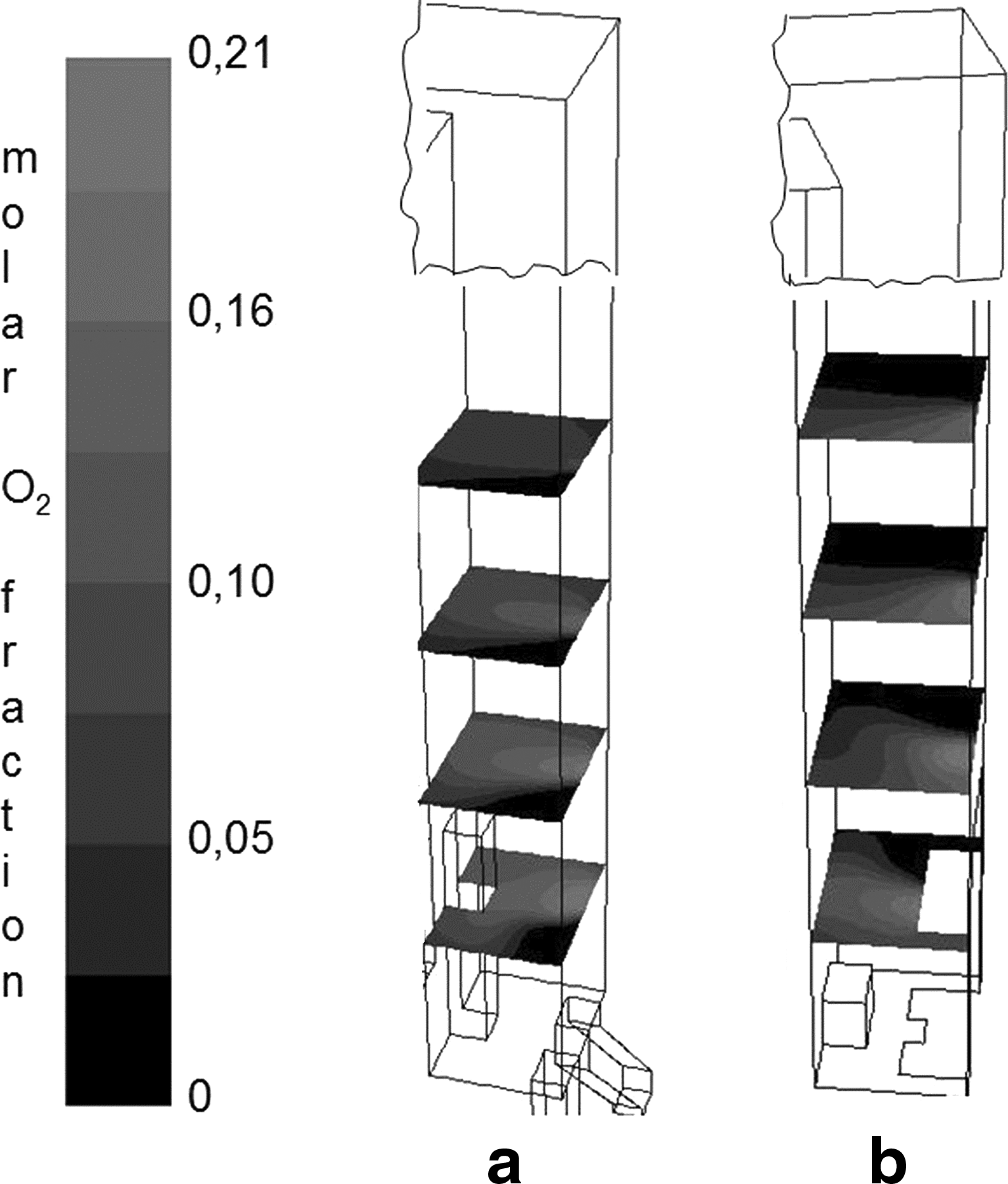
Simulated molar fraction of O2 of the BFG case in the upstream flue:
The calculated BFG cases demonstrate the NO and CO emissions to show contrary characteristics in their dependence on the air excess as can be seen from Figs. 5 and 7. For an air excess ratio λ<1.0 CO cannot be oxidized due to the O2 deficit. With rising air excess the oxidation reaction starts and the CO emissions decrease. For λ>1.2 there is a slight increase of the single-stage CO emissions due to the growing deficit of OH radicals that are necessary for the CO oxidation, following the main reaction route CO+OH→CO2+H. Furthermore the absolute values of the single-stage CO emissions are lower than the double-stage CO emissions. At the reduced flame temperature of the double-stage combustion the CO oxidation can no longer proceed with the same reaction rate than during the single-stage combustion and therefore results in higher CO emissions. As shown in Fig. 6, double-stage operating points possess higher O2 offgas contents compared with single-stage operation, which is a consequence of the bypass effect occasionally introduced in the staged combustion configuration as already discussed previously.
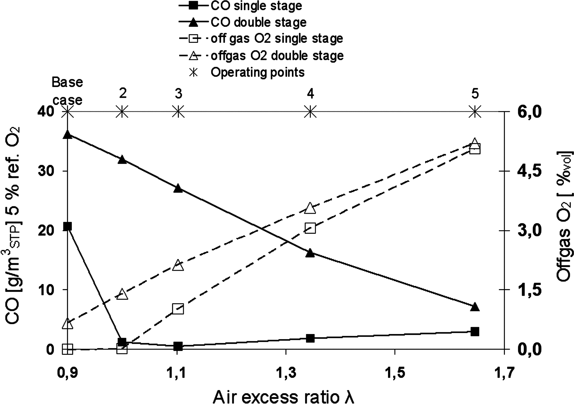
Simulated CO emission and offgas O2 content for single-stage and double-stage BFG combustion as a function of the air excess ratio.
Figures 8 and 9 have been chosen from a large amount of coke plant–operating data comparing simulated NO and CO emissions as a function of offgas O2 against battery averaged measured data during double-stage (Fig. 8) and single-stage (Fig. 9) BFG combustion. The operational range of the coking plant is limited to off gas O2 level between 3% and 3.7% for single-stage operation and 2.5% up to 5.3% for double-stage operation with some exceptional periods reaching an offgas O2 level of ∼8%. In the calculations an interval from 0% to 7% offgas O2 has been investigated.
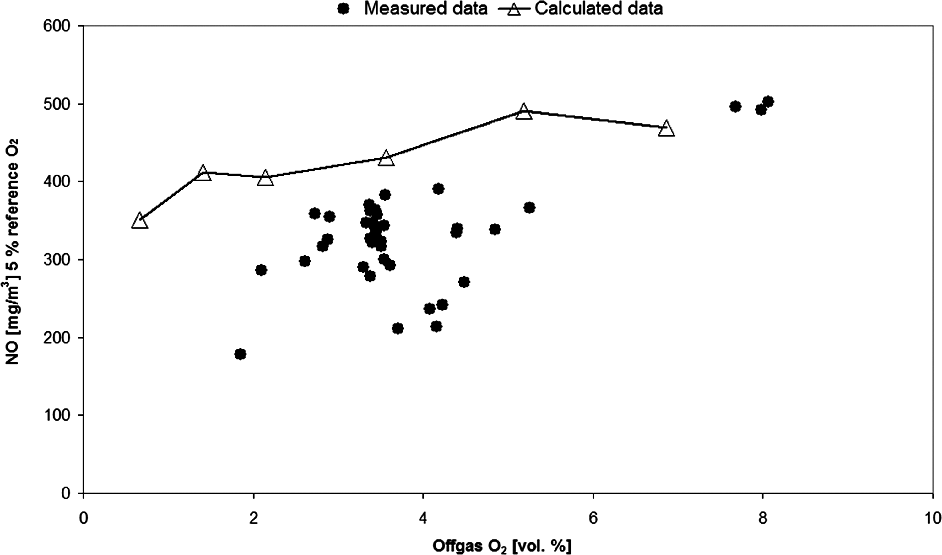
Measured and simulated NO emission for double-stage BFG combustion as a function of the offgas O2 content.
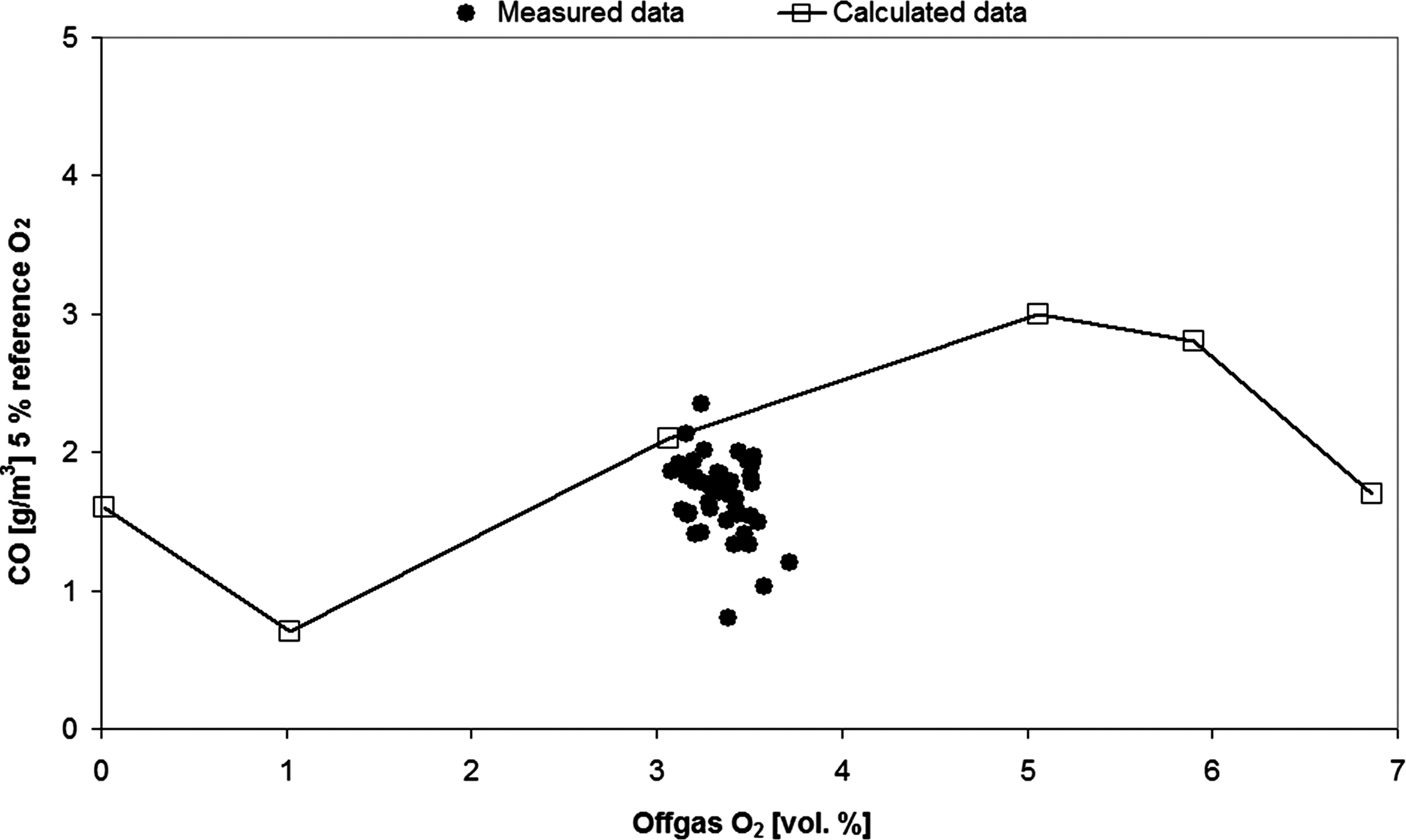
Measured and simulated CO emission for single-stage BFG combustion as a function of the offgas O2 content.
Figure 8 compares calculated and measured NO emission values of double-stage combustion. The numerical data show an order of magnitude correspondence forming an upper envelope compared with the measured data. In this context it is important to keep in mind that the simulation is based on a quasi-steady approximation of the regenerative heating system.
Figure 9 shows the simulated and measured CO data during single-stage BFG combustion. Due to the restricted operational range measured CO emissions could be obtained only in a small offgas O2 range showing a very good compliance to the simulated CO emissions. The simulated CO emissions generally overpredict the measured data. We believe that this behavior may be due to the formation of condensed forms of carbon species (PAH) as precursors of soot. For the present CFD runs we did not include a soot formation model. The measured NO and CO emissions of the other coke batteries show similar trends to the presented data.
Conclusions
In the current study the combustion of BFG in the heating system of a coke oven at the voestalpine Stahl GmbH in Linz is investigated. To determine the flow field, the temperature distribution as well as the NO and CO emission CFD is used. This numerical simulations are done with the help of the CFD package FLUENT and are targeted on the comparison between a single-stage and a double-stage combustion. The combustion kinetics are modeled with the standard FLUENT models of a nonpremixed combustion method using a nonadiabatic steady laminar flamelet model. In the calculations the influence of the air excess during the BFG combustion is investigated concerning the formation reactions of NO. The basic intention of the simulations is to explore mechanisms causing the NO emissions during changing operating conditions in the coke plant.
The BFG simulations showed that the air excess has an influence on the formation of NO. The simulations confirm the generally known fact that the double-stage combustion produces lower NO emissions than the single-stage combustion. At the double-stage combustion there are lower peak values for the temperature and NO compared with the single-stage combustion. In addition to the air excess the geometry of the gas supply channels has also an influence on the formation of NO. Because of the vertical injection direction of BFG and combustion air the double-stage combustion generates a much more uniform flow field and temperature distribution compared with the single-stage BFG combustion. This homogeneity of the flow field leads to lower NO emissions during the double-stage combustion.
Considering the full nonstationary combustion during the regenerator cycle as well as the incorporation of a soot submodel for a further advanced CFD tool remain an open challenge for future studies that might help to reduce still existing deficits in the emission load prediction.
Footnotes
Acknowledgment
This work has been financially supported within the Austrian Competence Center program COMET.
Author Disclosure Statement
No competing financial interests exist.