
Abstract
Abstract
Urea-selective catalytic reduction (SCR) has been reported as the most promising technique for adherence to NOX emissions regulations. In the urea-SCR process, NH3 is generated by urea thermal decomposition and hydrolysis and is then used as a reductant of NOX in the SCR catalyst. Therefore, improving the NOX conversion efficiency of urea-SCR requires enhancement of thermal decomposition upstream of the SCR catalyst. In the present work, two types of mixing chambers were designed and fabricated to improve urea thermal decomposition, and experiments with and without a mixing chamber were carried out to analyze thermal-decomposition characteristics of urea in the exhaust pipe with respect to inlet velocity (4–12 m/s) and temperature (350°C–500°C). Urea thermal decomposition is greatly enhanced at higher gas temperatures. At an inlet velocity of 6 m/s in the A-type mixing chamber, NH3 concentrations generated along the exhaust pipe were about 171% and 157% greater than those without the mixing chamber for inlet temperatures of 400°C and 500°C, respectively. In the case of the B-type mixing chamber, NH3 concentrations generated at inlet temperatures of 400°C and 500°C were about 147% and 179% greater than those without the mixing chamber, respectively. Note that the implementation of mixing chambers significantly enhanced conversion of urea to NH3 because it increased the residence time of urea in the exhaust pipe and improved mixing between urea and exhaust gas.
Introduction
SCR systems can be roughly classified into two categories: NH3-SCR and urea-SCR. NH3-SCR using NH3 as a reductant gas effectively controls the injection rate of NH3 for NOX reduction in exhaust gases. Many previous studies have shown that it has ideal performance in NOX conversion efficiency compared with that of urea-SCR. Sullivan and Doherty (2005) showed that NOX conversion with the H2O-urea-SCR is lower than that of the H2O-NH3-SCR using Cu-Al2O3 and Cu-TiO2 SCR catalysts. Koebel and Strutz (2003) presented that the NOX conversion of the NH3-SCR is better than that of the urea-SCR. However, the SCR system using NH3 as reductant is vunsuitable for use in automotive or stationary plants due to difficulties in storing and handling of NH3. Therefore, urea is an alternative because it is not toxic and can be easily transported; hence, the urea-SCR for NOX removal from diesel exhausts has been researched by many previous studies (Koebel et al., 2000; Sluder et al., 2005; Shimizu and Satsuma, 2007). Koebel and Strutz (2003) suggested systems for thermolysis of urea with heat input by a direct heat-exchange surface and for thermohydrolysis of urea with heat input from a partial stream of exhaust gas to increase the thermolysis and hydrolysis of urea. They showed that the most promising approach is the use of an external monolithic hydrolyzing catalyst heated by a partial stream of exhaust. Nishioka et al. (2008) demonstrated a urea-dosing device with an active-NH3 production function, which can be achieved by an electrically heated bypass passage with a hydrolysis catalyst.
As illustrated in Figure 1, when the urea–water solution is sprayed into the main exhaust gas stream passing through the exhaust pipe, the water evaporates from the urea–water solution, as shown in reaction (1). The urea melts at 406 K (Koebel et al., 2000), and the thermal decomposition of urea into NH3 and HNCO begins. Urea is then thermally decomposed into NH3 and HNCO. The HNCO formed via reaction (2) hydrolyzes on the surface of the hydrolysis catalyst, producing NH3 and CO2, as shown in reaction (3). In the urea-SCR process, the NH3 generated by urea thermolysis and hydrolysis is finally used as a reductant of NOX in the SCR catalyst. NH3 is essentially required to enhance the thermal decomposition upstream of the SCR catalyst to improve the NOX removal (Koebel and Strutz, 2003).
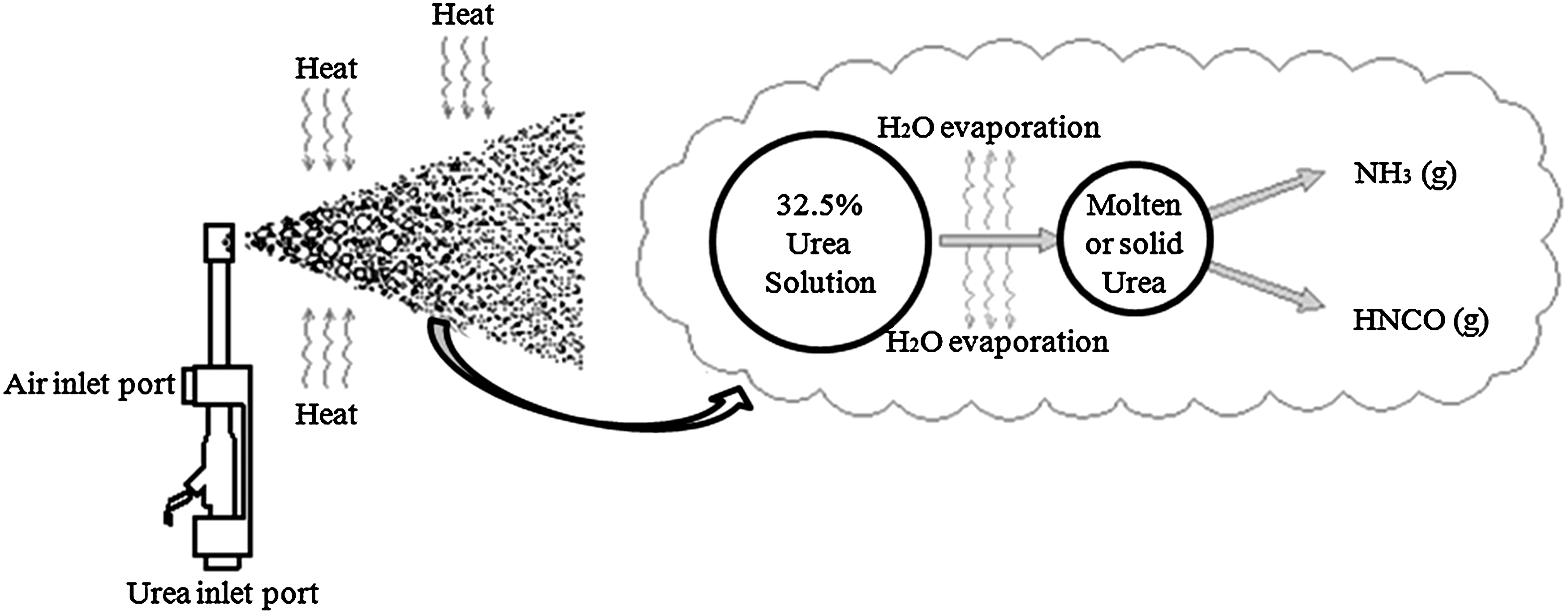
Schematic of the thermal decomposition mechanism of urea–water solution.
Many previous studies highlight that the urea injection rate, the residence time of urea in the exhaust pipe (i.e., exhaust gas velocity), and the exhaust gas temperature are crucial factors for the thermal decomposition of urea. If the residence time is not sufficiently long, then, residual solid urea can be deposited on to the catalyst surface, which may have adverse effects on the deNOX performance. Also, if an inadequate quantity of urea–water solution is injected, a NH3 slip or a low NOX removal through the SCR catalyst can be incurred by an excessive and insufficient injection of urea, respectively, and these are especially severe at lower temperatures (Koebel and Strutz, 2003; Eichelbaum et al., 2010).
In this article, the characteristics of urea thermal decomposition in the exhaust pipe are experimentally examined for the following parameters, namely; (i) the residence time, that is, inlet gas velocities in the range of 4–12 m/s, (ii) the inlet gas temperature in the range of 350°C–500°C), and (iii) two types of mixing chambers designed and fabricated to improve the urea thermolysis. Meanwhile, the limitation of performance improvement in the passive system with mixing chambers without an implementation of external heat source and hydrolysis catalyst can be observed. The thermal decomposition characteristics of urea to HNCO and NH3 without a mixing chamber are experimentally examined and compared to those with mixing chambers.
Experimental Setup
Figure 2 shows the experimental apparatus used in the present work, consisting of three main parts: a gas burner and blower, a urea injection module, and a Fourier transform spectroscopy (FT-IR) gas analyzer.

Schematic of the experimental set up. 1, LPG gas; 2, blower; 3, gas pressure regulator; 4, gas pressure gage; 5, solenoid valve; 6, gas flow control pilot valve; 7, ignition device; 8, pilot burner; 9, air flow control pilot valve; 10, air flow control valve; 11, flame detector; 12, burner; 13, compressor; 14, pressure vessel; 15, injector controller; 16, urea dosing module; 17, mixing chamber; 18, exhaust pipe; 19, gas sampling line; 20, gas sampling port; 21, thermocouple; 22, temperature indicator; 23, urea pressure regulator; 24, air pressure regulator; 24, FT-IR gas analyzer.
The gas burner and blower comprises a gas pressure regulator, a solenoid valve, the gas and air flow control pilot valves, an ignition device, a pilot burner, a flame detector, and a burner. These are used to generate and maintain the inlet velocity and temperature conditions that range from 4 to 12 m/s, which is similar to the typical operating conditions of a diesel engine, and at temperatures from 350°C to 500°C. Each set of inlet velocity and temperature is kept constant by a feedback control system.
The urea injection module consists of an air compressor, a pressure vessel, a controller, and an injector. The pressure vessel filled with urea–water solution is kept at a constant pressure of 2 bar using the air compressor, and its maximum allowable working pressure is 10 bar. The pressurized urea–water solution is supplied into the inlet port of the injector and is then mixed with compressed air at 1.8 bar in the mixing chamber of the injector. Well-mixed urea and air are then injected into the exhaust stream through the four-hole nozzle. The injection rate of urea is controlled by adjusting the frequency and duty ratio in the controller. The injector and controller operate on 12 V DC power. A specified amount of 2.6×10⁻⁵ kg/s urea–water solution (32.5 wt% urea) is continuously fed into the exhaust pipe using an air-assist type injection module. The exhaust pipe connected to the gas burner and blower is well insulated. Sauter mean diameter (SMD) characterization tests at the 5% duty ratio and 10 Hz frequency with three- and five-hole vertical-type nozzles were used in the urea-dosing module. Measurement point of SMD characterization is 250 mm away from the urea injection. Table 1 shows the number-based distribution of the SMD characterization test results. (Han and Park, 2008).
Measurement point of SMD characterization is 250 mm away from urea injection.
The number-based distribution.
SMD, Sauter mean diameter.
Gas sampling is carried out from five sampling ports located at 1 m intervals from the urea injection.
Gas temperature is measured at the center of an exhaust pipe using the K-type thermocouple. The gas sampling line and thermocouple locations are described in detail in Figure 2. The two types of mixing chambers are mounted in the exhaust stream 1.3 m from the injection. The NH3 concentration is measured using a FT-IR gas analyzer (AVL SESAM4 FTIR-218). The temperature of the FTIR-measuring cell is kept at 185°C and the measurement uncertainty of the FT-IR gas analyzer is 0.13%. Ultra-high purity nitrogen gas is used as a purge and protective gas. For a better reproducibility and reducing error, each experiment was performed three times.
Mixing chamber
Figure 3 shows the two types of mixing chambers used in the present work. The A-type and B-type mixing chambers are designed to improve the thermal decomposition of urea by increasing the residence time and the mixing of urea with the exhaust gas. The A-type mixing chamber consists of three plates with punching holes on the plate cross-section, and the plates are installed at equal intervals along the flow direction. Some of the exhaust gas bypasses through the punching holes, while the rest form the vortex flow. The B-type mixing chamber consists of a cylindrical pipe with punching holes on the periphery, one closed end, and a plate with punching holes. The diameter of the cylindrical pipe is equal to that of the main exhaust pipe, which is smaller than that of the mixing chamber (160 mm). The exhaust gas flows into the cylindrical pipe and then flows radially out through the peripheral holes of the cylindrical pipe. The diameter of the punching hole is 2 mm, and the space between the holes is 4 mm.

Schematic of the mixing chambers used in the experiment:
By implementing the mixing chamber designed in the present work, the residence time has been increased due to the following factors: (i) the mixing chamber has larger volume than the default exhaust pipe, (ii) mixing itself increases the residence time, also mixing increases heat transfer between exhaust gas and aerosols, and (iii) aerosols impact on the plate with a punching hole and then spatter to smaller droplets or form a thin film, which increase the residence time and improve the heat transfer. Unlike a monolithic catalyst, the mixing chamber adopted in this study consists of very thin plates with an aperture ratio of 50%, so the pressure drop is negligibly small.
Results and Discussion
Effects of inlet gas velocity and temperature on urea thermolysis without a mixing chamber
Without the mixing chamber, the characteristics of urea thermolysis are analyzed by measuring the NH3 concentration along the exhaust pipe at inlet velocities in the range of 4–12 m/s and inlet gas temperatures in the range of 350°C–500°C.
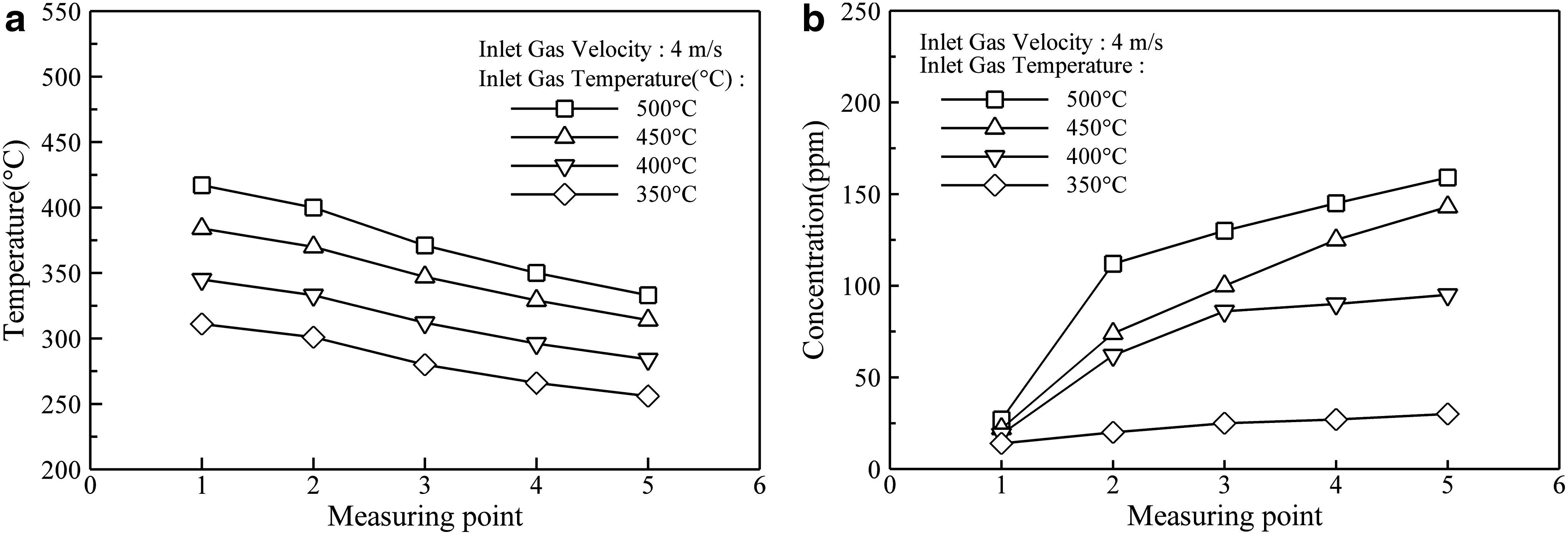
Figure 4 shows the NH3 concentration distribution along the axial distance as a function of the inlet gas temperature at the inlet gas velocity of 4 m/s. The NH3 concentration increases as the inlet gas temperature and the axial distance increase. The maximum NH3 concentration is about 159 ppm at the fifth measurement point with the inlet gas temperature of 500°C. The highest increasing rate of NH3 concentration (defined as the ratio of the increment in NH3 concentration to the increment in length) is about 85 ppm/m between the first and second measurement points. The increasing rate of NH3 concentration decreases as the distance increases. This is probably due to several factors that include: monotonic decrease in the exhaust gas temperature caused by the vaporization of urea–water solution and convective heat loss to the surrounding air, slow evaporation and thermolysis of large droplets, and decrease in the amount of unreacted urea.
Gas temperature
Upon increasing distance at the inlet temperature of 500°C, the increasing rate decreases due to a monotonic decrease in the exhaust gas temperature by the vaporization of urea–water solution and a convection heat loss to the surrounding air. This tendency exists similarly at all inlet gas temperature conditions. Regardless of the measurement point, the NH3 concentration increases with increasing inlet gas temperature. When the inlet gas temperature increases from 350°C to 400°C, the increasing rate of NH3 concentration (the ratio of the increment in NH3 concentration to the increment in inlet gas temperature) is about 1.3 ppm/°C at the fifth measurement point, and it decreases as the inlet gas temperature increases. However, at lower inlet gas temperatures below 350°C, the NH3 concentration produced is very low due to the diminished thermal decomposition (Sluder et al., 2005). There was no urea deposit found inside the pipe, with and without the mixing chamber.
Figure 5 shows the NH3 concentration distributions along the pipe for various inlet gas temperatures at an inlet gas velocity of 6 m/s. The maximum NH3 concentration is about 145 ppm at the fifth measurement point at the inlet gas temperature of 500°C. The highest increasing rate of NH3 concentration is about 75 ppm/m through the first and second measurement points. When the inlet gas temperature increases from 350°C to 400°C, the increasing rate of NH3 concentration is about 1.12 ppm/°C at the fifth measurement point.

Gas temperature
As shown in Figure 6, at the inlet gas velocity of 8 m/s the maximum NH3 concentration is about 150 ppm at the fifth measuring point with the inlet gas temperature of 500°C. The maximum increasing rate of the NH3 concentration is about 59 ppm/m between the first and second measurement points at the inlet gas temperature of 500°C, and the increasing rate decreases as the length increases. As the inlet gas temperature increases from 350°C to 400°C, the maximum increasing rate of the NH3 concentration is about 1.06 ppm/°C at the fifth measurement point.

Gas temperature
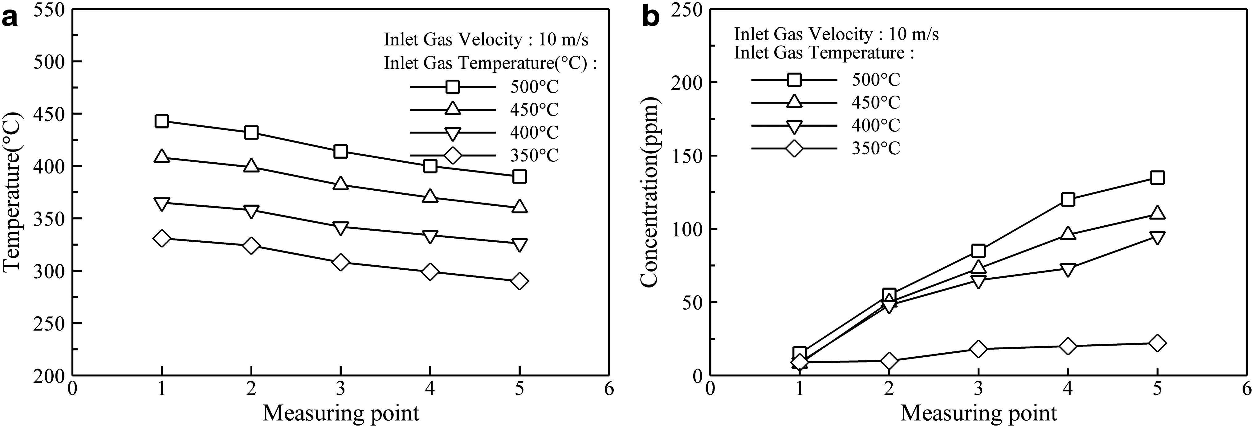
Figure 7 shows the characteristics of urea thermal decomposition for increasing inlet gas temperature and distance at an inlet gas velocity of 10 m/s. The maximum NH3 concentration is about 135 ppm at the fifth measurement point for the inlet gas temperature of 500°C. The maximum increasing rate of the NH3 concentration is about 40 ppm/m between the first and second measurement points at the inlet gas temperature of 500°C. When increasing the inlet gas temperature from 350°C to 400°C, the highest increasing rate of NH3 concentration is about 1.46 ppm/°C at the fifth measurement point. When the inlet gas velocity is 12 m/s, however, the NH3 concentration is very small (<50 ppm) regardless of the inlet gas temperature and measurement point because of the shortened residence time of urea in the exhaust pipe.
Gas temperature
Effects of inlet gas velocity and temperature on urea thermolysis with the A-type mixing chamber
To increase the residence time of urea in the exhaust pipe and the mixing of urea with the exhaust gas, the A-type mixing chamber shown in Figure 3 is implemented between the first and second measurement points. The NH3 concentration produced from urea thermal decomposition is measured along the axial distance for inlet gas velocities of 6 and 8 m/s and temperatures of 400°C and 500°C.
Figure 8 shows the NH3 concentrations along the axial distance with and without the A-type mixing chamber as a function of the inlet gas temperature at the inlet gas velocity of 6 m/s. When the inlet gas temperatures are 400°C and 500°C, the average NH3 concentrations over all measuring points are about 170% and 157% higher with the mixing chamber than those without the mixing chamber, respectively. For inlet gas temperatures of 400°C and 500°C, the NH3 concentrations at the fifth measurement point are 160 and 228 ppm, respectively, and are about 193% and 157% higher than those without the mixing chamber.
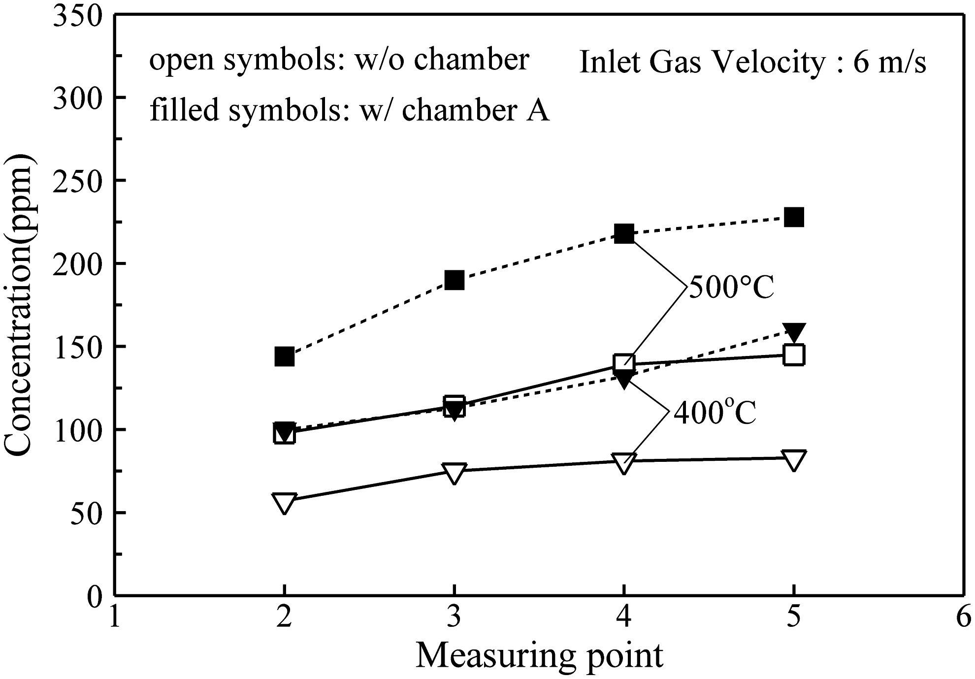
NH3 concentration profiles along the pipe with respect to the inlet gas temperature at a fixed inlet velocity of 6 m/s with an A-type mixing chamber: open and filled symbols denote NH3 concentration without and with an A-type mixing chamber, respectively.
Figure 9 shows NH3 concentrations along the length when the inlet gas velocity is 8 m/s. For inlet gas temperatures of 400°C and 500°C, the average NH3 concentrations for all measurement points are about 177% and 164% higher with the mixing chamber, respectively, than those without the mixing chamber. With the mixing chamber, the NH3 concentrations for the inlet gas temperatures of 400°C and 500°C at the fifth measurement point are 154 and 215 ppm, respectively, about 195% and 143% higher than those without a mixing chamber, respectively.
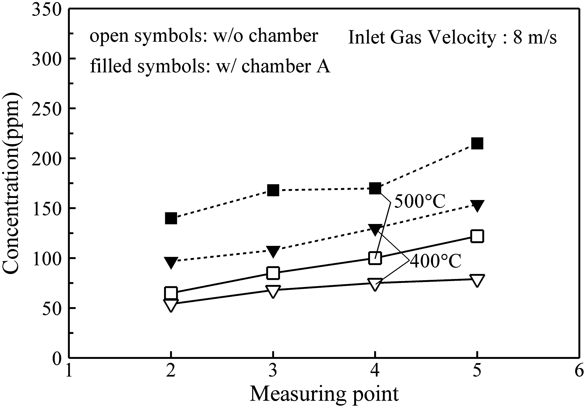
NH3 concentration profiles along the pipe with respect to the inlet gas temperature at a fixed inlet velocity of 8 m/s with an A-type mixing chamber: open and filled symbols denote NH3 concentration without and with an A-type mixing chamber, respectively.
Effects of inlet gas velocity and temperature on urea thermolysis with the B-type mixing chamber
The characteristics of urea thermal decomposition with the B-type mixing chamber are examined for inlet gas velocities of 4 and 6 m/s, and for temperatures of 400°C and 500°C.
Figure 10 shows NH3 concentration profiles along the axial distance with and without the mixing chamber for variable inlet gas temperatures at the inlet gas velocity of 4 m/s. At inlet gas temperatures of 400°C and 500°C, the average NH3 concentrations with the mixing chamber over all measurement points are about 164% and 192% higher, respectively, than those without the mixing chamber. The NH3 concentrations at the fifth measurement point are 178 and 293 ppm for the respective inlet gas temperatures, and these are about 187% and 184% higher, respectively, than those without the mixing chamber.
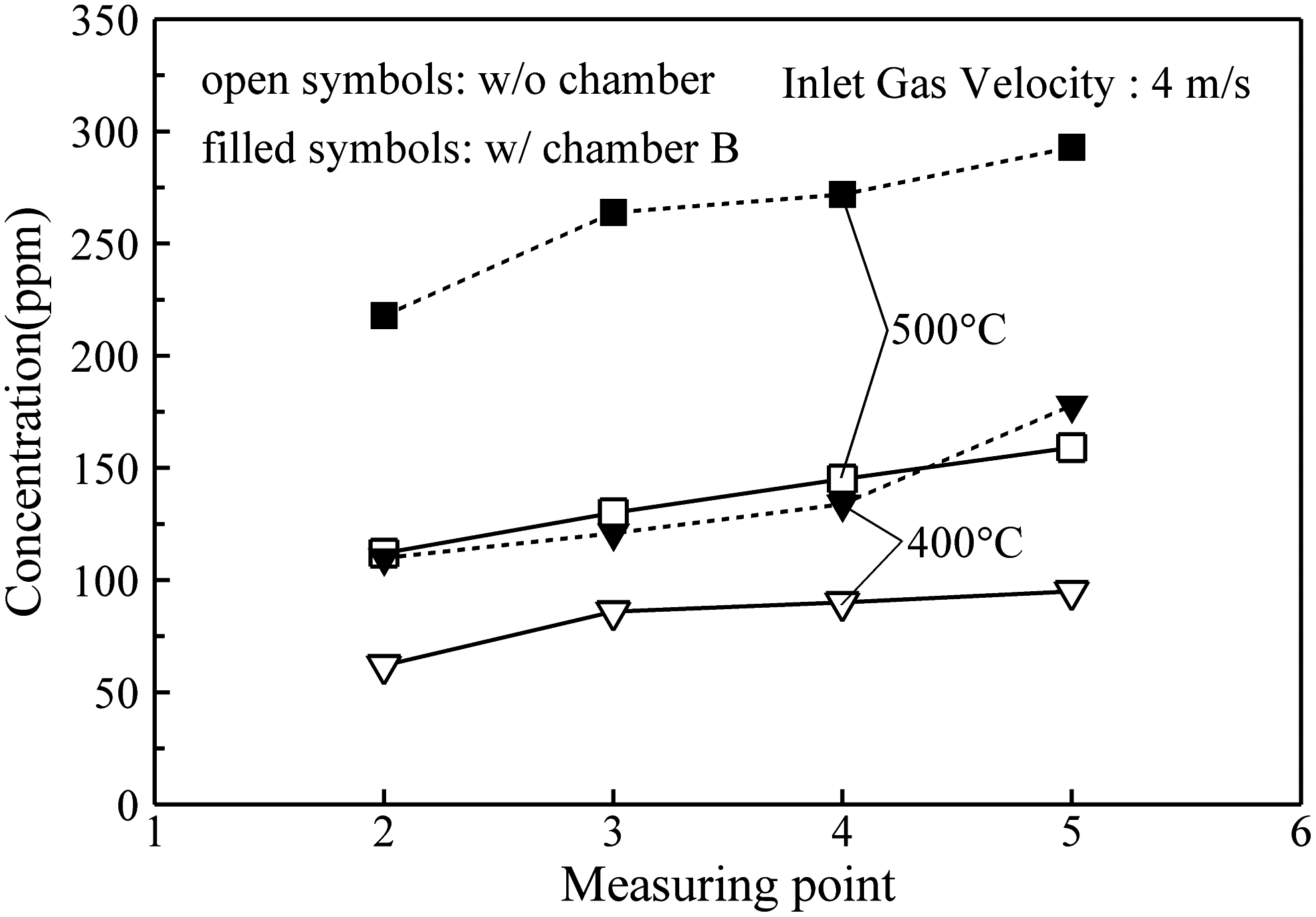
NH3 concentration profiles along the pipe with respect to the inlet gas temperature at a fixed inlet velocity of 4 m/s with a B-type mixing chamber: open and filled symbols denote NH3 concentration without and with a B-type mixing chamber, respectively.
Figure 11 shows NH3 concentration distributions along the distance at an inlet gas velocity of 6 m/s. For inlet gas temperatures of 400°C and 500°C, the average NH3 concentrations with the mixing chamber are about 147% and 179% higher, respectively, than those without the mixing chamber. For the respective inlet gas temperatures, the NH3 concentrations at the fifth measurement point are 128 and 250 ppm, respectively, and these are about 154% and 172% higher, respectively, than those without the mixing chamber. At the inlet velocity of 6 m/s, the thermal decomposition rate with chamber A is better than with chamber B at gas inlet temperature of 400°C, but chamber B exhibits a better thermal decomposition rate than chamber A at a gas inlet temperature of 500°C. The contact area of the B-type mixing chamber is greater than that of the A-type chamber. It is obvious that a high temperature and a high contact area are better for thermal decomposition and vice versa. However, more detailed heat and fluid flow analyses at different temperature conditions are essentially required to clarify the thermal decomposition characteristics of two mixing chambers in future work.
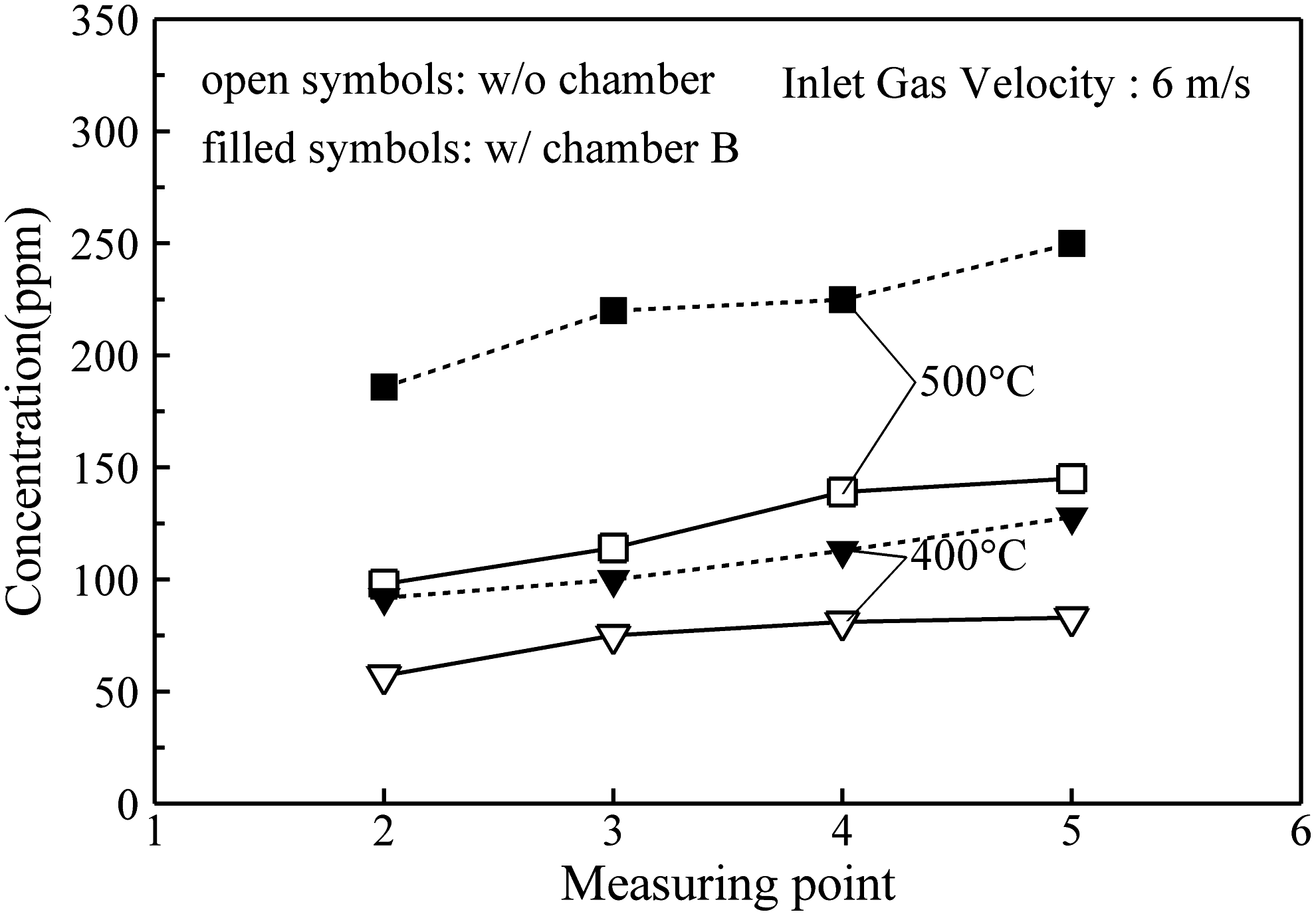
NH3 concentration profiles along the pipe with respect to the inlet gas temperature at a fixed inlet velocity of 6 m/s with a B-type mixing chamber: open and filled symbols denote NH3 concentration without and with a B-type mixing chamber, respectively.
Conclusions
In the present work, two types of mixing chambers are designed and fabricated to improve urea thermal decomposition, and experiments with and without a mixing chamber are carried out to analyze the thermal decomposition characteristics of urea in a chamber exhaust pipe by varying inlet gas velocity (4–12 m/s) and temperature (350°C–500°C).
The NH3 concentration from urea thermal decomposition increases with increasing inlet gas temperature due to the activation of urea thermolysis and with increasing axial distance from the injection nozzle of the urea–water solution because of an increase in the residence time of urea in the exhaust pipe. At inlet gas temperatures below 350°C, however, the NH3 concentration is very low due to the deactivated thermal decomposition of urea. The NH3 concentration is also low at the inlet gas velocity is 12 m/s regardless of the inlet gas temperature and measurement point because of the shortened residence time of urea in the exhaust pipe. When the inlet velocities are 6 and 8 m/s, the average NH3 concentrations over all measurement points are about 170% and 177% higher with the A-type mixing chamber, respectively, at the inlet gas temperature of 400°C and are about 157% and 164% higher, respectively, at the inlet gas temperature of 500°C compared to those without the mixing chamber.
At inlet velocities of 4 and 6 m/s, the average NH3 concentrations with the B-type mixing chamber increase by about 164% and 147%, respectively, at the inlet gas temperature of 400°C and by about 192% and about 179%, respectively, at the inlet gas temperature of 500°C compared to those without the mixing chamber.
Footnotes
Acknowledgments
This research was supported by the Basic Science Research Program through the National Research Foundation of Korea (NRF), funded by the Ministry of Education, Science and Technology (2009-0077771).
Author Disclosure Statement
No competing financial interests exist.