
Abstract
Abstract
Analytical models of floc characteristics are developed as components of a comprehensive flocculation model. The models are derived for reactors with a high ratio of advective fluid transport relative to diffusion (i.e., high Peclet number) and batch reactors where the floc size distribution is expected to be relatively narrow compared with completely mixed flow reactors. High Peclet number flows are obtained in gravity-driven hydraulic flocculators without mechanical agitation. Hydraulic flocculators are an ideal technology for a low carbon footprint and where robust, low maintenance operation is required. The models, combined with measurements of floc sedimentation velocity and floc volume fraction, suggest that the fractal dimension of flocs is approximately 2.3 and that 0.65–1 μm is approximately the particle size beyond which fractal geometry is needed for description of floc properties.
Introduction
H
Models that describe the flocculation process and the capabilities of hydraulic flocculators are needed to create a rational basis for design. The flocculation process is difficult to model because the floc sizes evolve over a scale ranging from micrometers to millimeters. The flow field at the particle level can be laminar or turbulent. In addition, floc density and the floc volume fraction are known to vary with floc size. These complications have precluded the development of simple analytical models that describe the entire flocculation process.
Hydraulic flocculators with their long serpentine flow path and absence of mechanical mixing may be idealized as arbitrary flow reactors with high Peclet numbers (i.e., a high ratio of fluid transport through advective flow to transport through diffusion), and thus it is reasonable to simplify the problem by assuming that floc size increases as particles travel along the flow path and to assume that only a narrow floc size distribution exists at each location in a hydraulic flocculator. The size of flocs varies from the source water colloids that are about 1 μm in diameter to the final flocs that are about 1 mm in diameter. Thus, the floc volume increases by a factor of a billion through the flocculator. At any given location in the flocculator, there will be a distribution of floc sizes. There will be a strong tendency for the floc size distribution to stay narrow because flocs smaller than the mean will have a high probability of colliding with a larger floc. Similarly, flocs that are larger than the mean will have a high probability of colliding with a smaller floc. The result will be that the floc size will grow rapidly through the flocculator and the floc size distribution will be relatively narrow. The relatively narrow size distribution that is a characteristic of plug flow or batch reactors has important consequences both for the fractal characteristics of the resulting flocs and for the reaction times required to form flocs that can be removed by sedimentation.
In this article we explore the fractal nature of flocs formed by hydraulic flocculators in water treatment systems. Analysis of floc settling velocities and floc volume fraction each provides a basis for determination of the fractal dimension and the minimum particle size at which application of fractal geometry to aggregates is appropriate. The fractal model equations provide estimates of floc properties as a function of floc size and, thus, can be used as inputs to performance models for subsequent unit processes.
Fractal Geometry
As flocs collide and grow, they become more porous, less dense, and the total floc volume fraction grows. Floc aggregates can be represented as fractals (Meakin, 1988; Bache and Gregory, 2007). The floc fractal dimension controls the resistance to fluid flow through the aggregate as well as the fluid collection efficiency (Veerapaneni and Wiesner, 1996). The diameter of a fractal floc (d) containing i primary particles (i.e., raw water colloids and initially precipitated coagulant such as Al(OH)3(s)) is
where d0 is the size of the primary particles and DFractal is the fractal dimension. Similarly, the number of primary particles in a fractal floc of diameter d is (Gmachowski, 2000)
Primary particles have a fractal dimension of 3, but aggregates of the particles have a lower fractal dimension. Meakin (1988) determined that flocs with two contact points have a fractal dimension of 2.13 and flocs with three contact points have a fractal dimension of 2.19. Lambert et al. (2003) found that the fractal dimension of Escherichia coli flocs ranged from 1.90 to 2.20. Jarvis et al. (2005) report that values of the fractal dimension range from 1.66 to 2.56 for coagulated natural organic matter. Nan et al. (2009) reported the fractal dimension of optimally coagulated clay suspensions to be 2.2. Li and Ganczarczyk (1989) analyzed fractal dimensions of aggregates based on reported settling tests and size–density relationships and determined a fractal dimension of 2.3 for alum aggregates.
The fractal dimension of a cluster that is created by many sequential collisions is determined by the type of collision trajectory and by the relative sizes of the colliding particles. Particle collision trajectories are categorized as diffusion or ballistic. Diffusion trajectories have random direction changes, with the changes in direction occurring over distances that are small relative to the size of the colliding clusters. The frequent direction changes result in dendritic forms with a more porous structure and hence a low fractal dimension. Ballistic trajectories are straight and result in a much less porous structure (Meakin, 1988).
Clusters that form exclusively through ballistic collisions of particles that are very different in size will have a fractal dimension approaching 3 (Gmachowski, 2006) because the aggregate porosity would be expected to be independent of size and related only to the packing of the smaller particles. Gmachowski derived an analytical relationship for the fractal dimension of clusters obtained from either diffusion or ballistic trajectories as a function of the ratio of the sizes of the two colliding clusters. This analysis showed that the fractal dimension increases smoothly as the ratio of the size of the colliding clusters increases. Thus, the fractal dimension of flocs is expected to be affected by the particle size distribution in the flocculator.
The analysis by Gmachowski (2006) suggests that serpentine path reactors that are designed to approach plug flow (such as hydraulic flocculators where floc particle growth increases with distance traveled) and batch flocculators (where the size of flocs increases over time) produce flocs with a lower fractal dimension than completely mixed flow reactors. The standard Jar Test apparatus that uses batch treatment is expected to produce flocs with a fractal dimension that is closer to serpentine flow reactor flocs than it is to completely mixed flow reactor flocs. Experimental results from completely mixed batch reactors (flocculation occurring as a function of time) and laminar flow tube flocculators (flocculation occurring as a function of location) will be used here to obtain estimates for sedimentation velocities and floc volume fractions.
Floc Density and Sedimentation Velocities
Measured floc sedimentation velocities can be used to determine the fractal dimension and diameter of the primary particles. Given the assumption that primary particles at the end of rapid mix do not contain significant water and have a fractal dimension of 3, then the particle volumes are conserved upon aggregation. For purposes of discussion, we assume the initial suspension contains colloidal clay particles and precipitated coagulant (Al(OH)3(s)). The clay particles are not spherical and the diameter used to characterize their size is the diameter of a sphere with equivalent mass so that mass conservation is obtained in the subsequent analysis. The initial density of the floc particle (
where the concentration of the solids in the initial floc (
The mass of a fractal floc containing i primary particles (
where
The predicted floc density can be used to estimate the floc sedimentation velocity. The terminal velocity, Vt, of a suspended particle is given by
where g is gravitational acceleration and CD is the coefficient of drag.
The coefficient of drag in flow regimes ranging from laminar to fully turbulent is given by
where Φ is a shape factor and Re is the Reynolds number.
The shape factor, Φ, in Equation (8) adjusts the coefficient of drag for nonspherical geometry and, according to Tambo and Watanabe (1979), has a value of 45/24 for flocs. The Reynolds number, Re, defined for the terminal velocity, Vt, is given by
where ν is the kinematic viscosity of the fluid.
Although the Reynolds number corresponding to the terminal velocity of a large floc is greater than 1, Wu and Lee have shown that the drag coefficient for porous flocs continues to be inversely proportional to the Reynolds number up to at least 40 (Wu and Lee, 1998). Thus, Equation (8) for porous flocs can be simplified to
Equations (9) and (10) when substituted into Equation (7) give
Equation (11) can be written to show explicitly the effect of the fractal dimension on terminal velocity by substituting Equation (6) for the buoyant density term.
Equation (12) simplifies to Equation (11) for the case of a fractal dimension of 3.
Adachi and Tanaka (1997) derived the following empirical relationship between the diameter of an alum–kaolin floc and its sedimentation velocity (Vt):
where df is the floc diameter based on its downward projected cross-sectional area.
Equations (12) and (13) can now be compared to determine the fractal dimension and the diameter of the initial particles that form the fractal flocs. In Equation (12),
Setting DFractal to 2.38, the initial particle diameter, d0, calculated using Equations (12) and (13), is ≈0.65 μm. While this primary particle size seems reasonable for initially precipitated Al(OH)3(s), a primary particle size closer to 1 μm may be more accurate for suspended microorganisms and clay particles. Although the Adachi data are extrapolated to estimate the primary particle diameter, the constant fractal dimension model used here may not accurately describe the first few collisions. Thus, the extrapolation to a primary particle diameter may not be entirely justified. If do is assumed to be 1 μm, the best fit to the Adachi data is obtained with DFractal = 2.3. Thus, the fractal dimension is not particularly sensitive to reasonable variability in the initial size of particles. Assuming some experimental error was associated with the reported exponent of 1.379 for df in Equation (13), arriving at values for DFractal between 2.4 and 2.3 and a do value ranging from 0.65 to 1 μm demonstrates that the model is providing results that are consistent with previous researchers.
Hydrodynamic forces, gravity, and the inertia of molecules all influence particle aggregation (Elimelech et al., 1995) and the resulting fractal dimension. On the basis of the model of Gmachowski (2006), a fractal dimension of 2.3 suggests collisions between clusters with diameters within a factor of 7 of each other. However, Gmachowski's model did not include the effect of cluster rotation after initial impact to increase the number of contact points, and thus, he estimated that collisions between same-sized clusters would produce a fractal dimension of 1.85, a value that is significantly lower than the values obtained by Meakin (1988) for two and three contact points. Thus, it is likely that the cluster size ratio required to produce a fractal dimension of 2.3 is smaller than the factor of 7 predicted by Gmachowski (2006).
Given a fractal dimension and alum to clay mass ratio, it is possible to calculate the floc size that corresponds to a Reynolds number of 40 (Wu and Lee, 1998) to set the maximum floc size that can be described using Equations (10)–(12). Assuming the fractal dimension is 2.3 and the alum to clay mass ratio is 0.45 suggests that a 2.8 mm diameter floc will have a sedimentation velocity of 14 mm/s and a Reynolds number of 40. Thus, the very largest aluminum hydroxide–clay flocs that can be described by Equation (12) are approximately 2.8 mm in diameter. Larger flocs will have lower terminal velocities than those predicted by Equation (12).
Floc Volume Fraction
Model calculations and measurements of floc volume fraction provide an alternative basis for estimating the fractal dimension of flocs. The floc volume fraction, φFloc, is related to the concentration, CFloc, and density of material, ρFloc, contained in the flocs:
where
Assuming that primary particles in the floc model are composed of clay and aluminum hydroxide, as would be the idealized case with the use of alum to treat a turbid surface water, substituting Equations (3) and (4) into Equation (14) gives (Letterman and Iyer, 1985)
This definition assumes that primary particles at the beginning of flocculation do not contain water. This assumption seems reasonable for clay particles, but it is not entirely clear how to characterize the aluminum hydroxide precipitate at the micrometer scale. An aluminum hydroxide molecule has a dimension that is less than 1 nm. If aluminum hydroxide molecules aggregate randomly to form an amorphous solid, then the primary particles that are generated in the rapid mix process would be porous and have a larger floc volume fraction than that of the starting molecules.
For the model presented here, we assume that the spacing between aluminum hydroxide molecules and the corresponding floc volume fraction is constant as long as molecular diffusion is the dominant transport mechanism. Diffusion provides the mechanism for aluminum hydroxide molecules to aggregate into the lower energy solid phase. In addition, we assume that as aluminum hydroxide particles grow larger than the diffusion limit, they no longer rearrange on contact to form a compact solid and thus their fractal dimension decreases. The estimate of 1 μm, as the particle size at which the fractal dimension changes from 3 to a lower value, is consistent with a floc size that is no longer greatly affected by diffusion.
The ratio of the floc volume fraction containing i primary particles to the initial floc volume fraction is equal to the ratio of the volume of the floc containing i primary particles to the total volume of the primary particles in that floc.
After substituting for i using Equation (2), Equation (16) simplifies to
Model predictions, based on Equation (17) and two alternative approximations of the floc volume fraction derived hereafter, are compared to arrive at an alternative estimate for the fractal dimension of flocs.
One basis for estimating floc volume fraction may be obtained from experimental data for floc blanket growth, where the rate of change of blanket height is observed under conditions with a controlled influent of flocculated particles. Results obtained for a bench scale upflow clarifier are shown in Fig. 1 (Long et al., 2009). These results were obtained in a vertical 10-cm-diameter column fed a raw water with 100 NTU colloidal clay (approximately 100 mg/L clay suspension) that was dosed with 45 mg/L alum and allowed to flocculate in a laminar flow spiral tubular reactor with an average velocity gradient, G, of 83 s−1 and a residence time, θ, of 212 s (Gθ = 17,500) before introduction to the upflow clarifier. The column upflow velocity was 1.16 mm/s. The floc blanket growth rate was measured using pictures taken with a webcam with a resolution of ± 5 mm. The observed rate of change of floc blanket thickness was ≅ 50 μm/s (Fig. 1) with an r squared value of 0.9945.
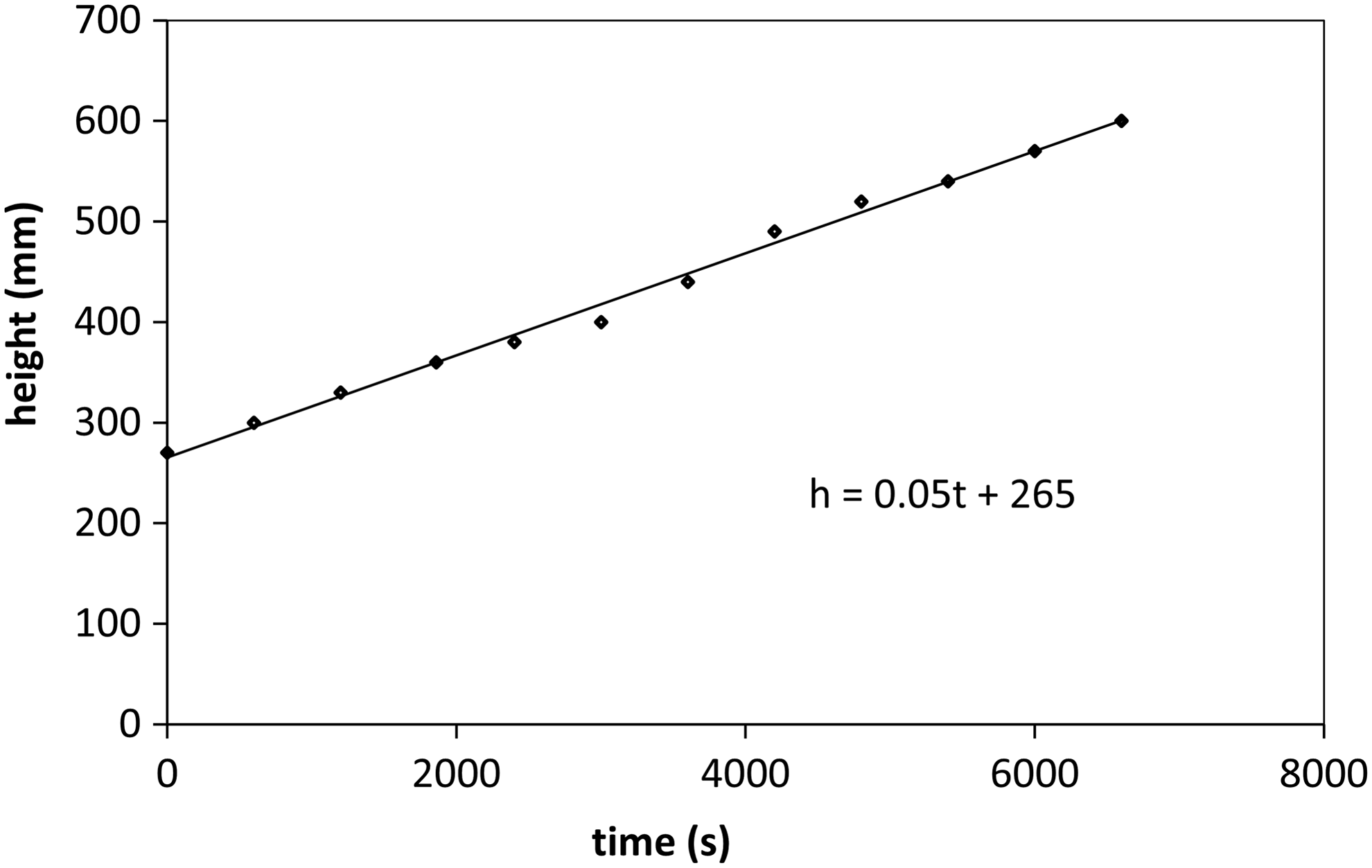
Floc blanket height as a function of time during floc blanket growth (Long et al., 2009).
The floc blanket volume fraction in an upflow clarifier is given by
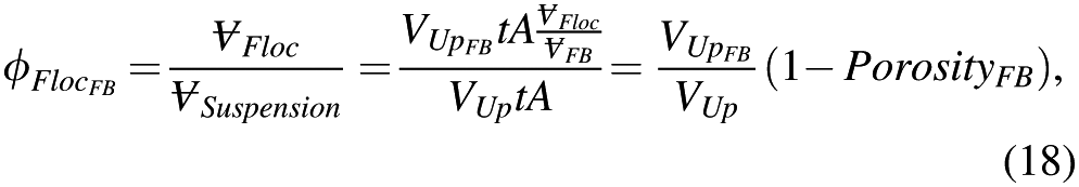
where
A relationship developed by Letterman and Iyer (1985) provides a second measure of floc volume fraction.
where
Calculations of floc volume fraction, using Equation (17) and three different fractal dimensions, are compared with the estimate based on the floc blanket observations [Eq. (18) assuming a floc size of 1–5 mm] and the Letterman and Iyer model [Eq. (19)] in Fig. 2. The Letterman and Iyer model does not include floc diameter as a parameter that affects floc volume fraction. However, the validity of the model was checked by Letterman and Iyer using flocs created over a 60-min interval with a velocity gradient of 10 s−1, and thus it is reasonable to assume that the flocs were several millimeters in diameter. The results are consistent with a fractal dimension in the range of 2.1–2.5.
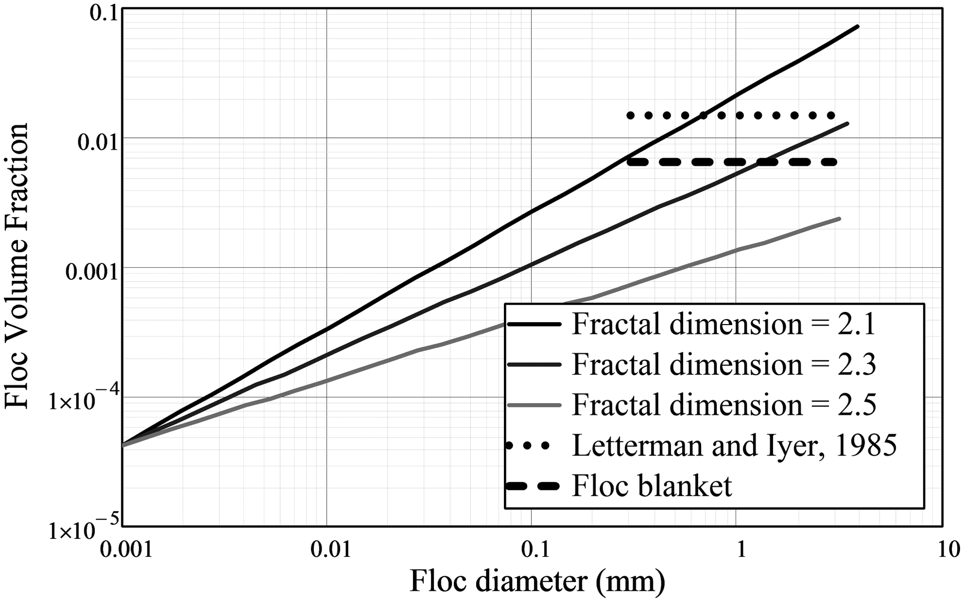
Floc volume fraction as a function of floc diameter and fractal dimension. The concentration of clay was assumed to be 100 mg/L and the alum concentration was 45 mg/L to match the conditions of the floc blanket research. The curves converge at 1 μm, the estimated diameter of the change in fractal dimension.
Conclusions
Three independent sets of data were used to underpin our estimate of the fractal dimension of flocs and models of floc diameter and floc volume fraction. First, the model equations predict reasonable values for floc volume fraction as a function of floc size and are consistent with sedimentation rates of alum–kaolin flocs obtained by Adachi and Tanaka (1997). This data set contained approximately 100 observations and was fit using Equation (13). The second data set consists of the Hurst et al. (2010) experimental measurement of floc blanket growth rate (the time series of data shown in Fig. 1), which is used to determine floc volume fraction. The third data set was the observations of Letterman and Iyer (1985). In this case, 26 observations of the floc buoyant density were used to obtain value of the constant of proportionality, k, in Equation (19). We conclude that the flocs produced in batch reactors or in high Peclet number reactors, where the floc size distribution is relatively narrow, can be described with a constant fractal dimension from the diffusion limit of approximately 0.65–1 μm to the final floc size. Comparisons of model equations to available data suggest that the fractal dimension of flocs is approximately 2.3 and that a 1 μm diameter particle size is the approximate transition from a fractal dimension of 3 to a fractal dimension of 2.3. The model equations are dimensionally correct and require parameters that are easily estimated for typical source water samples.
Footnotes
Acknowledgments
The research described in this article was supported by the U.S. National Science Foundation under Grant CBET-0604566 and the Sanjuan Foundation.
Author Disclosure Statement
No competing financial interests exist.