




Abstract
Abstract
Proper treatment of large amounts of produced water in offshore oil & gas development necessitates the development of advanced water treatment technology. The Compact Flotation Unit (CFU) is a promising technique for removing oil and suspended solids from produced water due to many attractive features such as high separation efficiency, short hydraulic residence time (HRT), and small footprint. In this article, the Machine Learning method (GA-BP neural network model) is used to learn, train, feedback, and predict the correlation between structural parameters and separation characteristics, thus realizing the structural optimization and performance improvement of the device. Mean squared error of GA-BP neural network model is 0.009, and the maximum squared error is 0.028. Separation efficiency of the CFU after optimization can reach up to 92.82%, that is, an improvement of 13.6%. The effects of inlet flow rate, split ratio, and inlet oil content on separation performance of CFU have been predicted. It is showed that when the inlet flow rate increases from 2 m3/h to 6 m3/h, the separation efficiency of CFU decreases greatly. As the split ratio rises from 1% to 8%, the separation efficiency has increased from 89.2% to 95.0%. The rise of split ratio means the increases of hydraulic loading rate in the water clarification zone, which is beneficial to the floating up of oil droplets, thus leading to the improvement of separation efficiency. Increase of inlet oil content is advantageous to promote the collision and coalescence of oil droplets and leads to the improvement of oil–water separation efficiency. Generally speaking, this method can quickly and accurately obtain the influence of structure parameters on separation characteristics, which is helpful to optimize the flow field distribution and improve the performance of related environmental protection equipment, as well as minimize the R&D costs and shorten the R&D cycle.
Introduction
Produced water from production wells is the largest wastewater stream in offshore oil & gas development (Rosli et al., 2011). It is a complicated mixture of organic and inorganic compounds, including dissolved and dispersed oils, heavy metals, radionuclides, formation solids, dissolved gases, and so on. The growing concerns about environmental issues and more stringent legislations on discharge of produced water into the environment have made the management of produced water to be one of the most significant parts in oil & gas industry (Igunnu and Chen, 2012; Li et al., 2016).
Nowadays, conventional methods treating produced water include gravity settling, coagulation sedimentation, centrifugal separation, flotation, membrane separation, and biological method (Fakhru‘l-Razi et al., 2009). Most of the above methods require a long hydraulic residence time (HRT) and a large footprint for achieving desired treatment effect. These requirements can be realized in onshore oilfields where there is no space restriction (Kiuru, 2001). But, in offshore oilfields, the limited space has introduced serious technical, economical, and logistic limitations for operators who design and manage the platform-based facilities (Bridson et al., 2005; Judd et al., 2009).
The Compact Flotation Unit (CFU), which integrates centrifugal separation and flotation separation into a vertical vessel, is a promising technique for removing oil and suspended solids from produced water (Saththasivam et al., 2015). It features very short HRT, high separation efficiency, and low footprint and can well deal with the challenges faced by offshore oil & gas industry (Arvoh et al., 2012).
Since its first application in produced water treatment on the Norwegian Continental Shelf in 2001, more than 20 kinds of CFU products or prototypes have been proposed, such as VersaFlo™, EPCON CFU, TST CFU, CrudeSep®, Cyclosep™ Cophase™, BIPTCFU, and so on (Mohanty and Honaker, 1999; Frankiewicz et al., 2005; Aldaz and Kohatsu, 2013; Bhatnagar and Sverdrup, 2014). However, there are great differences in the microbubble injection system and interior fluid field among the existing CFUs and some even adopt the structure of internal multistage CFU in a single vertical vessel.
The use of CFU shows a great potential in oil & gas industry, especially in offshore oilfields. It is a pity that only EPCON CFU and TST CFU have been widely used in industry up to now, and most of the rest are still in the stage of conceptual design or field trial. Essentially, it is mainly due to that no effective and feasible methods have been developed for the design theory, structure optimization, and performance prediction (Maelum and Rabe, 2015).
For example, Eftehardadkhah et al. (2015) have investigated the influence of interfacial phenomena on the removal of dispersed oil from produced water in a CFU both in the modes of the dissolved and the induced gas flotation, but there is no mention on the structural design and optimization of CFU (Eftekhardadkhah et al., 2015).
Daigle et al. (2012) introduced the working principle and field application of TST CFU, while the effects of the flow field characteristic parameters such as throughput and split ratio (Ratio of oil discharge rate and inlet flow rate) on separation performance of TST CFU have been ignored intentionally (Jahnsen and Vik, 2003; Daigle, 2012). Lee and Frankiewicz (2004) studied the influences of microbubble injection systems and gas injection ratio on separation performance of VersaFlo, but there is no information involved in the design theory of the CFU (Lee and Frankiewicz, 2004). Hayatdavondi et al. (2011) have used the Response Surface Methodology (RSM) to discuss the influences of main structure parameters on separation efficiency of Vorsep.
However, no integrated theoretical design method on the selection of critical parameters such as HRT and surface loading rate has been reported (Hayatdavoudi et al., 2011). Asdahl and Rabe (2013) have developed a control algorithm for the real-time operation and optimization of CFU to reduce the discharge quantity of the oil drain, while no information was involved in the structural design of CFU (Asdahl and Rabe, 2013). Eventually, the lack of fundamental research on the separation mechanism and design theory of CFU has made it that no data can be referred as guidance for the structure design and optimization of CFUs, and resulted in that most of these are still in the stage of conceptual design or field trials, and has greatly hindered the further improvement of separation performance of equipment.
Self-designed BIPTCFU (to distinguish it from other CFUs) is a new kind of CFU and has the advantages of high separation performance, good stability, and flexible operation. The prototypes of BIPTCFU with different rated capacities have been tested in many offshore oil fields such as QHD32-6, LH 11-1,JZ 25-1 of CNOOC (China National Offshore Oil Corp.), and part of the oilfield test results is shown in Table 1 (Cai et al., 2014). Considering that the two-stage series separation efficiency of EPCON CFU is about 65% in Heidrun Extension of Statoil, the BIPTCFU has high separation efficiency and has reached the level of industrialization.
Oilfield Test Results of BIPTCFU Prototype
Taking BIPTCFU as an example, the objective of current work is to describe an integrated structural optimization and performance prediction method of CFU utilizing the fluid mechanics, gas flotation dynamics, Computational Fluid Dynamics (CFD), genetic algorithm (GA), and Back propagation (BP) neural network. The CFD numerical simulation is used to simulate the separation performance of the device, and the Machine Learning Method (BP Neural Network Model Optimized by GAs) is applied to predict the separation efficiencies of BIPTCFUs with different structures and optimize the optimal structure parameters.
It can be expected to determine the suitable flow field distribution based on the flow field characteristic parameters. Thus, the structure of the BIPTCFU will be more reasonable, and the performance will be greatly improved. This structural optimization and performance prediction method can be a good guide to structure optimization design of related environmental protection equipment.
Statement of Theory and Design Process
Process flow and main structure parameters
As shown in Fig. 1, a BIPTCFU mainly consists of a microbubble generator and a vertical flotation vessel. The main function of microbubble generator is to inject microbubbles with high quality into produced water (Kukizaki, 2009; Sadatomi et al., 2012). The vertical flotation vessel is the main equipment for processing produced water. The structure parameters of vertical flotation vessel directly affect the separation efficiency and, thus, need to be designed and optimized intentionally.
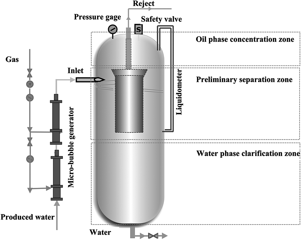
Schematic diagram of BIPTCFU.
The internal flow of the vertical flotation vessel is a multiflow field, including turbulent flow, swirl flow, and laminar flow. Thus, the collision efficiency of droplets in dispersed phase can be improved, and the migration and separation process of different phases can be better guided to ensure a high separation efficiency. According to the function of flow field, the internal flow field in the vertical flotation vessel can be divided into three parts: the preliminary separation zone, the oil phase concentration zone, and the water phase clarification zone.
When produced water containing a large amount of microbubbles flows into the preliminary separation zone through the tangential inlet, swirling flow is formed due to inertia (Fukushi et al., 1995; Kazakis et al., 2008). Owing to the speed difference of oil/gas/water, the collision of oil droplets and microbubble is enhanced, and it could eventually promote the formation of “oil droplets–microbubbles” agglomerates. Relying on the centrifugal force, most of such kind of agglomerates flow along the outer wall surface of the inner concentric cylinder and then enter into the cylindrical space for further separation (Kerdouss et al., 2008). The rest of the water flows into the water phase clarification zone for discharge.
The flow field characteristic parameters in the vertical flotation vessel such as turbulence intensity, HRT, surface loading rate, and swirl intensity are the key factors affecting the separation efficiency. And corresponding structural parameters mainly include the inlet pipe diameter, the internal diameter of the vertical flotation vessel, the width of annular gap, the height of the inner concentric cylinder, and the height of the vertical flotation vessel, as shown in Fig. 2.
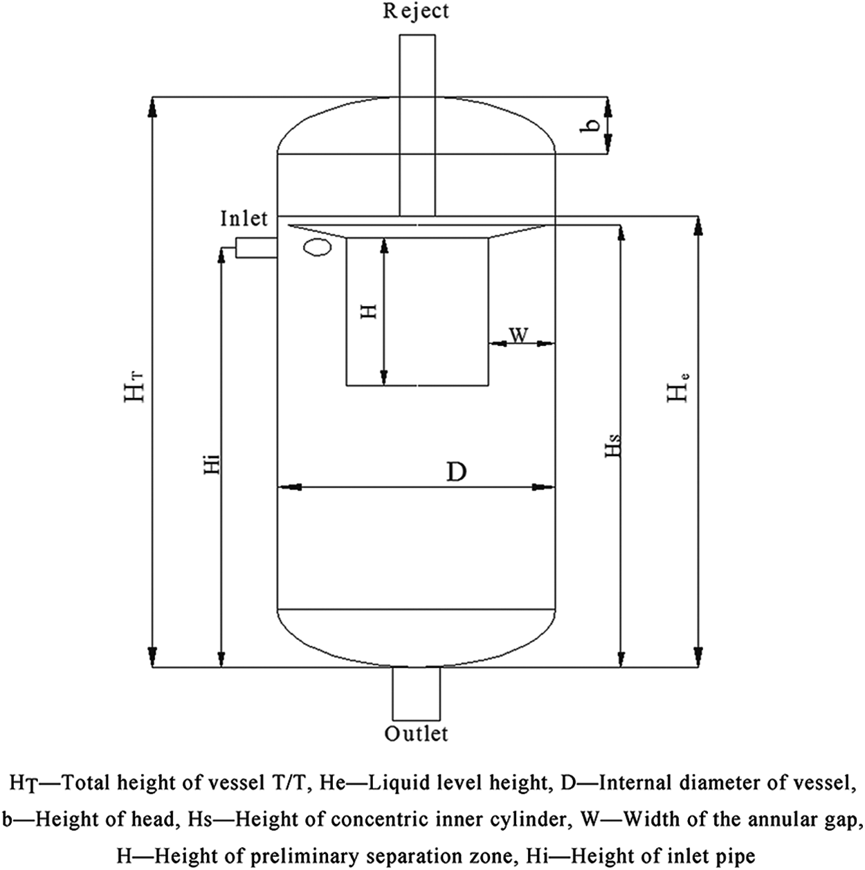
Main structure parameters of the vertical flotation vessel. HT—Total height of vessel T/T, He—Liquid level height, D—Internal diameter of vessel, b—Height of head, Hs—Height of concentric inner cylinder, W—Width of the annular gap, H—Height of preliminary separation zone, Hi—Height of inlet pipe.
Description of design process
Before calculating the size of structural parameters in the vertical flotation vessel, the key design parameters such as inlet flow rate and fluid property should be determined. In this study, the inlet flow rate of produced water Q(m3/h) is assumed to be 4 m3/h, and the rated HRT is 150 s. As to the fluid property, the crude oil density is fixed at 930 kg/m3, the water density is kept at 998 kg/m3, and the water viscosity is set to be 1.1set−3Pa·s. Nitrogen is used as the gas phase and its density is set to be 1.25 kg/m3.
The design process of the vertical flotation vessel is shown in Fig. 3. The volume of the vertical flotation vessel is determined by the inlet flow rate Q(m3/h) and rated HRT t(s). The internal diameter of the vertical flotation vessel is determined by the rated surface loading rate to ensure that most of the oil droplets can float up to the oil phase concentration zone and complete the separation process. The height to diameter ratio is associated with the total volume of the vessel.
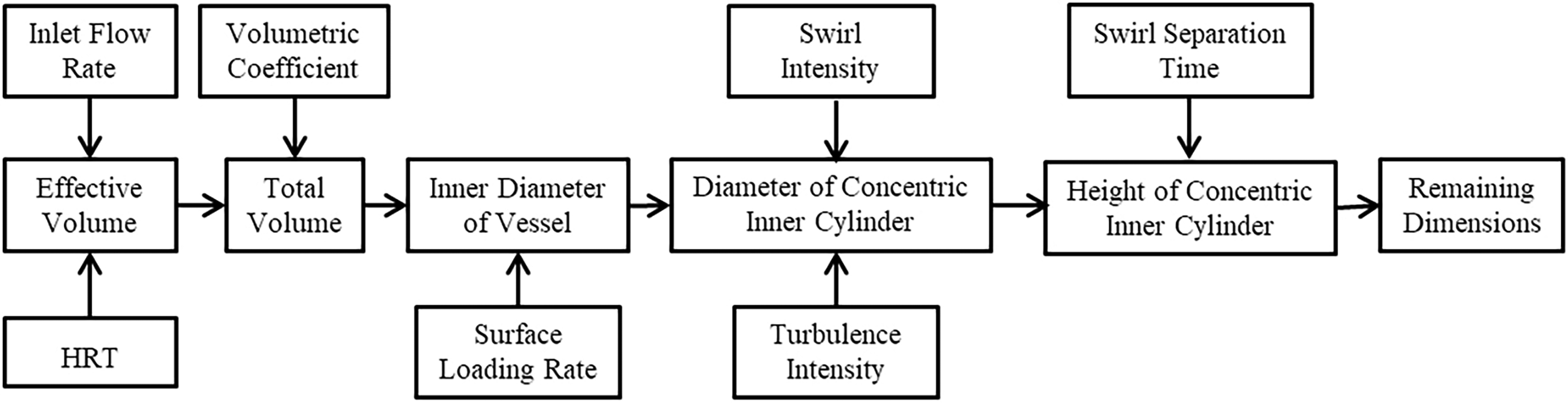
Schematic diagram of the design process for the vertical flotation vessel.
In particular, the annular gap surrounded by wall of the concentric inner cylinder and the inner wall of the vessel is the main place for the centrifugal separation of oil/gas/water. The width of annular gap is determined by calculating the appropriate turbulence intensity and swirl intensity in this region, and the diameter of concentric inner cylinder is the value of the inner diameter of vessel minus the width of the annular gap. The height of concentric inner cylinder can be obtained by multiplying the velocity in the vertical direction of fluid and the swirl separation time that was needed for the oil to migrate to the out wall surface of the concentric inner cylinder in the centrifugal force. The specific calculation steps are as follows.
Determination of inner diameter
As mentioned above, the inner diameter of the vertical flotation vessel is governed by the surface loading rate, which mainly affects the floating rate of dispersed phase (Zeng et al., 2012). The floating rate of dispersed phase refers to the terminal velocity of the bubbles, oil droplets, or “microbubble–oil droplet” agglomerates in the flow field (Ralston et al., 1995). As proposed by Barnea and Mizrahi, the floating rate of the dispersed phase in the turbulent flow can be estimated as follows:
where dp represents the discrete phase diameter, m. ρc represents the density of the water, kg/m3. ρp represents the density of discrete phase, kg/m3. a represents the volume concentration of the discrete phase. g represents the gravity acceleration, m/s2.
Surface loading rate can be expressed as follows:
where Q represents the rate capacity, m3/h. D represents the inner diameter of the vertical flotation vessel, m.
If vp>vs, bubbles, oil droplets, or “microbubble–oil droplet” agglomerates can float up to the oil phase concentration zone and get separated from water phase completely given enough residence time. If vp<vs, they will float down with the main flow and get discharged from the water outlet at the bottom of the vertical flotation vessel (Hoekstra et al., 1999). Since the diameters of most oil droplets within produced water are bigger than 10 μm, the floating rate of “microbubble–oil droplet” agglomerates with diameter of 10 μm is selected to calculate the minimum inner diameter of the vertical flotation vessel. The minimum surface loading rate for the “microbubble–oil droplet” agglomerates with diameter of 10 μm floating to the oil phase concentration zone is 43.2 m3/(m2•h), and the corresponding minimum inner diameter of the vessel is 356 mm.
Determination of concentric inner cylinder
As shown in Fig. 4, the main function of the concentric inner cylinder is to divide the preliminary separation zone into an annular gap and a cylindrical zone. In the annular gap, the swirling flow can greatly improve the collision frequency, coalescence efficiency, and migration velocity of oil droplets and microbubbles, making it easier for oil droplets to attach with microbubbles and float up to the oil phase concentration zone. The cylindrical zone can prove a quasi-static environment for the further separation of oil–water two phase.

Migration principles of “microbubble–oil droplet” agglomerates in annular gap. ut—Tangential velocity, uc—Radial velocity.
When the inner diameter of the vessel is set to be 356mm, the diameter of the concentric inner cylinder is mainly determined by calculating the annular gap width, and the specific calculation process is as follows.
(1) Turbulence intensity
Turbulence intensity, also referred as turbulence level, can be calculated by the following formula (Basavarajappa and Miskovic, 2015),
where I represents the turbulence intensity, %. Re represents the Reynolds number.
Typically, it can be categorized as high turbulence intensity when I is above 10%, medium turbulence intensity as I is between 1% and 10%, and low turbulence intensity when I is below 1%. The increase in the turbulence intensity can effectively promote the collision efficiency of oil droplets and microbubbles, but the shear degree of flow field can also be increased. The fluid shear stress in the turbulent flow can be expressed as,
where ρc represents the density of the water, kg/m3. v is the flow velocity, m/s.
While if the turbulence intensity is too high, it will more easily cause the breakup of “microbubble–oil droplet” agglomerates. Existing research shows that it is better to keep the fluid in moderate turbulence intensity within CFU (Solero and Coghe, 2002).
(2) Swirl intensity
Swirl intensity is one of the measures to evaluate the rotation status of the fluid. Different ways to generate the rotational flow will result in different calculation methods for the swirl intensity (Pednekar, 2008). In this article, the swirl intensity in the annual space is characterized as follows,
where ut represents the tangential velocity of fluid, m/s. r represents the rotating radius of the fluid, m. g represents the gravity acceleration, m/s2.
The main function of the swirling flow is to promote the collision, coalescence, and migration process of oil droplets and microbubbles while ensuring that the shear effect of flow field is not very strong. Through verification, it is found that the swirl intensity is more suitable when it is 5–10.
(3) Swirl separation time
The swirl separation time is the time required for “microbubble–oil droplet” agglomerates to move from the inlet to the out wall surface of the concentric inner cylinder, and it can be expressed as follows,
where S represents the swirl intensity, m/s2. W represents the width of the annular gap, m.
As shown in Table 2, when the inner diameter of the vessel is set to be 356 mm, the inlet pipe diameter is initially set to be 20 mm, the inlet velocity is 3.54 m/s, the initial width of annular gap is set to be 10 mm, and the turbulence intensity in the annular gap is 4.2% according to the calculation equations above.
Major Dimensions or Processing Parameters of Vertical Flotation Vessel
HRT, hydraulic residence time.
Optimization of structure parameters
As the major structure parameters mentioned above are mainly determined by calculating the influence of single factor on the flow field characteristics, the comprehensive effects of these factors on separation performance of BIPTCFU are more complicated and cannot be obtained using theoretical calculation directly. This further restricts the improvement of performance for the BIPTCFU. Based on the calculation results above, the Machine Learning method together with CFD simulation method is used to optimize the structural parameters of the vertical flotation vessel. The CFD simulation method is used to estimate the separation efficiency, and the GA-BP neural network is used to predict the optimal structural parameters according to the estimated separation efficiency.
CFD numerical simulation method
CFD model
All numerical simulations are executed using the numerical simulation software package ANSYS FLUENT 15.0. Currently, the numerical simulation of multiphase flow in ANSYS FLUENT mainly adopts the Lagrangian approach and the Eulerian approach. The Lagrangian approach is a way of considering particles or droplets as a discrete phase and tracking the pathway of each individual particle or droplet as it moves through space and time. The Eulerian approach is a way of observing fluid motion focusing on specific positions in space where fluid flows with time. It is more convenient to study the separation process from the view of fluid field. Thus the Eulerian approach is selected in this article.
Three multiphase models are available in the Eulerian approach: the Volume of Fluid (VOF) model, the Mixture model, and the Eulerian model (Kristianto et al., 2014). The VOF model uses the phase indicator function to track the interface between different phases that are not interpenetrating. The Mixture model and the Eulerian model can be applied to simulate the separation of multiphase flow where phases are interpenetrating.
The Eulerian model, in which all phases are treated as continua, interpenetrating and interacting with each other in the same computational volume, has a better calculation precision. Therefore, the Eulerian model is used in this article, and the governing equations have the following expressions:
where t represents the time, s.
Considering that the collision and coalescence process of oil droplets and microbubbles is still unable to be simulating on an industrial scale in the existing models of ANSYS Fluent, the multiphase separation process of oil/gas/water in the vertical floatation vessel is simplified to an oil–water two-phase separation process (Batchelor, 2000). The densities of water phase and oil phase are set to be 998.2 kg/m3 and 780 kg/m3, respectively. The viscosity of water phase and oil phase is set to be 1.003 and 24 mPa·s, respectively. The effect of microbubbles attaching on oil droplets is considered by properly increasing the initial droplet size to be 300 μm.
In the oil–water two-phase flow, the interphase interaction forces include the drag force, the virtual mass force, and the lift force. Because the lift force and the virtual mass force are smaller compared with the drag force, only the drag force is considered in the CFD Model, and the common expression is as follows:
where
Computational mesh and numerical solution
The preprocessing software Gambit is used to establish the geometric model of the vertical flotation vessel. To improve the computational efficiency and ensure the calculation accuracy, structured hexahedron grid is used in the geometric model (Ji et al., 2016). As to the boundary conditions, the inlet pipe is set to be velocity inlet; the reject pipe and the outlet pipe are set to be outflow; all walls are assumed to be smooth; and no-slip boundary condition is adopted, as shown in Fig. 5.
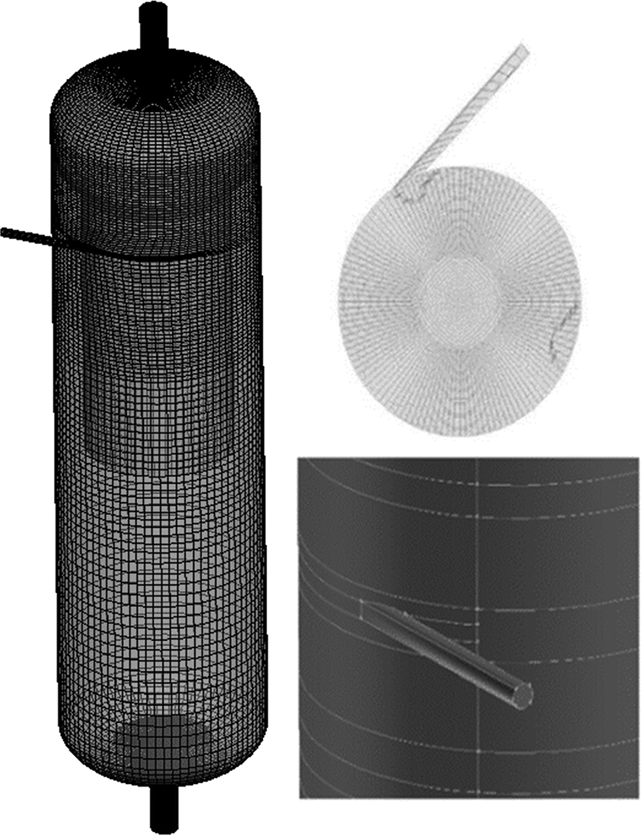
Schematic diagram of the mesh topology.
As to the numerical solution, the Re-Normalisation Group (RNG) k-ɛ model, which is developed using RNG methods to renormalize the Navier–Stokes equations and to account for the effects of smaller scales of motion, is selected to simulate mean flow characteristics for turbulent flow conditions, and the phase-coupled SIMPLE algorithm is used to solve the Navier–Stokes equations.
Regarding the calculation precision and the convergent velocity, the second-order upwind discretization scheme is applied to discretize the equations of the momentum, turbulent kinetic energy, and turbulent dissipation rate. The QUICK discretization scheme is applied to discretize the equations of the volume fraction. The transient formulation is set to be the first-order implicit (Kobayashi et al., 2011). The convergence criterion is set to 1 × 10⁻⁴. The gravitational acceleration is set to be 9.81 m/s2. The time step is set as 1 × 10⁻² s to ensure that the numerical stability and the calculation process stop when the residual error is less than 1%.
During the numerical simulations, the mass flow rates of oil phase and water phase in the pipes of inlet and outlets are recorded. The separation efficiency is defined as follows:
where E represents the separation efficiency, %. Oout represents the mass flow rate of oil phase in the water outlet, m3/h. Oin represents the mass flow rate of oil phase in the inlet, m3/h.
To ensure the calculation accuracy and reduce the computational time consumption, grid independence verification is needed to determine the appropriate quantity of grid elements in the simulation models. When the inlet flow rate is assumed to be 4 m3/h, the oil content in the inlet flow is 200 mg/L and the split ratio is 5%; five models of the same CFU with different grid number about 118,366, 201,040, 362,100, 719,780, and 1,222,560 are simulated, respectively. As shown in Fig. 6, with the increase of grid number, the computational time consumption for the convergence of the simulation results will increase considerably. When the grid number exceeds 719,780, the separation efficiency fluctuates less than 1% and the time consumption is relatively short. Therefore, it is determined that the grid number should be controlled around 719,780 to ensure the calculation accuracy and reduce the time consumption.

Influence of grid number on calculation accuracy and time consumption.
Machine learning method
BP neural network
Back propagation (BP) neural network, as first applied by Rumelhart in 1986, is a multilayer feed forward neural network trained by the Error Back-propagation Training. It can learn and store a large number of mapping relations between the inputs and the outputs without mathematical equation and has currently become one of the most widely used neural network models (Zeng and Chen, 2010). As shown in Fig. 7, the topology structure of BP neural network includes inputs layer, hidden layer, and outputs layer. Considering that the concentric inner cylinder diameter, annular gap width, height to diameter ratio, and inlet pipe diameter are the most important structural parameters that need to be optimized in the vertical flotation vessel, these four structural parameters are set to be the input neurons. The separation efficiency is set to be the only output neuron.

Structure of BP neural network. BP, Back propagation.
GA-BP neural network
The steepest descent method is used in the BP neural network to adjust the weights and thresholds of the network and minimize the error sum of squares. While the initial weights and thresholds of BP neural network are randomly selected, and if these parameters are improper, the convergence rate will be slow and easy to fall into the local optimal value (Kaur and Kumar, 2014). GA is a parallel random search optimization method and has the ability of global search to avoid fall into the local optimal value. Thus, in this article the GA is utilized to determine the initial weights and thresholds of BP neural network, and then the BP neural network is used to search for the optimal value. The complete optimization process of BP neural network combined with genetic algorithm (GA-BP neural network) is shown in Fig. 8 (Ardjmand et al., 2016).

Optimization process of GA-BP neural network. GA, genetic algorithm
Input samples
The input samples should be determined before using the GA-BP neural network for structural optimization. As previously described, the concentric inner cylinder diameter, the annular gap width, the height-to-diameter ratio, and the inlet pipe diameter of the vessel are the key structure parameters of the vertical flotation vessel. Therefore, the critical structural parameters are set as the input neurons of BP neural network. To find out the optimal combination of above four critical structural parameters, the value range of each input neuron has been expanded.
As shown in Table 3, the concentric inner cylinder diameter is ranged between 298 and 354 mm, the annular gap width is in the range of 4–20 mm, and the inlet pipe diameter is set to be 10–20 mm. The height-to-diameter ratio of the vertical flotation vessel is suggested to be controlled between 1 and 5 according to the structural and mechanical design of pressure vessel; the range of this value is selected to be 1.8–4.2. The initial samples of the GA-BP neural network is designed with orthogonal experiment method, and the total group number of orthogonal test is then determined to be 168 using the software of Design-Expert 8.0.6.
Factors and Levels of Initial Samples
For the sake of comparison, the inlet flow rate of the CFU is assumed to be 4 m3/h, the initial inlet oil content is 200 mg/L, and the split ratio is 5% in all simulations; the separation efficiencies of the CFUs corresponding to the input samples of totally 168 groups are numerically simulated one by one.
Analysis of squared error
The GA-BP neural network should be trained and validated before predicting the optimal structure parameters. Groups 1 to 158 in the initial samples are selected as the training samples of the GA-BP neural network to ensure the training quality, and the rest 10 samples are set to be the test samples to test the training accuracy.
The hidden layer node number affects the robustness of the BP neural network, and the best validation performance is 1.6409ts −4 at hidden layer node number 13, as shown in Fig. 9a. The predicted results of the GA-BP neural network model are showed in Fig. 9b and it can be seen that the mean squared error is 0.009 and the maximum squared error is 0.028. The mean squared error is 0.012 and the maximum squared error is 0.047 when BP neural network is used alone. It can be obviously indicated that the prediction accuracy of the GA-BP neural network is superior to that of BP neural network alone and can more satisfy the requirement of optimization.

Analysis of algorithm hidden layer node number and deviation.
Analysis of the Optimization Results
Prediction of optimal structure parameters
Using the GA-BP neural network, the optimal structure parameter combination of the vertical flotation vessel is predicted, and the corresponding highest separation efficiency is 93.89%, as shown in Table 4. To verify the prediction accuracy of the GA-BP neural network, the actual separation efficiency of BIPTCFU after optimization is simulated to be 92.82% and the deviation is only 1.23%. Compared with the separation efficiency of the BIPTCFU before optimization, the separation efficiency of the BIPTCFU after optimization has improved by 13.6%. When using the BP neural network alone, the highest actual separation efficiency of BIPTCFU after optimization is 91.22% and the deviation is 3.34%.
Structure Parameter Combination of BIPTCFU Before and After Optimization
The characteristic parameters of flow field in the vertical flotation vessel are calculated, and the results showed that the total volume is 0.175 m3, the effective volume is 0.158 m3, the HRT is 142 s, and the turbulence intensity and swirl intensity in the annular gap are 9.59% and 8.58 g, respectively. All parameters are within the control range mentioned in the theoretical calculation process, and the HRT of BIPTCFU has been greatly reduced after optimization, which can effectively improve the compactness of the equipment.
As mentioned before, the average separation efficiency of BIPTCFU before optimization in the offshore oil fields is about 91.2%. Considering that the effect of flow field on the separation process of discrete phase is similar both in numerical simulation and field trials, there is still ground for believing that the separation efficiency of BIPTCFU after optimization will significantly be higher than 91.2% (Cai et al., 2017).
Prediction of effect of inlet flow rate
As shown in Fig. 10, the influence of inlet flow rate on separation efficiency of BIPTCFU before optimization and after optimization is predicted at the conditions of 200 mg/L for initial oil content of produced water and 4% for split ratio.
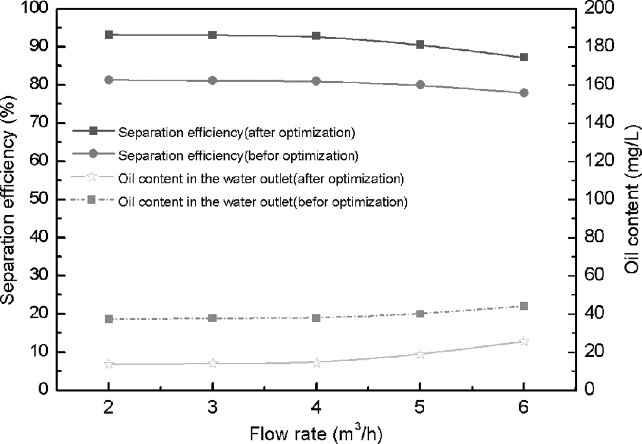
Variation of predicted separation efficiency as a function of inlet flow rate.
It can be seen that when the inlet flow rate decreases from 6 m3/h to 2 m3/h, the separation efficiency of BIPTCFU before optimization increases from 77.92% to 81.34%, and the oil content in the water discharge outlet decreases from 44.16 mg/L to 37.40 mg/L. When the inlet flow rate decreases from 6 m3/h to 2 m3/h, the separation efficiency of BIPTCFU after optimization increases from 87.20% to 93.15% and the oil content in the water discharge outlet decreases from 25.60 mg/L to 13.70 mg/L. The separation efficiency increases rapidly as the inlet flow rate decreased from 6 m3/h to 4 m3/h and then decreases relatively slow as the inlet flow rate continues to decrease to 6 m3/h.
In addition, it can be seen that the separation efficiency of BIPTCFU after optimization is higher by 11.08% compared with BIPTCFU before optimization, and the separation efficiency of CFU after optimization at the inlet flow rate of 6 m3/h is still higher compared with BIPTCFU before optimization at the inlet flow rate of 2 m3/h. It can be concluded that the separation performances, including separation efficiency and handling capacity of BIPTCFU, have greatly improved after optimization.
As shown in Fig. 11, the flow field characteristics such as turbulence intensity and swirl intensity in annular gap are analyzed using numerical simulation. It can be concluded that as the inlet flow rate increases from 2 m3/h to 6 m3/h, the inlet flow velocity rises from 1.77 m/s to 5.31 m/s, and the turbulence intensity rises from 3.4% to 3.9%.

Distribution characteristics of flow field along with inlet flow rates in annular gap.
The shear stress of fluid refers to the shear stress to cause oil droplets to break up (Favero et al., 2015) and can be described as:
where Re represents the Reynolds number. ρ represents the fluid density, kg/m3. v represents the fluid velocity, m/s.
As the inlet flow rate increases from 2 m3/h to 6 m3/h, the increase in the shear stress will promote the breakage of oil droplets, which is not beneficial for the floating process of oil droplets in the oil phase concentration zone and resulted in the reduction of separation efficiency (Liu et al., 2012; Cai et al., 2015).
Prediction of effect of split ratio
As shown in Fig. 12, the influence of split ratio on separation efficiency of BIPTCFU is predicted at the conditions of 200 mg/L for initial oil content of produced water and 4 m3/h for inlet flow rate. It can be concluded that when the split ratio promotes from 1% to 8%, the separation efficiency of BIPTCFU before optimization increases from 78.31% to 86.91% and the oil content in the water discharge outlet decreases from 43.38 mg/L to 26.18 mg/L. As to the BIPTCFU after optimization, the separation efficiency increases from 84.32% to 95.02% and the oil content in the water discharge outlet decreases from 31.36 mg/L to 9.96 mg/L. The separation efficiency of BIPTCFU after optimization under different split ratios is higher compared with BIPTCFU before optimization by 9.81%.
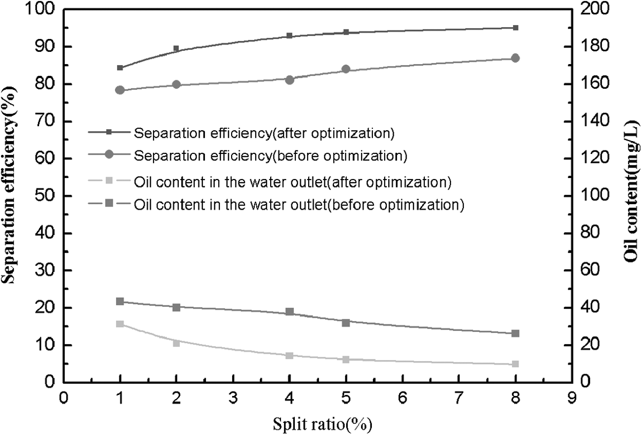
Variation of predicted separation efficiency as a function of split ratio.
The increase of split ratio means the rise of hydraulic loading rate within the concentric inner cylinder in vertical upward direction, and it can ensure that most of the oil phase floats up to the oil phase separation zone and guarantees the enriched oil phase to be discharged in time, thus resulting in the improvement of separation efficiency.
Prediction of effect of inlet oil content
As shown in Fig. 13, the influence of inlet oil content on separation efficiency of BIPTCFU is predicted at the conditions of 4% for split ratio and 4 m3/h for inlet flow rate. It can be seen that when the inlet oil content rises from 100 mg/L to 1000 mg/L, the separation efficiency of BIPTCFU before optimization increases from 75.21% to 85.09% and the oil content in the outlet increases from 24.79 mg/L to 149.07 mg/L. As to the BIPTCFU after optimization, the separation efficiency increases from 85.46% to 94.55%, and the oil content in the outlet increases from 14.54 mg/L to 54.5 mg/L. The separation efficiencies of BIPTCFU after optimization with different inlet oil contents are higher compared with BIPTCFU before optimization by 10.57%.

Variation of predicted separation efficiency as a function of inlet oil content.
Inlet oil content mainly affects the collision and adhesion efficiency of oil droplets in flow field. The collision efficiency of oil droplets is mainly affected by Brown movement, interception, gravity sedimentation, and inertia and can be described as (Patruno et al., 2009):
Where ET is the total collision efficiency, %. ED is the Brown collision efficiency, %. EI is the interception collision efficiency, %. ES is the settlement impact efficiency, %. EIN is the inertia impact efficiency, %.
The increase of oil content in the inlet flow means the improvement of the Brown collision efficiency, the settlement impact efficiency, and the inertia impact efficiency of the oil droplets, which is beneficial to the coalescence of oil droplets. In addition, the annular gap width in the BIPTCFU after optimization is smaller compared with before optimization and it is advantageous to enhance the turbulence intensity in the annular gap and promote the coalescence process of oil droplets, thus resulting in the improvement of oil–water separation efficiency.
Conclusions
Taking BIPTCFU as an example, a separation performance prediction model of CFU is established by means of theoretical design, CFD numerical simulation method, and Machine Learning method. This model is helpful to establish the relationship between structural parameters and separation characteristics of CFU, especially the comprehensive influence of various factors. By analyzing the prediction results of GA-BP neural network, the weight of each factor can be obtained and the optimal combination of structural parameters can be predicted. This separation performance prediction model has the advantages of high prediction accuracy, less capital consumption, and less time consumption and can be used to guide the improvement of separation efficiency for the similar equipment in energy or environment. The main conclusions are as follows:
Using the GA-BP neural network and CFD simulation method to optimize the structural parameters is first applied in the designing of CFU. This method can contribute to the interaction effects, including all flow field characteristic parameters, such as turbulence intensity, HRT, surface loading rate, and swirl intensity on the separation efficiency of BIPTCFU. The predicted results of the GA-BP neural network showed that the mean squared error is 0.009 and the maximum squared error is 0.028. It can be obviously indicated that this optimization method is reliable. After optimizing the structural parameters of the BIPTCFU, the separation efficiency of the BIPTCFU has reached 92.82% and has improved by 13.6% comparing with that of before optimization. The operation flexibility of the BIPTCFU after optimization has also been greatly improved, and the total volume of the vertical flotation vessel has greatly reduced. It indicates that this optimization method can be used to improve separation efficiency and the compactness of all kinds of CFU, including BIPTCFU. The effects of inlet flow rate, split ratio, and inlet oil content on the separation performance of BIPTCFU have been predicted and it showed that the separation efficiencies of BIPTCFU decreased when the inlet flow rate increases from 2 m3/h to 6 m3/h. The separation efficiency of BIPTCFU after optimization under different inlet flow rate is higher by 11.08% compared with before optimization. As to the split ratio, the separation efficiency of BIPTCFU after optimization increases from 89.2% to 95.0% as the split ratio rises from 1% to 8%. The increase of inlet oil content can greatly promote the collision efficiency of oil droplets and improve the separation efficiency.
HT: Total height of vessel T/T, m;
D: Internal diameter of vessel, m;
He: Liquid level height, m;
b: Height of head, m;
W: Width of the annular gap, m;
H: Height of the concentric inner cylinder, m;
Hi: Height of inlet pipe, m;
Ve: Effective volume, m3;
dp: Discrete phase diameter, m;
ρ: Density, kg/m3;ρp: Discrete phase density, kg/m3;
a: Volume fraction;
g: Gravity acceleration, m/s2;
Q: Rate capacity, m3/h;
t: Time, s;
V: Total volume, m3;
vp: Terminal velocity, m/s;
vs: Surface loading rate, m3/(m2•h);
I: Turbulence intensity, %;
Re: Reynolds number;
S: Swirling intensity, %;
u: Velocity, m/s;
r: Rotating radius of the fluid, m;
E: Separation efficiency, %;
Oout: Oil content in the outlet, mg/L;
Oin: Oil content of the initial oily wastewater, mg/L;
a: Volume fraction of oil phase, %;
p: Pressure, Pa;
ET: Total collision efficiency, %;
ED: Brown collision efficiency, %;
EI: Interception collision efficiency, %;
ES: Settlement impact efficiency, %;
EIN: Inertia impact efficiency, %;
Footnotes
Acknowledgments
The authors gratefully acknowledge the support from the Key Project of Beijing Municipal Natural Science Foundation (KZ201410017019), The Importation and Development of High-Caliber Talents Project of Beijing Municipal Institutions (CIT&TCD20150317), and National Natural Science Foundation of China (51806019).
Author Disclosure Statement
No competing financial interests exist.