
Abstract
Leakage of oil & gas during fossil fuel exploration, production, and transportation poses a major environmental challenge that impacts the quality of air, water, soil, and ultimately the life on Earth. The result of uncontrolled spills & leakages may cause the contamination of groundwater as well as methane emission into the atmosphere increasing global warming, while the spills in open waters in the case of offshore wellbores impact fragile marine ecosystems. The United States alone has ∼1.7 million wellbores with an American Petroleum Institute (API) number indicating that they have not been permanently plugged and therefore require Plugging and Abandonment (P&A) in the future. However, there remain thousands of wells drilled before the 1950s that were not properly P&A. Improper P&A of boreholes are potential pathways for leakage as well as already existing leaky plugs. The objective of this literature review is to (1) assess subsurface conditions where P&A materials need to be placed, (2) assess the challenges encountered during barrier placement in wellbores under current P&A technologies, (3) appraise contaminations of barrier materials by drilling fluid and possible mitigation, and (4) discuss the future requirements of P&A materials and technology involved in restoring subsurface sealing barriers interrupted by drilling. The review indicates that to achieve permanent P&A in the future, two major challenges must be addressed: (1) innovation & improvement of the barrier materials, and (2) advancements and innovation of the placement methods. The major insight from this article is that re-establishment of a permanent seal capable of withstanding subsurface geomechanical and geochemical changes will involve engineered materials and processes providing sealing in the early stages (1–50 years) and geomaterials and geological processes take over and provide permanent seals, for thousands of years to geological times. Thus no single solution can be successful for future P&A campaigns.
Introduction
Wellbore leakage is one of the major environmental challenges in the world today, and contrary to common belief, catastrophic events reported by media might not be the most damaging form of leaky wellbores. A good example is a leakage from a Taylor Energy-owned platform in the Gulf of Mexico, which started 15 years ago and was recently estimated to leak between 9 and 108 barrels (378 to 4,536 gallons) a day (Mason, 2019; Wenland, 2019). Over time, the cumulative leaks from the Taylor Energy-owned platform might be comparable to the BP Horizon accident, but only recently has leakage from the platform being reported and investigated by authorities. The Bureau of Safety and Environmental Enforcement (BSEE) (BSEE, 2019; Wenland, 2019) has predicted that if the leaks from the Taylor platform are not mitigated, the leakage can continue for 100 years.
The leakage and spills from wellbores may result in contamination or extensive damage to sensitive marine ecosystems, avian habitats, groundwater, freshwater, soils, methane emission into the atmosphere increasing global warming, and reduction or elimination of the economic power of those who live in regions, such as the Gulf States in the United States. An oil spill is the release of large quantities of liquid petroleum hydrocarbon into the environment and a leak is an unintended seepage or slow release of small quantities of hydrocarbon into the environment over a long period. History continually shows that an idle or improperly sealed well leaks harmful gases or fluids into the environment (King and King, 2013).
In 2010 the BP Deepwater Horizon spill released ∼4.9 million barrels of oil into the Gulf of Mexico (Robertson and Krauss, 2010). In 1979, 4.9 million barrels of oil were spilled into the Bay of Campeche from the Ixtoc I exploratory well (Patton et al., 1981). Poorly plugged buried wells leaking oil, natural gas, and toxic formation waters (water from the geologic layer being tapped for oil and gas) posing a risk for explosion and toxification have been identified around homes and parks in California (Ferrar, 2019). Large threats of leaky wells lie thousands of feet underground and it is tough to detect the migration of oil and other toxic minerals into aquifers or water supplies at this depth since most of the monitoring is done on the surface. Schout et al. (2019) have shown that 1 in 29 wells plugged, abandoned, and buried in the Netherlands leaks.
Also, proper plugging and abandonment (P&A) depend on the boom-and-bust cycles across oil and gas drilling fields. The bankruptcy of a company can cause them to abandon initially owned wells, known as “orphaned” wells. Since 1859, ∼3.7 million wells have been drilled in the United States., and their history is not always well documented (Allison and Mandeler, 2019). Older wells drilled before the 1950s used less rigorous and less durable materials for P&A due to the lack of regulations, leading to some of the leaks observed today. In 2018 the Environmental Protection Agency (EPA) estimated a total of 3.11 million abandoned wells onshore, among which 69% (2.15 million) were unplugged and 31% (0.96 million) plugged between the years 1990–2016 (EPA, 2018). Figure 1 is a bar chart illustrating plugged and unplugged wells in the United States. These abandoned wells are potential sources of groundwater contamination and methane emission into the atmosphere.

Number of oil and gas wells in the United States relevant for P&A. Of all the wells in the United States, only 0.02 million are plugged. The remaining will require P&A in the future. P&A, plugging and abandonment.
In recent years the oil and gas industry has ventured into high-pressure high-temperature (HPHT) acidic environments (Fig. 1), which are more challenging to plug and abandon (examples include the deepwater Gulf of Mexico, off the coast of Brazil and Angola). More frequent leaks and spills that might form a thin film on top of the water surface, known as an oil sheen, prevent oxygen exchange with water, thereby impacting the chemical and physical environment, biosystem, marine ecosystem, and economic activities in those areas. Containing a spill is more difficult than avoiding a spill in the first place; and containing a spill has a longer and less certain impact on the environment than the cost and time required to engineer solutions for safe, economical, and responsible fossil fuel exploration and production.
Drilling technology has evolved from when the first vertical well was drilled to present-day horizontals and multilateral wells. State-of-the-art technology is also applied in complex completion of wells in HPHT reservoirs, environments with salt domes, and hydraulically fractured formations. However, the procedures for plugging and abandoning a well are completely different from those used for drilling and completing the same wells. The entry point of the well is ultimately sealed when it reaches the end of its life and is no longer profitable, depending on the existing price of oil and gas. Permanent P&A are aimed at isolating and sealing the permeable intervals of subsurface rock formation. This is done to prevent the upward flow of subsurface fluids into water aquifers and any discharge to the surface. A stable long-term seal is the benchmark of the success of an abandonment operation. Additionally, this needs to be achieved by following government regulations and meeting all safety regulations essential for environmental protection (Kelm and Faul, 1999). Although P&A has been perceived as a necessity, it has often been postponed and carried out at a minimal cost and without much improvement over the decades Figure 2.
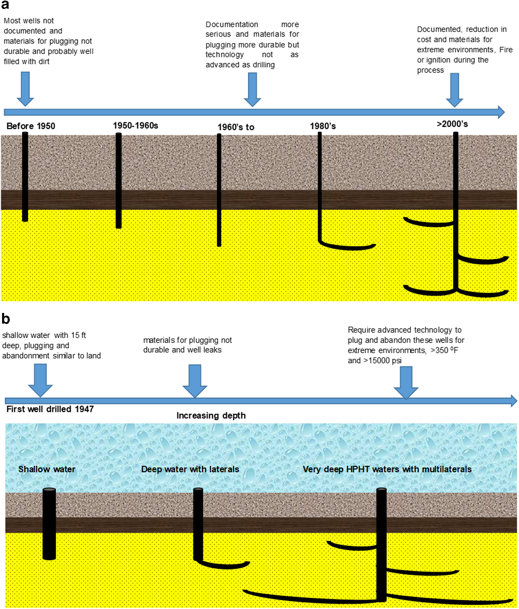
Conceptual models for wellbore P&A shows the expansion of drilling operations into greater depths, and further offshore, as well as change from vertical into directional and horizontal drilling, and introduction of various stimulation and production technologies from acid treatments, hydraulic fracturing, CO2 injection, steam application, and use of nanoparticles, all of which impact wellbore life cycle and ultimately may impact P&A
Cement is commonly used for P&A. The first oilfield cement classification was developed by the American Petroleum Institute (API) in 1952 (Arthur and Hochheiser, 2016). For long-term, traditional P&A jobs, cement may not be ideal, because, during curing, materials can shrink, break, degrade mechanically and/or chemically, and cause leaks into adjacent zones or the atmosphere even a long time after installation (Flopetrol, 2019). Also, the cement may not be resistant to chemicals/substances (H2S, CO2, and hydrocarbons) and the overall pH of the subsurface may be lower than that in cement, which is approximately pH 13. Another common problem that occurs during placement of cement is the loss of hydrostatic overbalance before the material sufficiently solidifies, allowing migration of gas or liquid into the material, resulting in an open channel and development of flow paths.
To achieve permanent P&A and save time and cost, two things need to be considered: improvement to the plugging materials used and placement methods employed as shown in Fig. 3. Plugging materials should not only be durable when exposed to the harsh and dynamic downhole environments but also be compatible with subsurface geochemistry and geomechanics. Currently, cement plugs are the most economical permanent abandonment solution for oil and gas wells and have been widely used for decades (API, 2013). Good cement requires a wide range of additives to improve its performance in a given environment. Improved cement performance can result in (1) higher strengths of cement sheath to provide mechanical support to wells drilled in fragile formations; (2) low permeability of wellbore intersecting caprocks and highly pressurized formations; and (3) increase in well service life in high-risk high-cost operations, such as offshore, extended reach, HPHT wells that demand the highest level of wellbore technology and wellbore intervention available to industry today. Alternative cementitious materials such as geopolymers have been used to improve cement performance since geopolymers are cost-effective and environment friendly. Some companies have designed new materials like Sandaband, which are high-strength quartz particles with Bingham-plastic properties and thermoset (Vignes, 2011). A thermosetting resin system is a plugging material and a potential alternative for P&A and loss circulation.
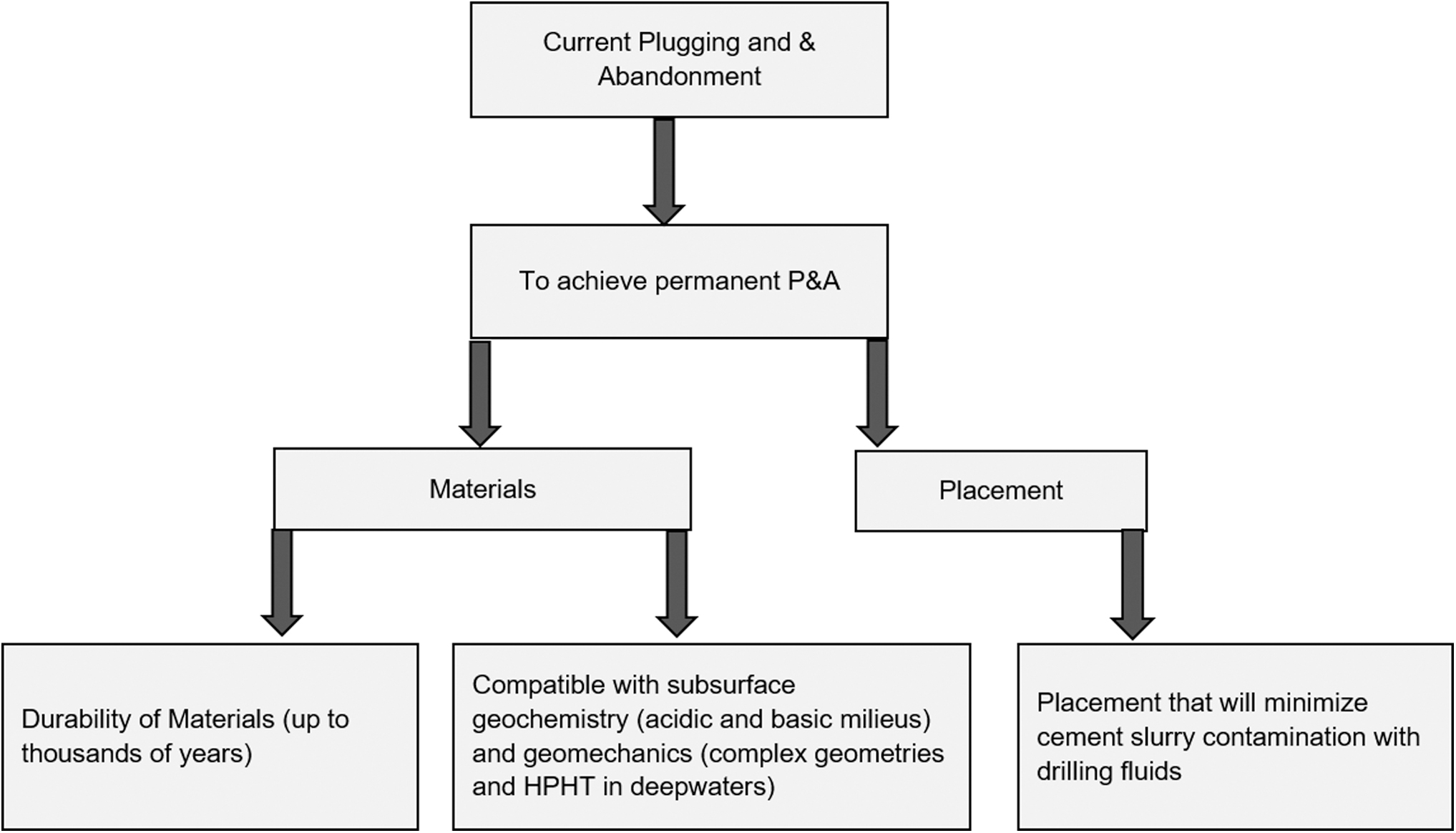
The P&A of future well bores needs to be included in drilling and completions planning, allowing long-term seal barriers as part of drilling cost. In addition, as shown from the diagram above, geological conditions controlled by nature such as geochemistry, geomechanics need to be included in the design/choice of P&A materials and processes, to provide long-term compatibility and durability.
Once the design of the plugging material is defined, the next consideration is to determine the ideal method to place the plugging material in the wellbore to achieve long-lasting integrity. The challenge to the placement methods is the ability to place the plugging material at a specific location and maintain plug integrity without any loss of material properties during the process. The choice and design of plugging materials and the placement cannot be separated from the subsurface conditions, such as pressure, temperature, geochemistry, and geomechanics, which are driven by nature (Fig. 3). At the same time, engineered parameters play an important role, such as wellbore conditions from drilling to completions, reservoir management, and production history.
The objective of this review is to (1) assess the impact of subsurface conditions where P&A materials need to be placed, (2) assess the challenges encountered during barrier placement in wellbores under current P&A technologies, (3) appraise unavoidable barrier material contaminations by drilling fluid and evaluate the possible mitigation of contaminations by incorporating detrimental chemicals as part of the wellbore sealing solution, and (4) discuss the future requirements of P&A materials and the technology involved in restoring sealing barriers in wellbores.
Summary of Current P&A Technologies and Their Evaluation
The balanced cement plug technique has been a frequent method used for the placement of cement plugs from the 1980s up until now (Wilson et al., 2004). Possible sources of cement compromise involve improper cleaning of drilling fluids and debris from the hole. The height of the cement plug in the annulus is supposed to be the same as the cement plug inside for a balanced hydrostatic pressure system (Salahub and Ripley, 1980; Roye and Pickett, 2014). The fundamental assumption of balanced plug calculation is that all the fluids are going to stay in place while the bottom-hole string is pulled through the fluids with a minimal reduction in the fluid level to fill the space left behind by the drill string's displacement (Roye and Pickett, 2014). After that, the pipe is Pulled Out Of the Hole (POOH) at a slow speed to avoid disturbing the established hydrostatic balanced system. If the space of pipe is filled by fluid, then there will be contamination of the cement plug and leakage pathways created. The pulling speeds are regulated at 480 ft/hour (0.04 m/s) to avoid drilling fluid mixing with the slurry (Bogaerts et al., 2012). Thus, there is a need to choose the correct diameter for stinger tubing. Failure to do so leads to an unbalanced system with contamination of up to 40–50% by volume of cement, whereas POOH due to the difference in the volumetric capacity inside the pipe and annulus. The contamination of cement slurry by drilling fluid has a negative impact on the cement plug, mechanical properties that provide resistance to increased pressures/geomechanical changes, and its ability to prevent the flow of various fluids below sealing points into the above rock formation and potential aquifers and uncontrollable release of subsurface fluids.
Density, rheology, surface tension, and flow rate have also been investigated by various researchers, confirming that the eccentricity of the annulus and improper design will lead to wellbore completion/drilling fluids mixing. The effect of density and eccentricity with a new hybrid algorithm considering both Newtonian and non-Newtonian fluids (Foroushan et al., 2018) shows that an increase in the eccentricity leads to a decrease in the frictional pressure drop and fluid remains stationary in regions with narrow gaps. An increase in turbulence also changes the response. Eccentricity contributes to poor displacement especially in horizontal well geometries where a liquid remains stationary on the lower side. Also, higher velocities lead to lower viscosities and better displacement of fluids (Dutra et al., 2005).
The reverse cement placement technique was proposed for the deepwater wells in the GoM to avoid residual cement in the subsea tree and plugging of valves in the manifold or the production tubing (Gubanov et al., 2014). The cement is pumped down the production annulus between casing and tubing through perforations and circulated to the production tubing in this reverse circulation method. This configuration does not allow the use of mechanical separators between fluids; thus, there is a high chance of fluids mixing, contamination, and compromise of the cement-plug material properties.
The dump bailer method is applied at shallow depths but can be adapted for deeper depths (12000 ft or 3657.6 m) by adding retarders to cement to match the reservoir pressure and temperature (Herndona and Smith, 1976; Nelson and Guillot, 2006). A measured quantity of cement is placed in the dump bailer, and lowered to the desired depth and dumped on top of the plug. The dump bailer is run on a wireline, and thus, the depth of the plug can easily be controlled.
The two-plug method involves running top and bottom cementing plugs to isolate the cement from the well and displacement fluids. The bottom plug is pumped ahead of the cement slurry to clean the drill pipe wall and the top plug is pumped behind the cement slurry to prevent cement contamination by the drilling fluid. An increase in pressure indicates the plug has reached its sit (Herndona and Smith, 1976; Nelson and Guillot, 2006).
The perforate wash and clean method of cement placement for permanent abandonment involves perforation of the uncemented casing, washing of the annular space, and mechanically placing the cement across the wellbore cross-section in a single run (Ferg et al., 2011).
The different cement and plug placement methods have their advantages and disadvantages and have been summarized in Table 1. The balance plug, dump bailer, and two-plug methods of cement placement exist from the seventies (Herndona and Smith, 1976) and only recently have the perforate wash and clean method of cement placement been developed and still in the trial phase. All these methods have a fundamental problem with cement contamination by drilling fluid and thus the need for the development of advanced methods. With the rapid advancement in present-day technology, state-of-the-art methods have been developed for primary cementing and there is a need to review or completely develop new methods that will solve the problem of cement contamination by drilling fluids during cement placement for P&A.
Cement Placement Methods Used to Plugging and Abandonment Wells
P&A, plugging and abandonment.
Chemical Incompatibility of Plugging Materials and Drilling Fluids
Drilling fluid systems enable drilling and completion of wellbores; they provide wellbore maintenance primarily by keeping formation fluids from invading the wellbore and transporting rock cuttings to the surface. Drilling fluid is based on composition, usage environment, and the costs required for bottom hole integrity. Drilling fluids are typically classified as water-based mud (WBM), oil-based mud (OBM), HPHT specialty products, or synthetic-based mud (SBM) (oil, 2015). (1) WBM is either dispersed or nondispersed clays, calcium treated, contains low amounts of solids, and designed using saltwater or polymer additives. The composition of WBM can be adjusted to maintain specific mud properties, increase the viscosity for hole cleaning, or reduce the fluid loss. (2) OBM is inverting emulsion mud with a base oil as an external phase and dispersed water as an internal phase. Additives for OBM include emulsifying agents (to keep the internal phase of water dispersed) and lime for neutralization. In addition, viscosity enhancers (viscosifiers) are used in OBM to enhance hole stabilization and fluid viscosity when reservoir conditions are harsh, as with deep-water wells or high-temperature high-pressure wells (oil, 2015). (3) SBM classifications are based on generic chemical names like Polyalphaolefin-Based Fluids, Ester-Based Fluids, Linear Alphaolefin-Based Fluids, Linear Paraffin-Based Fluids, Dialkyl Carbonate Fluids, and Ethers and Glycol Ether-Based Fluids (Patel et al., 1999). SBM is often preferred instead of OBM to reduce environmental risks associated with the OBM.
The contamination of cement slurry by drilling fluids during placement and setting of cement plugs is considered a severe challenge (Agbasimalo and Radonjic, 2014; Oyibo and Radonjic, 2014) for both primary cementing and P&A as it might create channels for wellbore leakage (Fig. 4). Cement core can be contaminated from the mixing of cement with drilling fluid or the inclusions of dehydrated drilling fluid and rock cuttings into the cement slurry. Figure 5 indicates contamination by placing partially dehydrated drilling fluid in the cement mold, and the end result is the presence of inclusions in the cement plug. Also, improper filter cake removal (2–5 mm thick) (Ladva et al., 2005), gelled drilling fluid and hydrostatic pressure differentials between the annulus and the pipe (Salahub and Ripley, 1980; Crook et al., 1987) provide unwanted fluid migration pathways leading to leaks. In addition, fluid migration can occur through hydraulic barriers with microstructural imperfections, physical defects within the matrix, or at casing/cement and cement/rock formation interfaces (Oyibo and Radonjic, 2014).
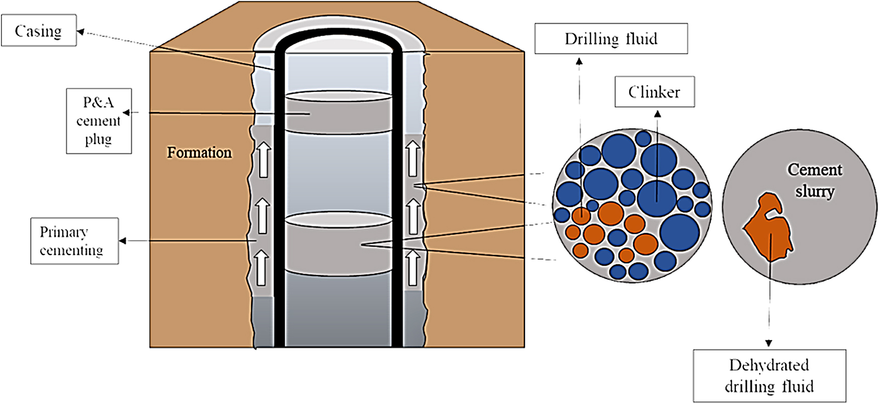
Graphical concept of drilling fluid contamination in primary cementing and P&A.
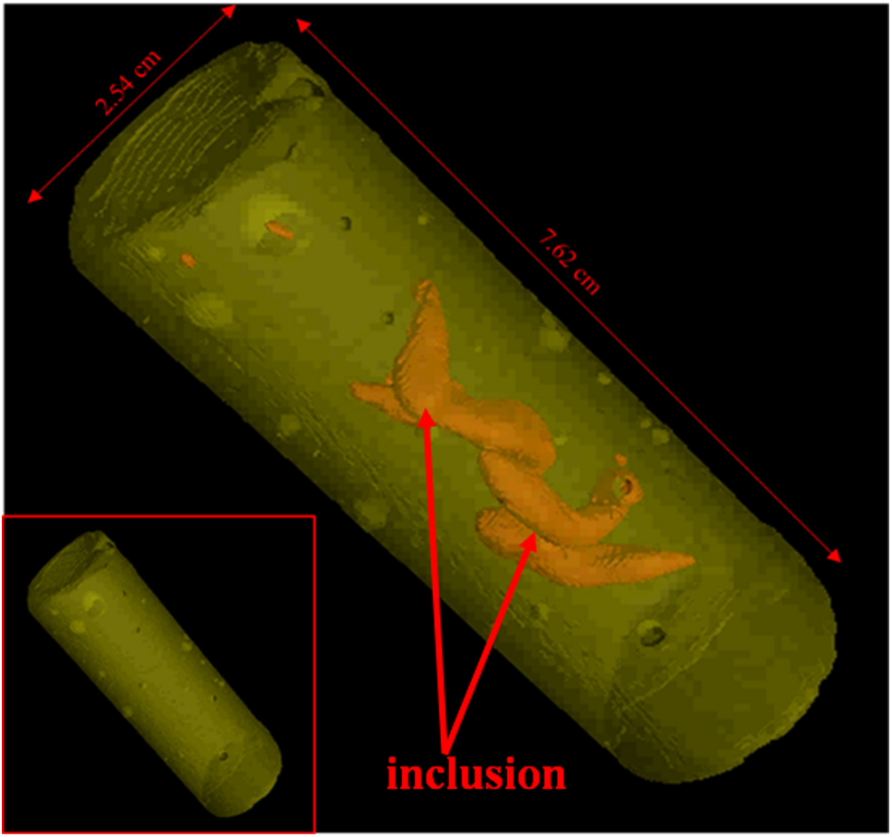
X-ray computed tomography images of a cement core, 2 × 1 inch, 16.4 ppg density slurry of class H cement. The slurry was poured into a brass mold and fragments of dehydrated organic-based drilling fluid were placed into the slurry before curing at 90°C, 95% RH for 30 days, and stored at the ambient condition in pH ∼13 solutions afterward. Image processing was done using Volume Graphics. As can be observed dehydrated oil-based drilling fluid does not react with cement slurry and provides internally weaker zones. The outside appearance of the core, lower left insert, does not indicate the presence of contaminations. RH, relative humidity.
Differences in viscosity and densities can cause an unfavorable interplay between cement slurry and drilling fluid, where the more buoyant fluid rises through the less buoyant (Isgenderov et al., 2015). Since drilling fluids are less dense than cement slurries, they might flow through the cement slurry and form pathways or channels leading to interannular gaps allowing fluids to flow through the cement sheath. Also, drilling fluids tend to adhere to the casing and bottom hole assembly, which makes their removal in preparation for cementing almost impossible. Thus, the presence of drilling fluid (SBM, OBM, and WBM), due to inadequate displacement and insufficient wellbore cleaning, will significantly impact all downhole cementing operations. Contamination leads to changes in the cement sheath's petrophysical and mechanical properties, which might compromise the sealing capability; durability of cement plugs; and rheological, chemical, and mechanical properties. Presently, 100% displacement efficiency and a perfectly clean well are only achievable theoretically but challenging to attain in real-life field operations. The range of displacement efficiency in the field varies from 37% to 99% (Clark and Carter, 1973; Zuiderwijk, 1974; Agbasimalo and Radonjic, 2014). Also, the efficiency of the wellbore cleaning procedure depends on the mud conditioning, casing centralization, fluid density, and flow regime (Nelson, 1990).
Drilling fluid contamination in highly deviated and horizontal wells is a complex issue. The two main problems that significantly affect the cementing operations in deviated wells are solids settling from drilling fluid on the lower side and an excessive free water layer from cement slurry that forms at the higher side of the wellbore (Keller et al., 1987; Borsheim, 2016). The gravity-driven separation of the heavier particles within the mud and lighter free water from cement slurries creates mud channeling or water channeling due to differences in densities. If the solid particles on the lower side of the wellbore are not displaced by cement slurry or cleaning material, a mud channel will remain in the cement sheath leading to inadequate cement plug and incomplete sealing (Crook et al., 1987). The solid particles deposited at the lower side of a well are difficult to remove because of difficulties in washing a deviated well. The adequate yield of washing fluid is necessary to break the gel when the mud has settled to clean the mud. Another solution is to use multiple washers (Yetunde and Ogbonna, 2011). The use of equipment in harsh conditions requires detailed planning and technical expertise as regulations require the plug to 100% encompass the diameter of the hole from the formation casing (Norsok, 2013).
Experimental studies of contamination from SBM and OBM under controlled laboratory conditions have been conducted to determine the impact of drilling fluid on the cement performance and integrity. Partially dehydrated gelled drilling fluid was placed into the cement slurry during the casting of cement slurry into the cement core mold (shown in Fig. 5).
Figure 5 shows drilling fluid mud inclusion within 16.4 ppg Class H, neat cement core after 28 days of hydration under 194°F and 95% relative humidity. From visual inspection, no reaction between the two materials was observed with signs of imperfection on the outer surface of the core (fractures, and volume change). The presence of the inclusion can easily create flows and compromise the key functionality of the cement plug as a barrier material.
Drilling fluid contamination has been reported by several researchers, for example, Miranda et al. (2007) carried out experiments to simulate SBM contamination. The experiments were done on a medium (4-inch internal diameter × 5-ft length) and large scale tubing (36-ft casing with an internal diameter of 12.25-inch and the inside was a 5-inch pipe). Visual inspection of the cement plug showed significant contamination by SBM even with the wash-up of the spacer before the cementing operation. Large fractures and cracks were visible on the cement plug slices. The conclusion was that the cement plugs should always be isolated from any other well fluids by using a spacer or other mechanical plugs to prevent contamination.
Recently, Aughenbaugh et al. (2014) performed compressive strength testing for hardened Class C cement, Class H cement, lightweight cement, and blast furnace slag cement with SBM contamination. It was shown that the compressive strength of all the types of cement decreased with the contamination of SBM due to the chemical reaction between SBM and cement particles during cement hydration. The lightweight cement specifically had the highest decrease (90%) of its original compressive strength while the blast furnace slag proved to have better tolerance to contamination compared with the others. They also found that alkali, as an additive, could mitigate the impact of SBM contamination since it was able to interrupt and invert emulsion. But a question that needs to be addressed is: what is the reaction of cement plugs with unseparated, or in situ produced fluids.
The compressibility of SBM also plays a crucial role in cementing operations. Singamshetty et al. (2004) have quantified the compressibility of SBM. Their study concludes that for different sections of the well the compressibility of the drilling fluid is different and the modeling and the field data from the Gulf of Mexico justifies the claim. Similarly, the compressive or expansion behavior of SBM has been simulated (Shine et al., 2013; Fuller et al., 2014).
Cement contamination by OBM also influences P&A. CA Harder et al. (1993) performed experiments using different OBMs with alkanolamide or standard fatty acid emulsifiers. The compressive strength was measured on a 17.0 ppg Class H cement slurry, which was mixed with varying amounts of the OBMs. Their results suggested OBMs, even at low concentrations, lower the compressive strength value of the cement plug compared with its uncontaminated counterpart. The study discovered that the presence of alkanolamide reduces the impact of OBM contamination of the cement better than fatty acids because alkanolamide is partially water soluble and does not interfere with the cement hydration process. The impact of OBM contamination on 15.0 ppg Class G cement slurries and cores cast from those slurries were analyzed for rheology, compressive strength, and mineralogy with X-ray diffraction (XRD), and texture with the scanning electron microscopy (SEM) (Soares et al., 2017). Soares et al. (2017) showed that the plastic viscosity and yield point of the contaminated cement slurries increased, suggesting a potential risk for pumping the slurry downhole. The compressive strength of the OBM contaminated samples reduced by ∼50% of their original value at 25% volume contamination; the microcavities in the cores observed under SEM justified these results. Furthermore, the Soares et al. (2017) study concluded that the wetting agent in the OBM could modify the value of the zeta potential, compromising the stability and resistivity of the system. However, adding surfactants such as ethoxylated nonylphenols (ENP) will increase water wetting since OBM has a discontinuous water phase that is nearly saturated with calcium chloride (an accelerator) according to Harder et al. (1992). The ENP will further reduce the contamination of OBM.
The mechanism of cement slurry contamination by OBM and SBM has been evaluated by SEM, XRD, and infrared spectrum analysis on kalium polyacrylamide (KPAM), bioviscosifier, and cement slurry with various additives (Zheng et al., 2015). Zheng et al. (2015) postulated that since KPAM and bioviscosifier were both very high-molecular materials, they will easily absorb cement particles into their long chains and form an agglomerated mixed structure. This will cause the cement to lose its pumpability and stability. The SEM images further demonstrated the clumping.
The effects of OBM and its components on the performance of cement slurries have also been studied by Li et al. (2016b). Their results demonstrate that the variations in the rheological properties of mixed cement slurries are caused by the free water from the oil/water or oil/water/oil galactoid structures. This finding suggests the reason for contamination by OBM. The formation of many holes in a hydrated cement matrix and the lubrication effect of the oil phase lead to a reduction in strength and an increase in the porosity.
Nahm et al. (1994), and Hale and Cowan (1991) reported the conversion of designed drilling fluid to cement adding blast furnace slag. This special drilling fluid called universal fluids (UF) was a water-based fluid that would be activated by alkaline materials such as caustic soda and soda ash. The utilization of UF had many advantages, for instance, it was inexpensive and achieved a 100% displacement efficiency as the residual mud and mud filter cake would become integrated as part of the sealing material. The author notes that UF was only applied to some shallow wells with limited mud systems. Also, the tensile strength of the UF may not be enough to hold the pressure for deep wells.
Recently, Liu et al.( 2016, 2017), developed a solidification method by blending different amounts of geopolymer with SBM. A Class H cement with a water/cement ratio of 38.5% was then contaminated with the geopolymer and SBM mixture. Rheology and strength testing showed that geopolymer cement lost 30% of its strength when blended with 10% SBM, while a neat Portland slurry lost 70% of its strength. The authors concluded that geopolymer cement plugs show more tolerance to mud contamination compared with neat Portland cement. They also indicated that altering the mass ratio of geopolymer to drilling fluids could convert different SBM or OBM (Nonaqueous fluids) to cementitious materials and achieve improved mechanical strength.
The main concern is not the lack of studies on how to improve existing plugging materials, such as Portland cement-based slurries, or to develop new composites. The issue is verification and testing of materials at relevant conditions, which include temperature, pressure, exposure to low pH fluids, pressurization and depressurization of reservoirs over time. The current testing protocols were designed for primary cementing, where the life span of cement was 30–50 years and the management of pressurized subsurface fluids. The long-term nature of P&A requires testing that is less focused on strength and more on toughness, self-healing, and self-sealing potential of materials when breached by subsurface fluids, such as CO2-rich brines or methane.
The Next Generation of P&A Materials and Methods for Placement
Current P&A technology has unavoidable limitations on the aspects of placement and material properties as discussed above. The failure of good barrier materials can be attributed to factors such as drilling fluid contamination, mud channeling due to the gravity effect, insufficient mud cake removal, pipe moving effect, and harsh dynamic subsurface environments. Cement is the common material for P&A right now, but cannot be considered as a long-lasting material, especially in deepwater wells in environments that are corrosive, have HPHT attributes. The next generation of P&A requires new technology that will mitigate the above shortcomings. Ideally, this technology should be:
Compatible with rock-formation geochemistry, Unaffected by contamination during placement, such as drilling fluids, cuttings, Capable of achieving long-term isolation through self-healing mechanisms, Environmentally friendly, Capable of installation during drilling and completion before production begins to save on the cost of future operations.
The success of long-term P&A goals will require innovative research drawing inspiration from other fields, such as Civil Engineering, Materials Science, Data Analytics, Artificial Intelligence, and Environmental Sciences.
Three-dimensional and four-dimensional printing technology
Three-dimensional (3D) printing, also known as additive manufacturing (AM), is a “process of joining materials to make objects from 3D model data, usually, layer by layer” (Standard A. F2792 2012). AM has gained increasing attention due to shorter production time and increased product reliability and functionality (Deng et al., 2018). This method allows for the fabrication of complex shapes and structures through computer-aided design (Malda et al., 2013). In the oil and gas field, 3D Printing has been applied to build some accessories such as an ultra-high expansion packer that had over 50% improvement compared with a regular one (Deng et al., 2018). A 3D printed filter designed for a downhole fluid analysis tool and the composite pipe was mentioned in 2016 (Jacobs, 2016). Furthermore, cement performance could be improved by 3D printing, which offers a possibility to provide different kinds of cement at spatially and temporally varying ratios (Hambach et al., 2019). Fiber-reinforced cement was printed that had high flexural strength (up to 30 MPa) and compressive strength (80 MPa). Changing the orientation of the fibers within the structure was shown to be possible (Hambach et al., 2019). The cement mortars reinforced with 3D printed fibers made of polymers and metals are shown to possess high interfacial bond strength (Reddy et al., 2007). The future of P&A materials could be revolutionized by four-dimensional printing, where the fourth dimension is time and implies material evolution and adjustment to surrounding conditions over time. In practice this would mean low solids during placement, expansion to avoid shrinkage and debonding as experienced by cement, and ability to expand and fill in irregularities of wellbore rock walls due to washouts, and ductile under geomechanical variations, to prevent fracturing and fluid flow.
Activating shale rock as subsurface barriers
Shale has proved to form an effective well barrier with the casing from creeping (Stavland, 2017; Vrålstad et al., 2018). The shale rock surrounding the borehole is pushed toward the casing by compressive in situ stresses. Basically, the shale creeps into the casing and fills the annulus and fills the wellbore space over time (Stavland, 2017). An advantage of shale as a barrier material is that it has low permeability of 0.1 nano Darcy for an oil field shale caprock. Some typical overconsolidated shale has a permeability of 0.1 micro Darcy (Horseman et al., 1996) and is the most abundant rock type on the earth, comprising about 75% of the drilled formations. Shale is a clay-rich material defined as a fine-grained sedimentary rock that forms from the compaction of silt and clay-size mineral particles (King, 2005) that contain at least 40% clay minerals compared with nonclay components, such as quartz, feldspar, and calcite (Fjar et al., 2008). The clays allow compaction and good packing of particles due to their morphology, resulting in low porosity and low permeability, which is a requisite for a good seal in the petroleum system (Sakhaee-Pour and Bryant, 2012). Since shale is a good natural seal or barrier, an understanding of its properties will provide better insight for creating effective, practical solutions in P&A. Natural sealing materials are more durable, environment-friendly, self-healing, and stable as they have been caping/storing hydrocarbons and subsurface fluids for millions of years. The high stress-induced self-healing effects are beneficial for a barrier material, and leak rates are low in shale/clay material.116 Knowledge of the shale permeability is important for engineering the sealing properties of plugging materials like shale, however, permeability measurement needs to be accurate (Sakhaee-Pour and Bryant, 2012; Gensterblum et al., 2015; Achang et al., 2017; Sander et al., 2017). The permeability of some extensively studied shales from the North Sea range from 6.5 micro Darcy to 21 nano Darcy (Kristiansen, 1998); the Montney shale permeability range is from 0.0001 micro Darcy to 0.015 micro Darcy, (Moghadam and Chalaturnyk, 2015); Devonian shale cores had permeabilities from 200 micro Darcy to 19 × 10–5 micro Darcy (Luffel et al., 1993). In summary, shale permeability is low enough to trap the hydrocarbons and prevent flow and leakage, but as any nature-made material, it is highly heterogeneous and unpredictable in its properties, due to depositional environment, subsurface fluid migration, and earth stresses. To use shale barriers, each location will require evaluation and long-term laboratory studies and predictive models. Furthermore, just as is the case with Portland cement permeability measurements, sample preparation, type of measurements such as transient versus pulse-decay methods, and use of different fluids will result in discrepancies, which are further questioned if we consider true reservoir pressures and temperatures.
As a result of the sealing capacities of shale over geological time, it has been investigated for in situ plugging by Kristiansen et al. (2018), who studied different activating creep mechanisms in shale: pressure induction, temperature induction, chemical induction, and combined shale creep activation. From models, pressure integrity testing and cement bond log, the pressure-induced mechanism is seen to be the most effective barrier mechanism. The chemically induced mechanism by water is too slow to make swelling result in an effective seal. Fjær et al. (2016); (Kristiansen et al., 2018) added that the best candidate for a shale barrier is one with a low threshold for plastic flow and a high ability to sustain large plastic deformation. In addition, thermo/hydro/mechanical simulation confirms that heat in shale is responsible for a reduction in the borehole radius and sealing of the gap between the well casing and shale formation (Bauer et al., 2017). Consequently, elevated temperatures could result in a significant increase in the creep rate. In addition to the temperature, pressure, or chemical activation, the creep rate is also affected by plasticity and water content. The most active clays have higher creep effects (i.e., smectite > illite > kaolinite) (Ozan et al., 2018). The amount of organic content also affects the rate of creep; as a result, creep deformation is higher when organic content is higher, as observed in hydraulic fracturing of organic-rich shales (Kulhawy and Mayne, 1990). Williams et al. (2009) have identified shale sections good for barriers through wireline logging and pressure testing in some field cases on cement bond log, variable density log, and ultrasonic acoustic impedance scanner. They observed that the shale barrier had sufficient length and azimuthal coverage, which deformed and squeezed tightly to the outside of the casing. To continually investigate shale barriers, (Stenebråten and Bakheim, 2018) have done laboratory tests to simulate and observe the formation of shale barriers in hollow cylinders, as well as stress conditions of the well and the load on the casing. The results point to permanent structural changes the rock suffers during the shale barrier-forming process. However, this is still laboratory work that has to be tested in the field. The concept of activating shale rock as a barrier or re-establishing caprock as a barrier is innovative and requires rigorous verification, testing, and field trials before deployment (Wang et al., 1993; Carragher and Fulks, 2018).
Nano particle enhanced wellbore cements
Cement continues to play a significant and dominant role in well construction and abandonment, as a well-characterized material, compatible with currently used equipment and drilling infrastructure, readily available, and affordable around the globe. However, as the industry moves to more challenging ultra-deepwater reservoirs, emerging technologies are needed to increase the success rate and minimize operational costs (Li et al., 2016a). Nanomaterials have the potential to augment or even replace Portland cement. The particle size of the nanopowder significantly affects the setting and hardening time of cement positively due to its higher specific surface area and electrostatic attractive forces by decreasing the setting time and accelerating the hardening of the cement without significantly affecting the final strength attained (Ginebra et al., 2004). The addition of nano-SiO2 to Portland cement mortars results in a higher compressive and bond strength, both of which are desirable in wellbore construction while providing porosity and permeability reduction as a result of a denser and more compact structure (Sobolev et al., 2009). A plausible explanation is that the nano SiO2 fills up the pores and reduces the production of Ca(OH)2 during hydration (Li et al., 2004; Ji, 2005; Jo et al., 2007; Qing et al., 2007; Stefanidou and Papayianni, 2012). Nanoalumina increased the compressive strength and elastic modulus of mortars (Li et al., 2006). Graphene nanoplatelets increased both compressive and tensile strength by 10–30% for amounts added between 0.3% and 0.9% by weight of cement, without significantly affecting the hydration and stability of hydrated cement (Alkhamis and Imqam, 2018). Less than 5% by weight of cement of silica nanoparticles reduces calcium leaching and decreases degradation, decreases porosity, as well as increases the strength of the cement paste by 30% in cured samples and more than a 100% in asymptotically leached ones (Gaitero et al., 2008). Cement made with nano-SiO2 geopolymer as an additive resulted in increased acid resistance in HPHT experimental conditions compared with the neat Class G cement. As low as 1% addition of nano-SiO2 geopolymer leads to increased strength as well as resistance to minor cracks in acidic environments (Ridha and Yerikania, 2015). Nano-MgO has been used to compensate for short- and long-term cement bulk shrinkage of Class G oil well cement, which could prevent microannular gas flow and reduce nonproductive time due to gas leakage in future wellbores, and provide expansion due to brucite formation that can be quantified and controlled (Mo et al., 2010; Jafariesfad et al., 2016). The cement containing Nano-MgO also has higher mechanical strength in terms of both compressive and tensile strength (Gao et al., 2007; Mo et al., 2010; Jafariesfad et al., 2016). Nanosynthetic graphite has been shown to maintain cement expansion as well; quantities as low as 0.5% in the cement composition are enough for expansion maintenance (Ahmed et al., 2018). Nanocalcium carbonate (CaCO3) in cement improves resistance to oil mud contamination; a 1% addition of nano-CaCO3 and 3% oil mud contamination increases compressive strength by 72% and 10% respectively after 1 and 28 days of curing underwater (Vipulanandan and Amani, 2015). Carbon nanotubes, as a new additive, could reduce gas migration as fracture bridging agents (Rahimirad and Dehghani Baghbadorani, 2012). Similarly, the replacement of ordinary Portland cement by 6% nanoclay (nano metakaolin) improves the compressive strength of cement by 18% compared with the control mix (Morsy et al., 2011). The addition of nano-TiO2 accelerates the hydration process of cement thereby reducing the porosity and enhancing the compressive strength. Thus, accelerated hydration improves the strength of the cement at an early age possibly because of a decrease in the orientation index in Portlandite (CH) (Chen et al., 2012; Meng et al., 2012; Zhang et al., 2015).
Conclusions
Cement degradation causes leakage in plugged and abandoned wells as well as leakage in geologic seals for CO2 sequestration (Kupresan et al., 2013; Scherer et al., 2015). Our review of the current P&A technologies and future options, inspired by the increasing need for environmental protection, has the following conclusions:
Traditional P&A solutions and methods like balance plug, dump bailer, and two plugs, have been used for decades without transformational advancements. This trend is changing, as climate change and a large number of wells needing permanent P&A motivated innovative research and search for novel materials and methods in P&A. However, P&A is significantly lagging behind advancements in drilling and completion technology of oil and gas wellbores. Perhaps an easy solution for rapid advancement in P&A is to expand the wellbore drilling designs to incorporate P&A strategies required at the end-of-well production. The first step toward that is investments in research and development of novel P&A technologies as well as planning for the workforce readiness for the new generation of P&A technology. A good practice might be to design materials and equipment utilized for drilling and completion processes that could be used for the P&A of the well at the end of the production life cycle. This would improve operational efficiency, reduce the cost, and most importantly eliminate the impact on the environment and safety.
The next-generation P&A is likely to use new materials. Some of these solutions such as bismuth and termite technology are early indicators of the upcoming change. Activating shale as a barrier seems like a promising sustainable alternative, but it needs in-depth field testing and verification. Portland cement-based slurries are still the most cost-effective materials used as wellbore hydraulic barriers, and due to the decades of cement use, the amount of research available on cement properties is much stronger than any other material currently considered. However, the stability and integrity of cement plugs are questionable due to its chemical incompatibility with subsurface formation fluids. A potential solution is the combination of engineering materials, such as portland cement-based materials providing barriers initially, and transitioning to a geologically driven solution, such as activated shale caprocks, which will provide a solution over long time periods. Emerging technologies like nanomaterials would only improve the properties of engineering seals over a short period, unless they are designed on principles of geomimicry and transition to geological seals over time.
Another technological opportunity is improving the placement of barrier materials, which involves better cleaning of the wellbore and reduction of drilling fluid contamination/intermixing with barrier materials as they are being placed in the designated plugging position. For example, ultrasonic treatments could significantly improve wellbore cleaning and conditioning before placement of cement that are required for good bonding between cement and the formation/metal casing, although these are even more difficult in horizontal hydraulically fractured wells. The most promising solution that would eliminate the negative impact of drilling fluid contamination is the development of universal drilling to cementing fluid, as it was attempted for water-based drilling mud by intermixing with blast furnace slag slurries.
The last resort in the solution of leaky wellbores is the mitigation that is an intervention to improve the sealing capacity of the materials of choice over time and when required. This would be the last resort, and although not ideal it would be still better and environmentally responsible, rather than ignoring slow-rate long leakage scenarios with impactful consequences on the environment. Currently available technology that is developed in this direction is expandable tubular technology, where the expansion of casing pushes against the formation closing microannular gaps at the interface (Kupresan et al., 2013)
Footnotes
Acknowledgment
The authors are grateful to Pam Reynolds for editorial support.
Author Disclosure Statement
No competing financial interests exist.
Funding Information
The work reported in this publication was supported by the Gulf Research Program of the National Academies of Sciences, Engineering, and Medicine under the Grant Agreement number (G10002358).