
Abstract
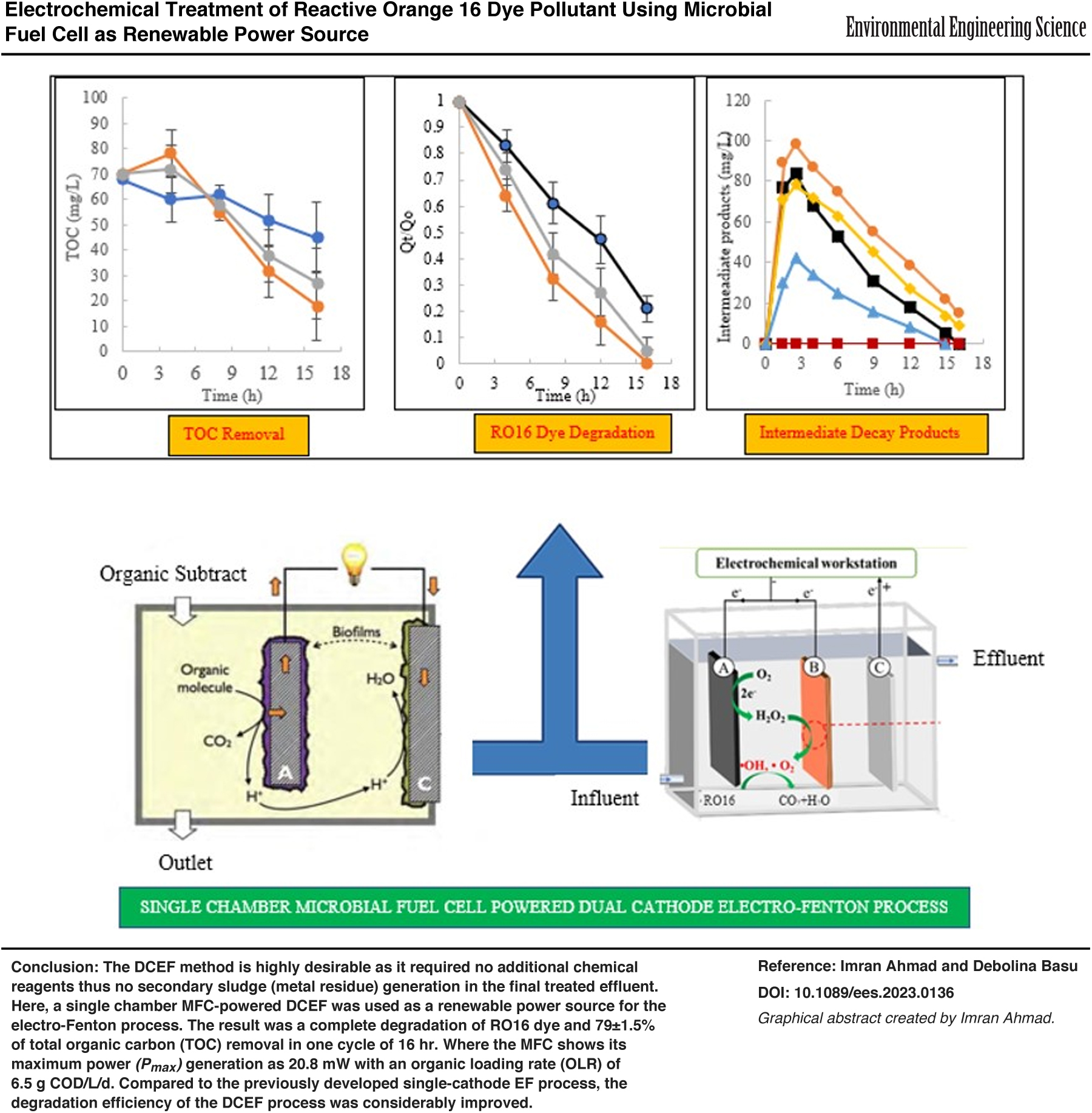
Electro-Fenton (EF) process plays an effective role for organic pollutant degradation, although it required nonsustainable electrical power source to produce hydrogen peroxide (H2O2). Two-chamber microbial fuel cells (MFCs) have been proposed for pollutant treatment using Fenton-based reactions, but these MFCs generate low-power densities and required expensive membranes. Here, we proposed a more efficient dual-reactor system with single-chamber MFC as renewable power source for dual cathodes electro-Fenton (DCEF) process treatment of reactive orange 16 (RO16) dye as model pollutant. The MFC was fabricated with a low-cost earthen pot (volume = 750 mL) using a carbon felt anode and carbon cloth air cathode, respectively. For the DCEF chamber, two cathodes: graphite plate (C1) and stainless steel (C2) were used for simultaneous H2O2 production and activation. The MFC produced the maximum power (Pmax) of 20.8 mW at an organic loading rate (OLR) of 6.5 g COD/L/day. For any higher OLR ≥6.5 g COD/L/day, the MFC shows an overloaded organic substrate condition which resulted in a reduction in system efficiency. It was found that complete degradation of RO16 dye and 79 ± 1.5% of total organic carbon removal was achieved in one cycle (16 h) of the dual reactor system. Compared to the previously developed single-cathode EF process, the degradation efficiency of the DCEF process was considerably improved. The results of the developed dual-reactor system show efficient removal of RO16 persistent organic pollutants that would advance the practical application of the EF treatment process.
Introduction
Increment in energy consumption causes great stress on available natural resources and toxic emissions to the environment and aquatic bodies. To handle the problem, application of the environmentally friendly alternatives has been significantly developed over the last few decades. These alternative sources utilized the energy more effectively, ecologically, and with energy-saving technologies. One of the most frequently used technology is the microbial fuel cell (MFC). The MFC technology works as an electrochemical system and uses electrogenic bacteria present in wastewater to convert biodegradable organic waste into electrical energy (Ilamathi and Jayapriya, 2018; Solanki et al., 2013).
In the working mechanism of the MFC, the exo-electrogen bacteria present in the wastewater solution, anaerobically oxidize biodegradable organics subtract (sucrose) to release electrons at the anode and protons to the solution. With external circuit application, the generated electrons reached the cathodic chamber, whereas an equivalent proton reached the cathode through the cation exchange membrane (Ilamathi and Jayapriya, 2018; Solanki et al., 2013). Thus, with the help of exo-electrogen bacteria as biocatalysts, MFC converts organic chemical energy into electrical energy.
The following Equations (1) and (2) illustrate the normal half-cell reaction potentials at the electrode surface of the MFC with terminal electron acceptor source as atmospheric oxygen.
In the practical application of the MFC, the methanogenesis process poses a great obstacle. Due to similar growth conditions and competitive nature with the exo-electrogen, the methanogenic microbes utilized the electrons from the anodic substrate, resulting in the reduction of MFC coulombic efficiency (Rajesh et al., 2015; Tice and Kim, 2014). Therefore, limiting or stopping the methanogenesis activity is essential for electrogenic microbial growth. It will ultimately cut the anodic substrate intakes and coulombic losses (More and Ghangrekar, 2010; de Dios et al., 2014).
Several studies have been conducted for methanogenesis suppression such as keeping the sludge inoculum under stress conditions with low pH and varied operational temperature or external resistance conditions, and others (Chae et al., 2010; Jung and Regan, 2011; Rismani-Yazdi et al., 2013). Since the methanogenic microbes survive under anaerobic conditions, oxygen supply to the MFC operation will definitely control the methanogenic activity (Tice and Kim, 2014). Chae et al. (2010) work on MFC operation for the possible impact of air exposure with anodic media air exposure, aeration, and submergence in an oxygen-rich medium, concluded that air stress to the inoculum sludge can be used as a simple and affordable way for suppressing methanogenesis activity.
For dual-chamber MFC applications, the power output capacity is found usually low because of the high internal membrane resistance and thermodynamic restrictions at various parts. These flaws of dual-chamber MFC cause higher potential losses (ohmic loss, activation loss, mass transfer loss, etc.) as compared to air cathode single-chamber MFC. Also, the used membrane gets fouled with time which is also an additional drawback of the dual-chamber MFC chamber. Therefore, the two-chambered MFC does not seem to be a feasible solution for persistent organic pollutant (POP) treatment, and single-chamber MFC was generally preferred.
The sulfonated reactive azo dyes are available in a wide range of colors and categories in the global market. Reactive orange 16 (RO16) is one of the most commonly used dyes in the textile industry. It has one or more sensitive atoms that allow it to react with amino acid functional groups and cellulose hydroxyl of synthetic fabrics (Zhang et al., 2022; Zhou et al., 2021). It is frequently employed in textile dyeing procedures for dyeing cotton, wool, viscose fiber, silk, leather, and nylon. However, due to the lower rate of dye-fiber fixation, a major portion of dyes (≥70%) are discharged to waterbodies as unused (Jia et al., 2019; Mubbashar et al., 2022; Tan et al., 2022). The presence of the azo bonds (-N = N-) in these dye pollutants causes a major resistance in degradation by the traditional treatment methods (Jiang et al., 2021; Kecić et al., 2018; Yang et al., 2019; Zakaria et al., 2019; Zha et al., 2021).
Worldwide several traditional and advanced treatment methods have been used for POP treatments. The conventional methods include biological (e.g., sequential batch reactors technology, trickling filter), physical (e.g., coagulation, adsorption), and chemical process (e.g., oxidation, coagulation, chemical precipitation, ion exchange process) (Crini and Lichtfouse, 2019; Katheresan et al., 2018). However, these methods have several limitations. Biological treatment methods take a long time for their full process completion and are unable to decompose nonbiodegradable compounds, also very sensitive to toxic influents (Marquez et al., 2015). Physical methods need further treatment that raises the overall cost and also is less desirable because of the possibilities of the undecomposed contaminants transfer among the different phases of the treatment. Chemical treatment requires high operational costs due to huge quantity of chemicals requirement (Hung, 2009).
Also, treatment using membranes (microfiltration, ultrafiltration, nanofiltration, and reverse osmosis) has widely been used for wastewater treatment because of their applicability and benefits of low installation and operational costs (Akdemir and Ozer, 2009; Cassano et al., 2011; Coskun et al., 2010; Garcia-Castello et al., 2010). However, a common problem for this technology is membrane fouling that strongly reduces the flux of permeates that change the membrane selectivity. Additionally, fouling issues make the process highly expensive due to repeated plant shutdowns for cleaning and washing the membranes (Cassano et al., 2011).
In the past few years, the electro-Fenton (EF) electrochemical advanced oxidation process has received lots of interest for various POPs treatment (Gang et al., 2023; Ahmad and Basu, 2022a; Martins et al., 2010; Masomboon et al., 2011). It used the in-site generated hydroxyl radical (•OH) that acts as a powerful oxidizing agent and reacts in an unselective way to degrade the pollutants into simple molecular products [Eqs. (3)–(5)] (Ahmad and Basu, 2022b; Zhang et al., 2007; Zhou et al., 2012). Studies have shown that hydrogen peroxide (H2O2) can be electrocatalytically activated on nonsacrificial cathodes to produce •OH (Imamura et al., 2010; Weng et al., 2020). Therefore, it is theoretically possible to transform oxygen to H2O2 and subsequently •OH through two cathodic reactions for simultaneous H2O2 production and activation [Eqs. (3) and (4)]. Such a method is highly desirable as it requires no additional chemical reagents; thus, no secondary sludge (metal residue) generation.
Various recent experimental works on different types (phenols, antibiotics, rhodamine B) of persistent nature pollutants have shown the effectiveness of this dual cathodes electro-Fenton (DCEF) process treatment (Jiabei et al., 2021; Su et al., 2020; Tang et al., 2021).
In this study, we used a dual-cathode-modified EF system to overcome the limitations of conventional EF systems of external iron catalyst (Fe+2/Fe+3) requirement and secondary iron sludge generation. A single-chamber MFC was used to drive H2O2 in a second dual-cathode electrochemical reactor. The dual cathode (graphite plate and stainless steel) of the EF chamber simultaneously produces and activates the H2O2 for •OH production. Here, we used the dual-cathodes Fenton cell for RO16 model azo dye treatment. We believe that the study will provide a more energy and cost-efficient POP treatment that would advance the practical application of the conventional single-cathode EF treatment process.
Materials and Methods
Single-chambered MFC-powered DCEF cell
The schematic diagram of dual-cathode modified EF system powered by single-chamber MFC has shown in Fig. 1. For MFC fabrication, an earthen pot (volume = 750 mL; internal diameter = 14 cm) was used serving as the anodic chamber. This earthen pot anode was kept inside glass bucket that acted as cathode chamber with aerated water serving as both (i) catholyte; and (ii) methanogenesis activity suppression (airflow rate = 1.2 L/h) (Raychaudhuri and Behera, 2020). The earthen pot wall (thickness = 4 mm) worked as the separator as well as the cation exchange membrane between the anodic and cathodic chambers (Behera et al., 2010).

The single-chamber MFC-powered dual cathodes electro-Fenton system: Lab-setup and schematic diagram (A: graphite plate, B: stainless-steel, C: stainless-steel). MFC, microbial fuel cell.
In MFC, carbon felt (projected surface area = 192 cm2) and carbon cloth (projected surface area = 260 cm2) were used as an anode and cathode, respectively. Anaerobic sludge was taken from the bottom of a up-flow anaerobic sludge blanket tank (characteristics listed in Supplementary Table S1) for anodic inoculum of MFC and operated with an external resistance of 1,000 Ω at room temperature. The synthetic wastewater composition was prepared as per the Jadhav and Ghangrekar (2009) work with sucrose as the source of carbon (Supplementary Table S2). The voltages across the external resistors were recorded using a multimeter (model: EX355-ND; FLIR Ex-Tech).
The modified dual cathode EF reactor was constructed using 600 mL capacity rectangular plexiglass (size = 6 cm × 10 cm × 10 cm). The stainless-steel plate anode (5 cm × 4 cm) of the DCEF chamber was connected to the MFC cathode and the other two cathodes (A: graphite plate and B: stainless-steel) with anode plate of MFC using copper wire. Graphite plate cathode (5 cm × 4 cm) was used as an additional cathode in the study because previous studies (Kuleyin et al., 2021; Nidheesh et al., 2014) have demonstrated that oxygen can be effectively reduced to H2O2 using graphite material with also relatively inexpensive. The mutual spacing between the anode and the cathode was kept at 2 cm (Zhou et al., 2012). The solution pH was adjusted to 3.5, 5.0, or 7.0 using 0.2 M sulfuric acid and 0.2 M sodium hydroxide. The phosphate buffer was used to avoid significant changes in pH during the experiments.
Electrical power analysis
Using a multimeter, MFC cell voltage (U) and electrode potentials of the DCEF system were recorded with Ag/AgCl as the reference electrode (+197 mV vs. standard hydrogen electrode). Resistor box (Nortonkit NKIT, Wood Resistance Box) was used between the MFC anode and the DCEF cathodes to conduct polarization test (resistance variation from 5,000 to 0 Ω) (Fig. 1). At the time of polarization, all the potentials were noted with a reference electrode (Ag/AgCl). With Equation (6), the MFC power output (P) was calculated as
where U and I are cell voltage (V) and produce current (A) of MFC, measured with digital multimeter.
Chemical analysis
A high-performance liquid chromatography (HPLC; Shimadzu LC-20AT) equipped with an Allure® Organic Acids 5 μm column and a diode array detector at wavelength (λ = 210 nm) was used for quantification and degradation intermediates of RO16 azo dye. The mobile phase was 50 mM monopotassium phosphate (KH2PO4) buffer which was used at flow rate of 1.0 mL/min. For the total organic carbon (TOC) analysis, the Shimadzu TOC-VCSN Total Organic Carbon analyzer was used.
With the application of the N,N-dimethyl-p-nitroso-aniline (RNO) spin trapper, •OH were quantified (Comninellis, 1994; Zhu et al., 2008). For each test, 70 mL of a 60 mM KH2PO4 buffer solution with 210 μM RNO was introduced to the DCEF cell, and yellow color lightening was measured with a spectrophotometer (QLUV2100; Quicklab, China) at λmax = 440 nm. In the study, the •OH concentrations were quantified at three pH levels 3.5, 5.0, and 7.0 as 218 ± 8, 176 ± 15, and 46 ± 12 μM, respectively. For pH = 3.5, the largest value for •OH was estimated (Supplementary Fig. S1). This pH value was also compatible with the MFC optimal power output (Li et al., 2013; Zhu and Logan, 2013), and anticipated as the most favorable operational pH for the EF process (El-Ghenymy et al., 2012; Panizza and Cerisola, 2009; Pignatello et al., 2006).
MFC biofilm developed electrodes
The scanning electron microscope (SEM; TESCAN MIRA3 LMH) test was performed for the bacterial growth study on MFC electrode surfaces. Samples were fixed overnight in 2.8% paraformaldehyde, 1.8% glutaraldehyde, and rinsed five times in 0.2 M cacodylate buffer (pH 7.4) at 3°C, and then dehydrated gradually in a graduated series of water/ethanol solutions (20%, 40%, 60%, 75%, 80%, 90%, 95%, and 100%) (Liu and Logan, 2004). Finally, the mixture was dried at a critical CO2 temperature (31.1°C). Before the SEM test, the samples were sputter-coated with gold.
The carbon cloth cathode appeared to have a number of carbon wires (diameter of 10 to 20 μm), where biofilms were formed on both the electrode surfaces. Compared to the undeveloped carbon cloth electrode, the conductive film of the microbial-developed carbon cloth possessed much rougher surfaces. Numerous bacteria developed on the carbon-felt anode, and its morphology seemed to be rather homogeneous (Miron et al., 2019). However, a considerably more diverse biofilm was observed to have developed on the cathode surface. The formation of the microbial layer on the electrode surfaces significantly increased the surface areas (Ghangrekar and Shinde, 2007). This suggested that the surfaces produced by microbes would provide more active centers on the electrode for electrocatalytic and bioelectrocatalytic activity.
Results and Discussions
Electrical performance of single-chamber MFC system
At the beginning of the MFC, negligible operating voltage was seen that gradually increased with time. After successive feeding of three cycles (15 days each), a stable voltage was found, confirming that the exo-electrogenic microbial consortia activated after a lag phase (Dattatraya et al., 2017).
The MFC was then used as a power source for the EF reactors to degrade RO16 dye in solution. After 45 days of operation, polarization test was conducted at different organic loading rates (OLRs) of 0.50, 2.0, 4.5, and 6.5 g COD/L/day. The corresponding peak currents (Imax) were measured as 16, 18, 25, and 33 mA, respectively (Fig. 2A), suggesting that Imax has a linear relationship with OLRs. An increment in OLR causes accretion in the rate of the reactions that ultimately enhance the current generation (Sharma and Li, 2010). At a maximum OLR of 6.5 g COD/L/day, the extracellular electron transfer reached its optimum rate which resulted the maximum current generation (Jadhav et al., 2015). However, for a further increment of the OLR ≥6.5 g COD/L/day, current drop was observed (from 33 to 18 mA). The reason for this drop of biocatalytically generated current could be the restricted utilization of the organic subtracts (Sharma and Li, 2010).
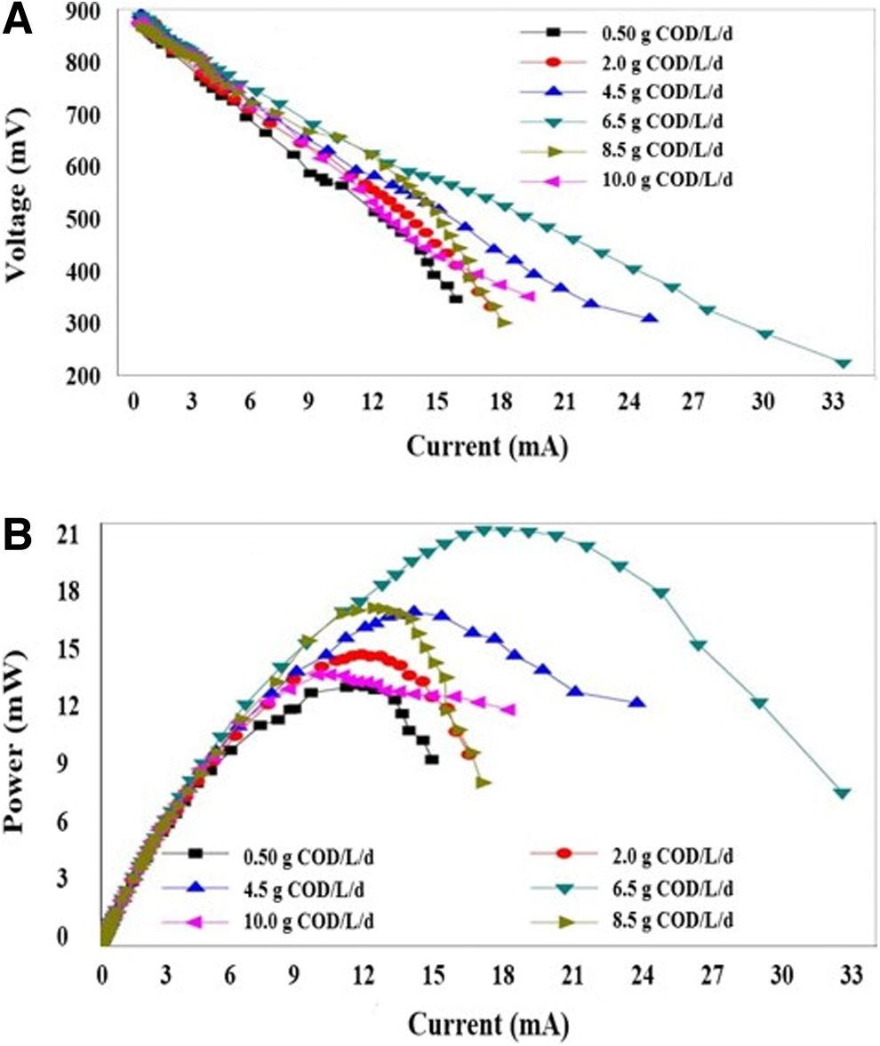
The MFC:
With forward polarization and a constant external resistance (Rext) of 1,000 Ω, varying OLRs of 0.50, 2.0, and 4.5 g COD/L/day resulted in the maximum power (Pmax) generation as 11.80, 12.38, and 15.14 mW (Fig. 2B). For OLR increment from 4.5 to 6.5 g COD/L/day, a marked rise in Pmax was observed up to 20.8 mW. For further increase of OLR ≥6.5 g COD/L/day, the Pmax was significantly reduced. For OLR of 10.0 g COD/L/day, a sharp fall in power (12.3 mW) was observed that attributed to the restricted organic subtract utilization due to overloaded condition (He et al., 2015).
Organic overloading
In the MFC system, the organic subtracts were used for electricity generation through the volatile fatty acids (VFAs) generation and oxidation process with the help of the fermentative and electrochemically active bacteria, respectively (Supplementary Fig. S2). Organic subtracts overloading caused the system imbalance. At higher OLRs, the VFA accumulation decreases, resulting in the washout of the electrochemically active bacteria. Also, the microbial consortium with a wider diversity particularly the filamentous bacteria with the preventing rod shape was reported at overloaded organic subtracts condition (Aelterman et al., 2003; Xing et al., 2009). These filamentous bacteria cause the blockage of the electrode surface and inhibit biofilm regeneration (Lin et al., 2004).
Therefore, organic overloading conditions disrupted the distribution balance of microbial consortia, which further hampered substrate conversion and promoted the build-up of VFAs. Also, overloaded organic subtracts condition exceeds the capacity of methanogens, that considered a form of system imbalance for anaerobic digestion and negatively affects the anaerobic fermentation causing a washout of microbes (Liu et al., 2004). In the study performed by He et al. (2015), the VFAs accumulation was observed at ORL ≥6.97 g COD/L/day, with a sudden increment for the higher value of 10.27 g COD/L/day that significantly dropped the power generation. A similar result was also seen by Nam et al. (2010)'s work, where the power drop started at ORL ≥4.80 g COD/L/day.
Electrochemical impedance spectroscopy
To further study the effect of OLR concentration on MFC internal resistance, different components of internal resistance were estimated from the electrochemical impedance spectroscopy (EIS) test. The EIS test of the MFC can be represented in terms of an equivalent electrical circuit that comprises a combination of resistances and capacitances at lower to higher frequency ranges (Fig. 3) (He and Mansfeld, 2009). With the increment in OLR from 0.5 to 6.5 g COD/L/day, the conductivity of the solution and rate of bacterial anode electron transfer increases which caused a reduction in internal resistance (solution resistance, RS; and polarization resistance, RA). However, a considerable rise in RA was observed when OLR rose from 6.5 to 10 g COD/L/day, with a slight change in RS value. The formation of inactive biofilm for the electrochemical reactions, with an increment with OLRs, was the prime cause for this rise in Rs and RA; as at higher OLRs, the inactive biofilm caused the greater resistance for substrate utilization (He et al., 2015).
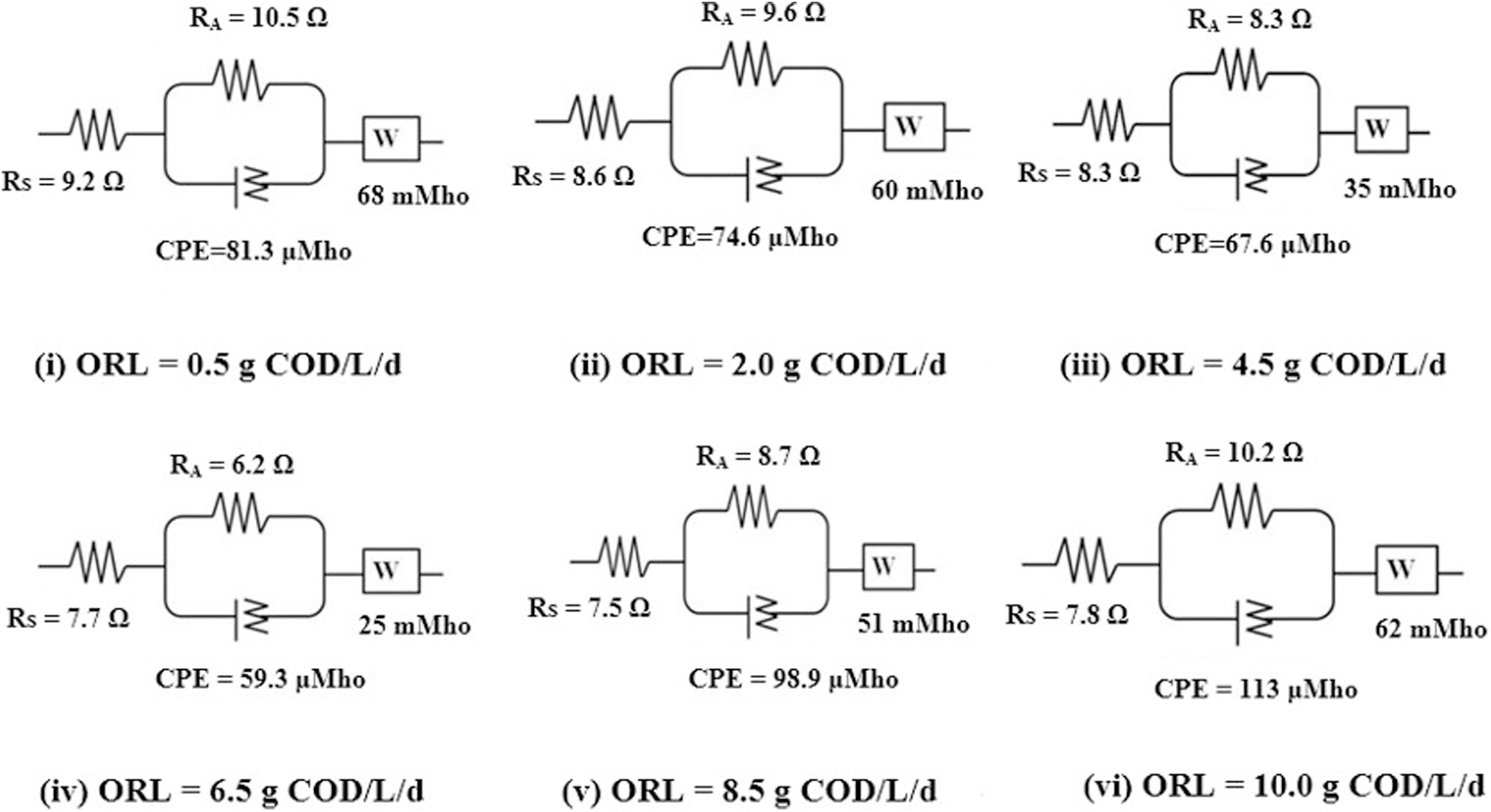
Equivalent circuit for MFC.
When organic subtract was present in lower concentrations (OLR = 1.5 g COD/L/day), the organic subtract has the high impedance in low- to mid-frequency range due to slower oxidation process. For an increment up to 6.5 g COD/L/day of OLR, anodic biofilm had a favorable impact on the kinetics of the bioelectrochemical interaction and activation losses (RAC) (Sanchez-Herrera et al., 2014). Although, with each further increase in OLR (≥6.5 g COD/L/day) up to 10 g COD/L/day, the inhibitory effect of the accumulating intermediate product of fermentation increased the impedance that reduced the kinetics of anodic reactions (Sanchez-Herrera et al., 2014).
At greater OLR, the corresponding circuit shows a rise in Warburg's diffusion resistance (W). Mass transport loss may also increase with rise in OLR that resulted in the substrate diffusion restriction via the thicker biofilm, with a detrimental effect on the anode biocatalytic activity (He et al., 2015). Due to nonuniform condition, the constant phase element (CPE) replaces the capacitance in the equivalent circuit (He and Mansfeld, 2009). At low frequencies, CPE decreased with rising OLR, as seen from the fitted equivalent circuit (Fig. 3). The capacitance at high frequencies was associated with charge transfer and interfacial charge accumulation, which was clearly separated from the low-frequency diffusion process by CPE. Therefore, the electrochemical analysis confirms that an increase in OLR up to an optimal value of 6.5 g COD/L/day caused an increase in bioelectrochemical reaction rate and decrease in internal resistance.
RO16 degradation and stability
At steady power generation for the MFC, the dual reactors system was run at three OLRs of 4.5, 6.5, and 8.5 g COD/L/day. The concentrations of RO16 and TOC were monitored over time during a fed-batch cycle (16 h). For the OLR condition of 6.5 g COD/L/day, it was found that total RO16 dye and TOC up to 79% were removed (Fig. 4).
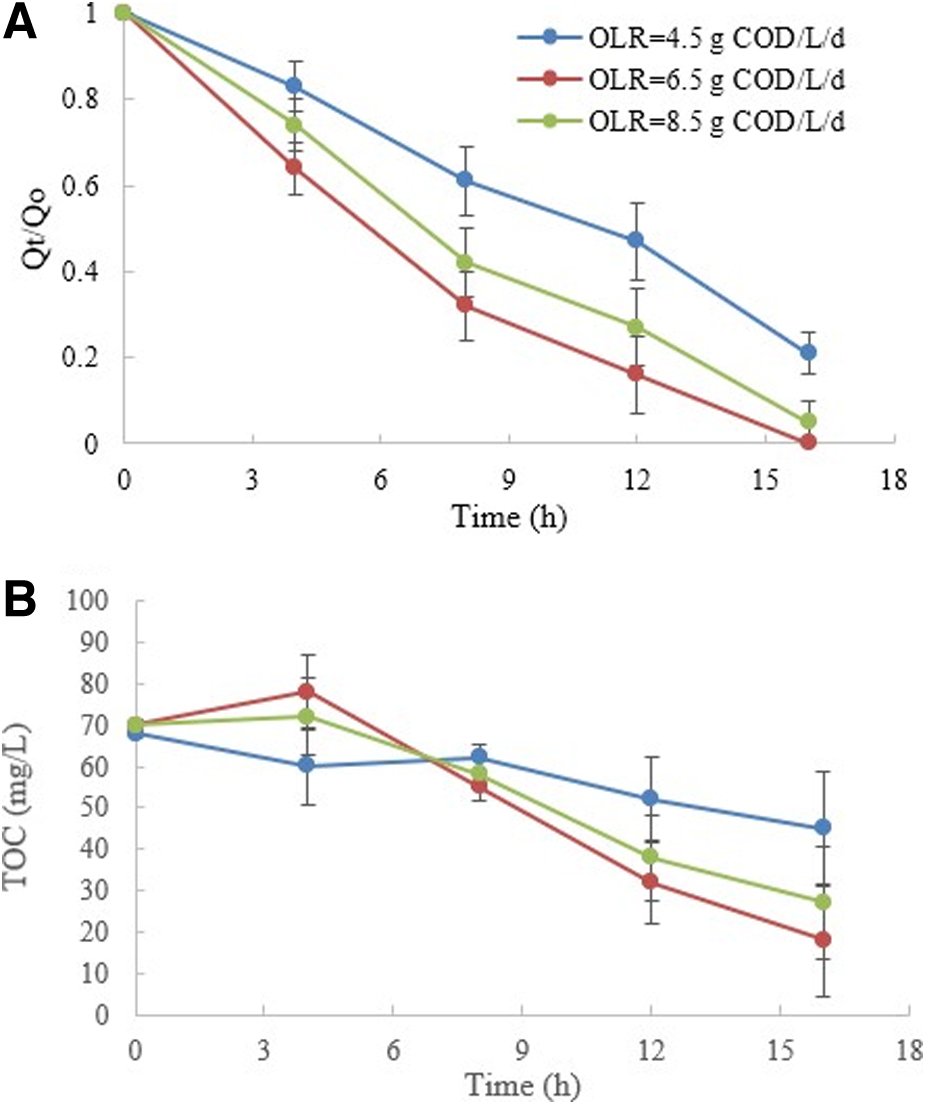
For the stability check of the developed dual-reactor system, experiments were carried out in five consecutive cycles. Each time MFCs were replenished with a new medium, and the DCEF reactor was rinsed with distilled water, which was again refilled with RO16 dye solutions. For a total treatment of 12 h, the RO16 removals were maintained as 90% (OLR = 6.5 g COD/L/day), 82% (OLR = 8.5 g COD/L/day), and 55% (OLR = 4.5 g COD/L/day) (Fig. 5A), whereas a larger variability was seen for TOC removals during the cycles (Fig. 5B). These variations could be partly a consequence of the measurement method. The low TOC of the dilution water (0.2–0.5 mg/L) and dissolved CO2 may be a bigger contributor for this variation in the predicted TOC changes since samples were highly diluted (10 times) to assess TOC concentrations in the instrument range (0 to 10 mg/L).

UV-spectrophotometry test
The UV-spectrophotometric test was done for confirmation of the final mineralization of the dye and intermediate products obtained from the DCEF process (Supplementary Fig. S3). The standard RO16 dye solution showed two peaks in the visible range (at λ = 493 and 398 nm) and two peaks in the ultraviolet range (at λ = 256 and 299 nm). The visible range peaks correspond to the aromatic structure of RO16 dye, whereas the UV range represents the conjugated (extended chromophores) azo bond structure (Padmanaban et al., 2018). At optimum conditions of the dual-reactor system (OLR = 6.5 g COD/L/day, pH = 3.5), the synthetic dye solution lost its color after 16 h of treatment. In the UV spectrophotometry, this was observed by the disappearance of prominent peaks without the appearance of any interference peaks that might be caused by intermediates products formed during the degradation process. Also, the oxidation breakdown of the aromatic rings and their intermediate products were further confirmed by disappearance of visible and UV range peaks, showing complete removal of the RO16 dye in the effluent solution (Wu et al., 2015).
Intermediate decay pathway
For the MFC-powered DCEF operation, monitoring of the intermediate products was done at OLRs of 4.5, 6.5, and 8.5 g COD/L/day. For the OLR of 6.5 g COD/L/day, the degradation rate was higher due to more electricity generation that resulted in more intermediate products generation as compared to other two OLRs (Fig. 6). In the generated intermediates, the hydroquinone (C6H6O2), fumaric acid (C4H4O4), maleic acid (C4H6O5), oxalic acid (C2H2O4), and formic acid (CH2O2) were the five primary VFAs. As per the carbon balance study, it was found that almost 90% of the RO16 dye had been converted to intermediate products after 3 h of treatment, which confirms the significant role of the dual cathodes for the Fenton reactions in the RO16 dye degradation.

Various intermediates volatile fatty acids formed during the RO16 dye degradation at different OLRs:
The remaining 10% degradation of the RO16 dye was most likely caused by indirect oxidation due to the presence of chloride (Cl−) ions generated from electrolyte (sodium chloride) that favor the mediated oxidation with active chlorine [Cl2, hypochlorous acid (ClOH)] (Alagesan et al., 2021; Hakizimana et al., 2017) [Eqs. (7) and (8)].
The complex intermediates (C6H6O2, C4H4O4, and C4H6O5) successively reduced to simple carboxylic acids (-COOH) before the final degradation of the CO2 and H2O products. It was found that simple carboxylic acids with lower molecular weight such as C2H2O and CH2O2 remained in the effluent even after the cycle completion (16 h). The final product compounds of the used DCEF process were also comparable with other RO16 dye treatment methods such as ozonation, electrochemical oxidation, and photocatalysis (Canizares et al., 2005; Emilio et al., 2006; Li et al., 2005).
Conclusions
Two-chamber dual cathodes EF system powered by single-chamber MFC as renewable power source has shown to be an effective method for RO16 dye degradation under acidic conditions (pH = 3.5). For the single-chamber MFC, the best performance was observed at OLR of 6.5 g COD/L/day, and an airflow rate of 1.2 L/min with maximum (Pmax) generation as 20.8 mW/m2. For any higher OLR ≥6.5 g COD/L/day, the MFC shows an overloaded organic substrate condition which significantly reduces the process efficiency. At higher OLR (≥6.5 g COD/L/day), the EIS test confirms the formation of inactive biofilm at the anodic surface of MFC which caused greater substrate utilization resistance.
For the developed dual-reactor system, RO16 dye was completely degraded to simple organic acids (C2H2O4 and CH2O2), and a total of 79% TOC was removed after one cycle of 16 h. The HPLC analysis shows C6H6O2, C4H4O4, C4H6O5, C2H2O4, and CH2O2 as the main intermediate products. Compared to previous EF systems with single cathode application, the dual-cathode single-chamber MFC-powered system showed substantially improved degradation efficiency for RO16 dye pollutant, which significantly reduces the operation cost because of the elimination of iron catalyst requirement and no secondary iron sludge generation. The results of the developed dual-reactor system show efficient removal of RO16 dye pollutants that would advance the practical application of the EF treatment process for POPs treatment.
Footnotes
References
Supplementary Material
Please find the following supplemental material available below.
For Open Access articles published under a Creative Commons License, all supplemental material carries the same license as the article it is associated with.
For non-Open Access articles published, all supplemental material carries a non-exclusive license, and permission requests for re-use of supplemental material or any part of supplemental material shall be sent directly to the copyright owner as specified in the copyright notice associated with the article.