
Abstract
The term ‘scallop form’ is used to refer to a structural form, such as a dome, that has ‘arched’ sectors. Thus, in addition to the general ‘curviance’ of the dome, the sectors are separately arched. The term ‘curviance’ means ‘the way a form is curved’. Also, the term ‘scallop’ refers to the marine creature scallop whose shell has arched ribs. Scallop forms constitute a wide range of spatial structural forms that can provide efficient structural solutions. The form processing programming language ‘Formian’ includes capabilities that allow the geometry of various types of scallop domes to be generated conveniently (visit Formexia.com). Also, the new version of the language, namely, Formian-K has extended the scalloping facilities of the language to include scallop barrel vaults. The objective of this article is to explore the range of possible scallop forms and to explain how these forms may be generated using the ‘scalloping functions’ of the Formian language. This article contains many practical examples, in terms of which the generation of forms is discussed. This article is meant to be a practical manual for generation of scallop forms. However, to understand all the details of the operations, it is expected that the article is studied together with the necessary background material.
Keywords
Background
A thorough study of the geometry of scallop domes and vaults was carried out in the early 1990s in the Space Structures Research Centre of the University of Surrey, UK. The results are recorded in an MPhil Thesis. 1 Subsequently, a paper describing the basic geometric particulars of scallop domes was published in a conference in Singapore. 2 This 1997 paper that henceforth will be referred to as the ‘Singapore paper’ is a basic source of information for this article.
In this article, the form processing programming language Formian will be used as the medium for the processing of scallop forms. A basic source of information on the Formian language is Nooshin and Disney. 3 This source consists of three chapters in a book. These three chapters provide an introduction to the ideas of ‘formex configuration processing’ and the ‘programming language Formian’. To refer to this material in this article, the abbreviation ‘FPC’ is used (standing for Formex Configuration Processing).
Another major source of information on Formian and its theoretical basis, namely, formex algebra, is the website ‘Formexia.com’.
Scalloping a dome
Consider the dome with a ‘lamella’ pattern and a spherical curviance shown in Figure 1. The term ‘curviance’ is discussed in the study by Nooshin and Samavati. 4 The term ‘lamella pattern’ is synonymous with ‘diagonal pattern’.

A spherical lamella dome.
The dome of Figure 1 has been generated using the Formian formulation shown below:
(*) Scheme 1: Lamella dome of Figure 1 (*) (*) Setting parameters (*) S = 30; (*) Span in metres (*) H = 5; (*) Rise in metres (*) m = 36; (*) Frequency of crosses in U2 direction, this parameter must have an even value (*) n = 5; (*) Frequency of crosses in U3 direction (*) A = 2*atan|(2*H/S); (*) Sweep angle (*) R = S/(2*sin|A); (*) Radius of circumsphere (*) (*) Generating the geometry of the dome in spherical normat coordinates (*) E = rinit(m,n-2,2,2)|lamit(1,6)|[1,0,5; 1,1,6]# rinit(m,2,2,2*(n-2))|[1,0,5; 1,2,5]#rinit(m/2,2,4,2)| lamit(2,2)|[1,0,1; 1,2,2]#rin(2,m/2,4)| {[1,2,5;1,2,4], [1,0,1;1,0,0]}; (*) Transferring to Cartesian coordinates (*) b1 = R; b2 = 360/(2*m); b3 = A/(2*n + 1); F = bs(b1,b2,b3)|E; (*) Setting viewing particulars and drawing (*) use &,vm(2),vt(2),vh(0,R,2*R, 0,0,0, 0,0,1); clear; draw F; <>
The above programme is called ‘Scheme 1’, where the term ‘scheme’ is often used in Formian to imply a piece of formulation. The writings in Scheme 1 that are enclosed between symbols ‘(*)’ are comments describing the purpose of each part of the formulation. Detailed explanations regarding the meanings and effects of the instructions in Scheme 1 are found in FCP, sections 1.1 to 1.9. The colour codes used in the scheme are as follows: ‘green’ for comments, ‘blue’ for keywords and function imprints (names), ‘red’ for diamer (scheme separator) and ‘purple’ for other objects.
Sectoral division of a dome
In order to subject a dome to the scalloping process, it is necessary to specify the required number of ‘sectors’. For example, Figure 2 shows four different ways of ‘sectoral division’ for scalloping of the dome of Figure 1. The scallop dome of Figure 2(a) has six sectors, where each sector has a central angle of 60° in plan. This central angle is referred to as the ‘sectoral angle’ and is denoted by ‘As’. Figure 2(b) shows the dome of Figure 1 scalloped into nine sectors with a sectoral angle of 40°. Also, Figure 2(c) and (d) have three and four sectors with As = 120° and As = 90°, respectively.

Scalloping with different number of sectors.
Options for the forms of scalloped sectors
The conceptual tool for transforming a dome like the one in Figure 1 into those in Figure 2 is a Formian function called the ‘scallop basispherical function’ (abbreviated to ‘sbs function’). This function needs a number of specifications to be made by the User. Included in these is the specification of the sectoral angle. However, before discussing the ‘sbs function’, it is necessary to consider some other required specifications, which mainly concern the curviance of the scalloped sectors.
These specifications are made using the directions shown in Figure 3. To elaborate, the first direction, denoted by U1, is the ‘radial direction’ that passes through the centre of the circumsphere of the dome (circumsphere of a dome is the sphere that contains all the nodes of the dome). The second direction, denoted by U2, is the ‘circumferential direction’ corresponding to the ‘parallels’ on the circumsphere of the dome (with the ‘north pole’ being at the crown of the dome). The third direction is the ‘meridional direction’, denoted by U3. This direction corresponds to the ‘meridians’ on the surface of the circumsphere of the dome. These three directions, which correspond to a ‘spherical coordinate system’, are suitable for the specification of the scalloped forms of the sectors.

Spherical coordinate directions for the specification of the scalloped forms of sectors.
Formian allows two styles of arching (curving) of the sectors in the U2 (circumferential) direction. To be specific, the arching can be either ‘parabolic’ or ‘sinusoidal’. The parabolic variation in the U2 direction is exemplified in Figure 4(a). Also, an example of sinusoidal variation in the U2 direction is illustrated in Figure 4(b). Further information about the parabolic and sinusoidal curving of the sectors in the U2 direction is given in the Singapore paper, section 3.

Various options for the forms of scalloped sectors: (a) Mode 1, (b) Mode 2, (c) Mode 3, and (d) Mode 4.
It is important to note that the meridians on the sides of the sectors always keep their original forms and remain unaffected by the curving of the sectors.
In addition to the style of curving, it is necessary to specify the magnitudes of ‘movements’ for curving of the sectors. Two components of movement should be specified, namely, the vertical and horizontal movements of a midpoint of a sector. The vertical component of the movement is referred to as the ‘amplitude’ and the horizontal component is referred to as the ‘prominence’, as shown in Figure 4.
It is also necessary to specify the point at which the amplitude and prominence are specified. This point is specified by its U1 (radial) and U3 (meridional) coordinates. The circumferential coordinate U2 is not necessary, since the point is assumed to be at a midpoint of a sector. The point of the specification of the amplitude and prominence in Figure 4 is indicated using the letter ‘S’.
It should be emphasised that the scalloping process fundamentally concerns the ‘curviance’ rather than the ‘pattern’ of a configuration. To elaborate, it is the ‘surface’ that is curved (arched) and the ‘pattern’ simply follows the surface. Despite this, there are certain considerations that involve the pattern, as will be discussed later. However, at this stage, since the scalloping specifications only relate to the curviance, Figures 3 and 4 are shown without any pattern (see Nooshin and Samavati 4 regarding the relationship between curviance and pattern).
The next required specification concerns the manner of variation of the amplitude and prominence along a meridian. In this regard, the position of the central point (crown) of the dome remains unaffected. Also, the magnitudes of the amplitude and prominence at the circumferential border points of the dome remain unaffected (these are the points corresponding to the original base ring of the dome). However, the in-between values along a meridian will vary as shown in Figure 5. Here, there are two choices: the variation can be either parabolic or linear. From Figure 5, it can be seen that the linear variation gives rise to higher values of amplitude and prominence, as compared with the parabolic variation. For more detailed information, see the Singapore paper, section 5.

Options for variation of the amplitude or prominence along a meridian.
Finally, the manner of variation of amplitude and prominence with respect to the first (radial) direction should be considered. This variation is straightforward since it is always ‘linear’. To elaborate, as the U1 (radial) coordinate changes then the corresponding amplitude and prominence will change in direct proportion.
The sbs function
The basic Formian function that is used for the generation of scallop domes is called the ‘sbs function’. The name ‘sbs’ is an abbreviation for ‘scallop basispherical’. This function is an extension of the standard Formian function ‘bs’ (basispherical) for generation of spherical domes, as used in ‘Scheme 1’ above, see FCP, section 1.9.
The sbs function is of the form shown in Figure 6, where the name of the sbs is followed by a number of specifications in parentheses. The terms used in Figure 6 are as follows:
‘As’ is the ‘sectoral angle’ (in degrees), as discussed in section ‘Sectoral division of a dome’. This parameter also determines the number of sectors of the dome. Alternatively, if the number of sectors is given by a parameter, say, Nus, then ‘As’ can be given by As = 360/Nus.
‘U1s’ is the first (radial) coordinate of the point of the specification of the amplitude and prominence.
‘U3s’ is the third (meridional) coordinate of the point of the specification of the amplitude and prominence. Here, there is no need for the second (circumferential) coordinate since it is always assumed to be at a mid-sectoral position.
‘Amp’ and ‘Prom’ are the required magnitudes of amplitude and prominence.
‘b1’, ‘b2’ and ‘b3’ are the ‘basifactors’ of the ‘basispherical function (normat)’ used for the formulation of the argument ‘E’, see FCP, section 1.9. An example of the formulation of argument E and the basifactors b1, b2 and b3 is shown in Scheme 1.
‘G’ is the ‘formex variable’ whose value will represent the required scallop dome in Cartesian coordinates.

Constitution of sbs function.
Finally, the term ‘mode’ in Figure 6 has the role of specifying the required styles of variation of amplitude and prominence in U2 (circumferential) and U3 (meridional) directions. The ‘mode’ has four possible options represented by numbers 1, 2, 3 and 4 as follows:
Mode = 1 implies parabolic variations in both U2 and U3 directions, as shown in Figure 4(a).
Mode = 2 implies sinusoidal variation in U2 direction and parabolic variation in U3 direction, as shown in Figure 4(b).
Mode = 3 implies parabolic variation in U2 direction and linear variation in U3 direction, as shown in Figure 4(c).
Mode = 4 implies sinusoidal variation in U2 direction and linear variation in U3 direction, as shown in Figure 4(d).
The application of the sbs function is exemplified in Scheme 2. This scheme is an extension of Scheme 1, where the formulation of the lamella dome of Figure 1 is complemented by instructions to generate various possible scalloped forms of the dome. Among these possibilities are the four scallop domes of Figure 2. Specifically, the values of the parameters in Scheme 2 will produce the scallop dome of Figure 2(a). However, a Formian scheme is, normally, highly ‘generic’ (parametric) and, by changing the values of the parameters, the scheme can generate a wide range of forms.
(*) Scheme 2: Scallop lamella dome of Figure 2(a) (*) (*) Setting parameters (*) S = 30; (*) Span in metres (*) H = 5; (*) Rise in metres (*) m = 36; (*) Frequency of crosses in U2 direction, this parameter must have an even value (*) n = 5; (*) Frequency of crosses in U3 direction (*) mode = 1; (*) Mode of scalloping (*) As = 60; (*) Sectoral angle in degrees (*) U1s = 1; (*) U1 of point of specification (*) U3s = 2*n + 1; (*) U3 of point of specification (*) Amp = 4; (*) Amplitude in metres (*) Prom = 2; (*) Prominence in metres (*) A = 2*atan|(2*H/S); (*) Sweep angle (*) R = S/(2*sin|A); (*) Radius of circumsphere (*) (*) Generating the dome in spherical coordinates (*) E = rinit(m,n-2,2,2)|lamit(1,6)|[1,0,5; 1,1,6]# rinit(m,2,2,2*(n-2))|[1,0,5; 1,2,5]#rinit(m/2,2,4,2)| lamit(2,2)|[1,0,1; 1,2,2]#rin(2,m/2,4)| {[1,2,5;1,2,4], [1,0,1;1,0,0]}; (*) Transferring to Cartesian coordinates (*) b1 = R; b2 = 360/(2*m); b3 = A/(2*n + 1); F = sbs(mode,As,[U1s,U3s,Amp,Prom],b1,b2,b3)|E; (*) Setting viewing particulars and drawing (*) use &,vm(2),vt(2),vh(0,R,2*R, 0,0,0, 0,0,1); clear; draw F; <>
Elaborating on the effects of parameter ‘mode’, if the value of ‘mode’ is changed, from 1 to 2, the execution of the scheme will produce the scallop dome of Figure 7(a). This, of course, relates to the current value of the sectoral angle, that is As = 60°. Now, changing the value of the sectoral angle to As = 120° will result in the scallop dome of Figure 7(b). Also, the scalloped form of Figure 7(c) corresponds to As = 90°.

Some scalloped forms of Figure 1 with sinusoidal variation along the U2 direction.
Figure 8 shows a comparison between scalloped domes with modes 1 and 2 and their corresponding ones with modes 3 and 4. Figure 8(a) has the same particulars as Figure 2(a), namely, Mode = 1, As = 60°, Amp = 4 and Prom = 2. Also, Figure 8(b) has the same particulars, except for the mode which is 3 rather than 1.

Comparison between the scallop domes produced using modes 1 and 3, as well as modes 2 and 4.
Figure 8(a1) shows a side view sketch of the dome of Figure 8(a), and Figure 8(b1) shows a similar side view of the dome of Figure 8(b). It is seen that the scallop domes of Figure 8(a) and (b) are rather similar. However, the difference between them may be clearly noted when their side views in Figure 8(a1) and (b1) are compared. To elaborate, the magnitudes of amplitude and prominence in mode 3 are higher than the corresponding ones in mode 1. This is due to the fact that linear meridional variations (in mode 3) result in higher magnitudes than the parabolic meridional variations (in mode 1), as can be seen in Figure 5. Of course, the positions of the end points, at the base ring and the crown of the dome, for modes 1 and 3 are identical. The difference between modes 1 and 3 occurs at the in-between points.
The comments made regarding the differences between the scallop domes produced in modes 1 and 3 also apply to modes 2 and 4, as shown in Figure 8(c), (c1), (d) and (d1).
Choice of sectoral angle and pattern compatibility
It is to be noted that in all the examples of the scallop domes considered so far, 360° (full circle) is a multiple of the sectoral angles. Indeed, this must be the case for the sectors to fully form and for the sectors to make a full circle.
If 360° is not a multiple of the sectoral angle, then not all the sectors will be fully formed and they will not make a full circle. This is exemplified in Figure 9. Figure 9(a) and (b) represents attempts to scallop the lamella dome of Figure 1 using sectoral angles of 54° and 105°, respectively. Since 360° is a multiple of neither of these two sectoral angles, then there are partly formed sectors and the sectors do not close.

Partial forming and lack of closure of sectors: (a) As = 54° and (b) As = 105°.
The fact that 360° should be a multiple of the sectoral angle is, of course, logical and can be easily understood. The arrangements of the sectors in the domes of Figure 9 are shown in Figure 10, and it is clearly seen that the sectoral angles of 54° and 105° will involve ‘incomplete sectors’.

Arrangements of sectors in the domes of Figure 9.
In addition to the problem of partial formation and lack of closure of the sectors, it is necessary to ensure that the sectoral subdivision is compatible with the pattern of the dome. For example, the sectoral angle of 45° applied to the lamella dome of Figure 1 will result in the configuration shown in Figure 11(a). In this case, there is no problem regarding the partial formation of the sectors and the closure of the dome, because 360° is a multiple of 45°. However, here, there is the problem of lack of compatibility between the sectoral angle of 45° and the pattern of the dome. As a result, the four elements of the base ring, indicated by arrows in Figure 11(a), as well as the four corresponding elements of the middle ring, assume positions outside the surfaces of the scalloped sectors.

An example of the lack of compatibility between the sectoral angle and the pattern of a dome.
Also, in the central region of the dome, the sectoral subdivision does not correspond to the pattern. This can be seen from Figure 11(b), which shows the plan view of the dome of Figure 1, with the ‘scallop valleys’ corresponding to As = 45° shown on it by dotted lines. Here, the dotted line corresponding to every other valley goes out of tune with the pattern in the central region of the dome.
To elaborate further, consider the plan views of the lamella dome of Figure 1 shown in Figure 12. These figures correspond to the scallop domes of Figure 2(a)–(c). Figure 12(a) has six sectors with a sectoral angle of 60°. However, the ‘pattern’ of the dome consists of 18 rotational replications of a 20° sector, as shown in Figure 12(a). This implies that to be compatible with the pattern, the sectoral angle should be a multiple of 20°. This basic angle for a pattern is referred to as the ‘replication angle’ and is denoted by ‘Ar’. So, for the domes of Figure 12, the replication angle is Ar = 20°.

Plan views of the dome of Figure 1, with the sectoral subdivisions corresponding to (a) As = 60°, (b) As = 40° and (c) As = 120°, shown by dotted lines.
Now, since 60° is a multiple of 20°, the sectoral subdivision in Figure 12(a) is compatible with the pattern. Also, since 40° and 120° are multiples of 20°, there are no problems regarding the compatibility of the pattern and the sectoral subdivision in Figure 12(b) and (c). However, since 45° is not a multiple of 20°, the problem of lack of compatibility occurs in relation to Figure 11, as discussed above.
In generating a scallop dome, the compatibility of the pattern with the sectoral subdivision should be considered at the outset. For example, in relation to the dome of Figure 11, if the dome is required to have eight sectors (As = 45°), then 45° should be a multiple of the replication angle Ar. For instance, Ar could be 22.5° and this implies that the parameter ‘m’ in Scheme 2 should be 32 rather than 36. The pattern of the dome will then consist of 16 rotational replications of the generating sector. A scallop dome with these particulars is shown in Figure 13(a). Also, the plan view of the corresponding ‘base dome’ is shown in Figure 13(b), with the ‘scalloping valleys’ indicated by dotted lines. In the case of the scallop dome of Figure 13, there will be no incompatibility problem.

An eight-sector scallop dome with no incompatibility problem.
In section ‘Scalloping a dome’ of this article, all the examples so far have been based on the lamella dome of Figure 1. However, the scalloping concept is also applicable to some other spherical domes. In particular, in addition to all types of lamella domes, there are the families of ‘ribbed domes’ and ‘Schwedler domes’ (see FCP, section 1.9) that can be scalloped using the ‘sbs’ function. Figure 14(a) shows an example of a ‘scallop ribbed dome’, and Figure 14(b) shows an example of a ‘scallop Schwedler dome’.

Examples of (a) scalloped ‘ribbed’ and (b) ‘Schwedler’ domes.
Scalloping a diamatic dome
‘Diamatic domes’ constitute a major family of spherical domes, namely, examples of which are shown in Figure 15. An important feature of diamatic domes is that they do not have the problem of ‘member cluttering’ near the crown.

Examples of diamatic domes: (a) a simple diamatic dome with six sectors, (b) a seven-sector diamatic dome with hexagonal pattern and (c) a five-sector diamatic dome with openings.
To elaborate, domes with ribbed, Schwedler and lamella patterns often suffer from the problem of having too many members near the crown. As a consequence, these domes are often ‘trimmed’ to avoid the ‘cluttering problem’, see FCP, section 1.9. In fact, all the examples of domes used in section ‘Scalloping a dome’ of this article have trimmed configurations. However, as may be seen from the examples of Figure 15, diamatic domes are not affected by the cluttering problem. The term ‘diamatic’ refers to the ‘patterns’ used by these domes. There are many possibilities for diamatic patterns all of which are derived from the basic pattern of Figure 15(a).
The basic formulation, as well as scalloping of diamatic domes, requires special considerations. To see the reason why diamatic domes need special considerations, consider the lamella dome of Figure 16(a) together with the spherical coordinate system U1-U2-U3 (similar to the coordinate system in Figure 3). Note that the lamella pattern follows the meridional curves of the coordinate system (the meridional curves are shown dotted). This compatibility of the meridional curves and the pattern allows the formulation of the pattern to be carried out without any problem.

Comparing lamella and diamatic domes regarding their compatibility with a simple spherical coordinate system.
Now consider a comparable diamatic dome, as shown in Figure 16(b), together with the spherical coordinate system. Here, the side and bottom borders of the pattern in a sector are compatible with the meridional curves. However, the internal elements of the pattern are not compatible with the curves. Therefore, to formulate the geometry of a diamatic dome, a special form of spherical normat (coordinate system) has to be employed, as discussed in detail in FCP, section 2.5.
Based on the approach of FCP, section 2.5, a formulation for the diamatic dome of Figure 15(a) is given below, as ‘Scheme 3’:
(*) Scheme 3: Simple Diamatic Dome of Figure 15(a) (*) (*) Setting parameters (*) S = 40; (*) Span (*) H = 8; (*) Rise (*) m = 8; (*) Frequency (*) n = 6; (*) Number of sectors (*) A = 2*atan|(2*H/S); (*) Sweep angle (*) R = S/(2*sin|A); (*) Radius of circumsphere (*) (*) Generating a sector in diamatic coordinates (*) E = genit(1,m,1,1,0,1)|{[1,0,0; 1,0,1], [1,0,0; 1,1,1], [1,0,1; 1,1,1]}; (*) Transferring to Cartesian coordinates (*) F = bd(R,360/n,A/m)|E; Dome = pex|rosad(0,0,n,360/n)|F; (*) Setting viewing particulars and drawing (*) use &,vm(2),vt(2),vh(R,R,3*R, 0,0,0, 0,0,1); clear; draw Dome; <>
Another important feature of diamatic domes is that they are ‘sectoral’. That is, the pattern of a diamatic dome consists of a number of sectors. This feature makes the diamatic domes ideally suited for scalloping, especially when the ‘scalloping sectors’ are coincident with the ‘diamatic sectors’. For example, using the same scalloping sectors as the diamatic ones, some scalloped versions of the domes of Figure 15 are shown in Figure 17.

Scalloped versions of the examples of Figure 15.
Also, Figure 18 shows an example of a case when the ‘scalloping sectoral angle’, denoted by ‘As’, is not the same as the ‘diamatic sectoral angle’, denoted by ‘Ad’. To elaborate, Figure 18(a) shows a diamatic dome which is the same as the dome of Figure 15(a), except that ever other ring of elements are removed. The removal of these rings is for an important reason that will be explained later.

Scalloping with different sectoral angles: (a) Ad = 60°, (b) Ad = 60°, As = 60°, (c) Ad = 60°, As = 30° and (d) Ad = 60°, As = 30°.
Figure 18(b) shows a scalloped version of the dome of Figure 18(a) with ‘As’ (scalloping sectoral angle) being coincident with ‘Ad’ (diamatic sectoral angle). Figure 18(c) shows a scalloped version of the dome of Figure 18(a) with ‘As’ (scalloping sectoral angle) being half of ‘Ad’ (diamatic sectoral angle).
Finally, Figure 18(d) shows a scalloped version of the dome of 15a with As = Ad/2. The purpose of this figure is to show what would have happed if every other ring of the dome was not removed. The problem with the rings that are removed is that they contain elements that ‘cross the scalloping valleys’. These elements are shown by thick lines in Figure 18(d) and are unacceptable because they are situated outside the surfaces of the sectors.
This problem, together with other points regarding compatibility of patterns for scalloping is discussed in section ‘Choice of sectoral angle and pattern compatibility’. In particular, the case of elements that cross the scalloping valleys is illustrated in Figure 11. In relation to Figure 18, an alternative approach for avoiding the problem would have been to remove all the ring elements that are shown in thick line rather than removing all the elements of the rings that contain them.
The sbd function
The constitution of the ‘scallop basidiamatic’ function (sbd) is shown in Figure 19. The form of the function and the explanations regarding the terms are very similar to those of the ‘scallop basispherical’ function (sbs) in section ‘Scalloping a Dome’. The only important point that should be noted is that ‘As’ represents the ‘scalloping sectoral angle’ and ‘b2’ represents the ‘diamatic sectoral angle’. That is, ‘b2’ is the same as ‘Ad’.

Constitution of sbd function.
To exemplify the use of the sbd function, the scheme that generated the scallop dome of Figure 17(a) is given below as ‘Scheme 4’:
(*) Scheme 4: Scalloped Diamatic Dome of Figure 17(a) (*) (*) Setting parameters (*) S = 40; (*) Span in metres (*) H = 8; (*) Rise in metres (*) m = 8; (*) Frequency (*) n = 6; (*) Number of sectors (*) mode = 1; (*) Mode of scalloping (*) As = 360/n; (*) Sectoral angle in degrees (*) U1s = 1; (*) U1 of the point of specification (*) U3s = m; (*) U3 of the point of specification (*) Amp = 5; (*) Amplitude in metres (*) Prom = 1; (*) Prominence in metres (*) A = 2*atan|(2*H/S); (*) Sweep angle (*) R = S/(2*sin|A); (*) Radius of circumsphere (*) (*) Generating the dome in diamatic coordinates (*) E = genit(1,m,1,1,0,1)|{[1,0,0; 1,0,1], [1,0,0; 1,1,1], [1,0,1; 1,1,1]}; (*) Transferring to Cartesian coordinates (*) b1 = R; b2 = 360/n; b3 = A/m; F = sbd(mode,As,[U1s,U3s,Amp,Prom],b1,b2,b3)|E; Dome = pex|rosad(0,0,n,360/n)|F; (*) Setting viewing particulars and drawing (*) use &,vm(2),vt(2),vh(R,0,3*R, 0,0,0, 0,0,1); clear; draw Dome; <>
Schemes for generating the scallop domes of Figure 17(b) and (c) can be similarly obtained by using their corresponding base diamatic domes. Also, mode 2 versions of the scallop domes of Figure 17 can be generated as shown in Figure 20. The variation of curviance in the circumferential direction for the domes of Figure 20 is sinusoidal, whereas this variation for the domes of Figure 17 is parabolic.

Mode 2 versions of the scallop domes of Figure 17.
Parametric (generic) Formian schemes are powerful tools for examining various possibilities in a family of forms. For instance, consider ‘Scheme 4’ given above. With the parameters as set in the scheme, the formulation represents the scallop dome of Figure 17(a). However, by changing the values of the parameters, many other forms can be generated instantly. For example, Figure 21(a) is obtained with the following parameters: S = 40, H = 8, m = 10, n = 7, mode = 1, As = 360/n, U1s = 1, U3s = m, Amp = 8 and Prom = 0.

Examples of scallop diamatic domes obtained using Scheme 4.
For the remaining cases in Figure 21, only the items which are different from the above parameters are given as follows:
For Figure 21(b): n = 5;
For Figure 21(c): n = 4;
For Figure 21(d): Amp = 6 and Prom = 9;
For Figure 21(e): n = 5, Amp = 6 and Prom = 9;
For Figure 21(f): n = 2, Amp = 6 and Prom = 9;
For Figure 21(g): H = 2 and mode = 2;
For Figure 21(h): H = 2, n = 5 and mode = 2;
For Figure 21(i): n = 5, mode = 4, Amp = 0 and Prom = 8.
Negative amplitude and prominence
So far in this article, the amplitude and prominence for scalloping were always non-negative. However, there are no restrictions regarding the negative amplitude and prominence. In fact, any combinations of positive, zero and/or negative amplitude and prominence can be used.
The basic concept of scalloping remains unaffected by the ‘sign’ of the value of amplitude or prominence. However, in the scalloping process, the nodes of the dome within the side borders of the sectors move upwards or downwards depending on the amplitude being positive or negative, respectively. Similarly, these nodes move outwards or inwards depending on the prominence being positive or negative, respectively.
For example, Figure 22(a) is obtained using Scheme 4 with all the parameter values as for Figure 21(a) except for the amplitude which is −8 rather than 8. Also, Figure 22(b) has all the particulars of the dome of Figure 21(e) except that Amp = 0 and Prom = −6. Finally, Figure 22(c) is obtained using Scheme 2 with the parameter values as for Figure 2(a) except that here the amplitude is negative.

Examples of scallop domes with negative amplitude or prominence.
Combinational scallop domes
Consider the dome of Figure 23(a). This is a six-sector scallop diamatic dome which is generated using a modified form of Scheme 4. The dome has sectors of dissimilar shapes which is unlike any scallop dome considered so far. The difference between the sectors in Figure 23(a) concerns the amplitude. To be specific, three of the sectors have a high amplitude and the other three have a low amplitude. The parameter values of Scheme 4 for generation of Figure 23(a) are the same as for Figure 21(a), except that the number of sectors is n = 6 and where the high amplitude is Amp = 12 and the low amplitude is Amp = 3.

Examples of combinational scallop domes.
Scheme 4 with the particulars for Figure 21(a) can be modified to generate the dome of Figure 23(a). This modification involves the replacement of two instructions in Scheme 4. To be specific, the following two instructions are considered:
F = sbd(mode,As,[U1s,U3s,Amp,Prom],b1,b2,b3)|E; Dome = pex|rosad(0,0,n,360/n)|F; are replaced by the instructions: F1 = sbd(mode,As,[U1s,U3s,12,0],b1,b2,b3)|E; F2 = sbd(mode,As,[U1s,U3s,3,0],b1,b2,b3)|E; Dome = pex|(rosad(0,0,3,120)|F1#rosad(0,0,3,120)|verad(0,0,60)|F2);
To elaborate, in the original Scheme 4, formex variable ‘F’ represents the geometry of a sector (base sector) and formex variable ‘Dome’ is obtained by a rotational replication of the base sector to represent the whole of the ‘scallop dome’. In the modified version of Scheme 4, the two base sectors are generated: one is denoted by ‘F1’ representing a high-amplitude sector and the other one is denoted by ‘F2’ representing a low-amplitude sector. The ‘Dome’ is then obtained by rotational replications of F1 and F2.
Scallop domes of the type shown in Figure 23(a), that is, scallop domes that are obtained by combining sectors of different shapes, are referred to as ‘combinational scallop domes’. Another combinational scallop diamatic dome is shown in Figure 23(b). The particulars of this dome are exactly the same as those of Figure 23(a), except that here the low-amplitude sectors have an amplitude of −12 (rather than 3).
The combinational scallop dome of Figure 23(c) has two groups of sectors. The particulars of the upper four sectors are similar to those of Figure 21(a), except that the amplitude of the sectors here, as well as their prominence, is equal to 4. The other group of sectors of the combinational dome of Figure 23(c), namely, the lower three sectors have Amp = Prom = 0. This, of course, implies that the lower three sectors are just the same as the sectors of the base diamatic dome and have not been scalloped.
Also, Figure 23(d) shows a combinational scallop dome which is similar to that of Figure 23(c), except that only two of the sectors of the base diamatic dome are scalloped. Finally, Figure 23(e) and (f) shows that the sectors in a combinational scallop dome may have different sectoral angles and different patterns. Although, when the sectors involve different patterns, then the patterns should be compatible (fit together) along the meridional sides of the sectors.
The examples of combinational scallop domes so far only covered diamatic domes. However, the idea also applies to other spherical domes such as ribbed, Schwedler and lamella domes. For example, Figure 24(a) shows a combinational scallop lamella dome. This figure has a lamella pattern similar to Figure 1 and is generated using Scheme 2, given in section ‘The sbs function’. The curviance of the dome of Figure 24(a) is similar to that of Figure 23(a), with three high-amplitude sectors and three low-amplitude ones. Also, Figure 24(b) shows a combinational scallop lamella dome whose curviance is similar to that of Figure 23(b), having three sectors with positive amplitude and three sectors with negative amplitude. Finally, Figure 24(c) shows a combinational scallop lamella dome having a medley of sectors with different sectoral angles, frequency of pattern, amplitude and prominence.

Examples of combinational scallop lamella domes.
The general approach in generating non-diamatic combinational scallop domes is similar to that explained for the diamatic domes. That is, every sector of different shape is created separately and then rotated into the required position(s). However, there are some differences between the details of the procedure for generation of a combinational scallop diamatic dome, as compared with a non-diamatic one.
To elaborate, the working of the ‘scallop basidiamatic function’ (sbd function) is such that it only creates a single scalloped sector. The generation of the dome is then achieved by a rotational replication of this ‘scalloped base sector’. For example, the instruction in Scheme 4 that produces the rotational replication is
rosad(0,0,n,360/n)|F;
This instruction appears just before the ‘viewing particulars’ in Scheme 4. It is noteworthy that the process of creation of a single sector and the subsequent rotational replication of it also occurs with the basidiamatic function (bd function), as can be seen in Scheme 3.
Anyhow, this particular way of working of the sbd function, namely, production of a single sector, happens to be convenient for the generation of combinational scallop domes, since the base scalloped sector will be available for rotational replication straightaway.
In the case of the ‘scallop basispherical function’ (sbs function), the situation is different. The sbs function generates all the sectors of a scallop dome together. To adopt the sbs function for producing a single scalloped sector, one may proceed as follows:
The frequency of the pattern in the U2 direction is adjusted to suit a single sector. For example, in Scheme 2, the value of parameter ‘m’ may be chosen to be m = 6 (for one sector) rather than m = 36 (for the whole dome).
The scaling of the configuration in the U2 direction is chosen to suit a single sector. For example, the value of the scaling variable b2 is chosen to be
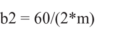
rather than
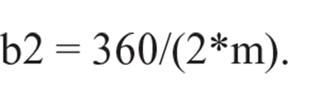
The execution of Scheme 2 with the above modifications will produce a single sector that should then be rotated (or rotationally replicated) to place the sector in the required position(s). For example, in Scheme 2, the insertion of the instruction

just before the ‘viewing particulars’ will produce the three high-amplitude sectors of Figure 24(a). The low-amplitude sectors can also be generated in the same way.
Multi-layer scallop domes
A scallop dome may consist of more than one layer of elements. For example, Figure 25(a) shows a ‘double layer’ scallop dome consisting of a ‘top layer’ of elements and a ‘bottom layer’ of elements, together with ‘web elements’ that connect the top and bottom layers. To help in visualising the scallop dome of Figure 25(a), the top layer elements are shown with slightly thicker lines. Also, small sketches of the top layer and bottom layer, as well as the web elements of the scallop dome, are shown below the dome in Figure 25(a1)–(a3).

A double-layer scallop dome and its corresponding unscalloped form.
The scallop dome of Figure 25(a) is obtained by scalloping the double-layer dome of Figure 25(b). The top layer of this dome, as well its bottom layer, has a ribbed pattern as shown separately in Figure 25(b1) and (b2). Also, the web elements of the dome are shown in Figure 25(b3). The dome has a large central opening (gap) with a diameter which is half the span of the dome. The double-layer ribbed dome of Figure 25(b) is similar to the dome shown in Figure 17 in FCP, section 1.9, where its formulation is discussed in detail. A similar formulation for the dome of Figure 25(b) is given here as Scheme 5:
(*) Scheme 5: Double Layer Open Ribbed Dome of Figure 25(b) (*) (*) Setting parameters (*) S = 50; (*) Span of top layer (*) C = 25; (*) Diameter of central gap (*) A = 45; (*) Sweep angle of top layer (*) D = 2; (*) Distance between the layers (*) m = 36; (*) Number of elements on a ring (*) n = 4; (*) Number of elements on a top rib (*) Rt = S/(2*sin|A); (*) Top circumradius (*) Rb = Rt-D; (*) Bottom circumradius (*) G = asin|(C/(2*Rt)); (*) Gap angle (*) T = (A-G)/(2*n); (*) Increment (*) (*) Formulating the dome in spherical coordinates (*) Top = rinit(m,n + 1,2,2*T)|[Rt,1,G; Rt,3,G]# rinit(m,n,2,2*T)|[Rt,1,G; Rt,1,G + 2*T]; Bot = rinit(m,n,2,2*T)|[Rb,2,G + T; Rb,4,G + T]# rinit(m,n-1,2,2*T)|[Rb,2,G + T; Rb,2,G + 3*T]; Web = rinit(m,n,2,2*T)|lamit(1,G + T)|[Rt,1,G; Rb,2,G + T]; (*) Transferring to Cartesian coordinates (*) Dome = bs(1,360/(2*m),1)|(Top#Bot#Web); (*) Setting viewing particulars and drawing (*) use &,vm(2),vt(2),vh(0,2*Rt,3.5*Rt, 0,0,0, 0,0,1); clear; draw Dome; <>
A slightly modified form of Scheme 5 can also be used to generate the scallop dome of Figure 25(a). To be specific, to modify Scheme 5, the statement that applies the ‘basispherical’ function (bs function) for transferring the spherical coordinates to Cartesian coordinates, namely
Dome = bs(1,360/(2*m),1)|(Top#Bot#Web); should be replaced by the corresponding statement for the ‘scallop basispherical’ function (sbs function), that is Dome = sbs(1,60,[Rt,A,4,4],1,360/(2*m),1)|(Top#Bot#Web);
Considering the definition of the sbs function (Figure 6), the above statement involves the following choices:
The first parameter of the sbs function represents the ‘mode’, which is chosen to be 1. This implies scalloping with ‘parabolic variations’ along both U2 and U3 directions.
The second parameter of the sbs function represents the ‘sectoral angle’, which is chosen to br 60°. This implies a total of six scalloped sectors.
The parameters Rt and A, in the square brackets, respectively, give the first and third spherical coordinates of the point at which the amplitude and prominence are specified. The choice of Rt and A implies that the point of specification is at the midpoint of a sector on the outermost ring of the top layer of the dome.
The remaining items in square brackets are 4 and 4, implying that both ‘amplitude’ and ‘prominence’ are 4.
The last three parameters of the above sbs function are ‘scale factors’ for the transformation of the spherical coordinates into Cartesian coordinate. Here, the only scaling required is for the U2 direction, since the formulation in Scheme 5 uses the actual values of the spherical coordinates in the first and third directions.
Another example of a double-layer scallop dome is shown in Figure 26(a). This is a double-layer scallop diamatic dome with small sketches of its top layer, bottom layer and web elements shown separately under it.

A double-layer scallop diamatic dome and its corresponding unscalloped form.
Also, Figure 26(b) shows the dome before scalloping. This double layer diamatic dome is discussed in detail in FCP, section 2.5 and a formulation for generation of the dome is given in FCP, Figure 20. This formulation has been used here to produce Figure 26(b). The same formulation is also used for producing Figure 26(a) in a similar manner as discussed for Figure 25(a). In this case, the statement that applies the ‘basidiamatic’ function (bd function) for transforming the diamatic coordinates to Cartesian coordinates, namely
F = bd(1,360/n,A/(3*m))|(TOP#WEB#BOT); should be replaced by the corresponding statement for the ‘scallop basidiamatic’ function (sbd function), that is F = sbd(1,60,[Rt,3*m,4,4],1,360/n,A/(3*m))|(TOP#WEB#BOT);
Scalloping a barrel vault
Consider the lamella barrel vault of Figure 27(a). This barrel vault will be subjected to various forms of scalloping, as described in the sequel. The barrel vault of Figure 27(a) has
A span of S = 40 m;
A rise of H = 8 m;
A length of L = 60 m.

Basic components of movement in the scalloping process of a barrel vault.
To scallop a barrel vault, its length is normally divided into a number of equal segments and all the segments are scalloped in the same way. In the present example, the barrel vault is divided into two segments with a ‘segmental length (or segment length)’ of Ls = 30 m, as shown in Figure 27(a).
Scalloping of a barrel vault involves three different types of component. First, there is the ‘amplitude’ which is a ‘vertical movement’ of the points of a segment, see Figure 27(b). The maximum magnitude of amplitude normally occurs at the midpoints of the ‘edges’ of a segment. This maximum magnitude in the example of Figure 27(b) is 4 m. The maximum amplitude decreases gradually towards the ‘side borders’, as well as the ‘crown line’ of a segment, such that the amplitude will be zero all along the side borders and the crown line of the segment.
The second type of component of movement involved in scalloping a barrel vault is ‘prominence’. This is an ‘outward horizontal movement’ of the points of a segment, see Figure 27(c). The maximum magnitude of prominence occurs at the same points where the amplitude is the maximum. The maximum value of prominence in the example of Figure 27(c) is 4 m. Just as in the case of the amplitude, the magnitude of prominence decreases gradually towards the ‘side borders’ and the ‘crown line’ of a segment, such that the prominence will be zero all along the side borders and the crown line of the segment.
The third type of component for scalloping barrel vault is ‘hump’. This is a vertical movement whose maximum value occurs at the centre of a segment. The maximum value of the hump decreases gradually as one moves away from the centre of the segment and will reduce to zero at all the points of the side borders, as well as the edges of the segment, see Figure 27(d).
It may be noted that the ‘amplitude’ and ‘prominence’ in the process of scalloping of barrel vaults have similarities to those in the process of scalloping of domes. However, the ‘hump’ is only applied in the case of barrel vaults and has no equivalent in scalloping of domes.
In the above description of scallop barrel vaults in Figure 27, reference is made to the ‘gradual reduction’ of amplitude, prominence and hump. But no indication is given regarding the rules by which the reduction takes place. These rules of variation are related to the ‘scalloping modes’, of which there are four. These modes are similar to the four modes of scalloping of domes as discussed in section ‘The sbs function’. The four modes of scalloping for a barrel vault are represented symbolically in Figure 28. This figure only considers the variations of amplitude and prominence, and the situation regarding hump will be discussed later.

Symbolic representation of the variations of amplitude and prominence for the four modes of scalloping of barrel vaults: (a) Mode 1, (b) Mode 2, (c) Mode 3 and (d) Mode 4.
Figure 28(a) shows a sketch of a scalloped version of the barrel vault of Figure 27(a), with an amplitude of 7 m and a prominence of −2 m, produced using mode 1. In this figure, the positions of maximum amplitude and prominence are encircled. Also, the directions of reducing magnitudes of amplitude and prominence are indicated by arrowheads. Three styles of arrowhead are used in Figure 28, where each style represents a law of variation. The simple arrowheads used in Figure 28(a) represent a parabolic law. This parabolic law of variation is the same as that used for the scallop domes. Thus, in mode 1, the maximum values of amplitude and prominence gradually decrease according to the parabolic law in the directions shown and reach zero at all the points of the side borders and crown line of every segment.
Mode 2 is symbolically represented in Figure 28(b). All the details here are the same as for mode 1, except that the law of variation is a sinusoidal one. Again, this sinusoidal law of variation is the same as that used in scalloping of domes. This law of variation in Figure 28(b) is represented by a ‘curly arrowhead’.
Mode 3, which is represented in Figure 28(c), is identical to mode 1, except that the law of variation in the direction towards the crown line is ‘linear’ rather than parabolic. The law of linear variation here is the same as that used for scalloping of domes. This law, in Figure 28(c), is represented by a ‘sharp arrowhead’. Comparison between Figure 28(a) and (c) shows that the effect of the linear variation is to produce a higher rise for the segments. This higher rise also creates a ‘valley effect’ along the crown line.
Mode 4 is represented in Figure 28(d) and is the same in every detail as mode 2, except the variation in the direction towards the crown line is linear rather than sinusoidal. It may be seen that the ‘valley effect’ of Figure 28(c) is present here as well.
Finally, as far as the ‘hump’ is concerned, its variation will be parabolic in both longitudinal and lateral directions, reducing the maximum magnitude of hump at the middle of a segment to zero at all the points of the side borders and the edges of the segment. The form of the hump is independent of mode and is the same for all modes.
The sbc function
The generation of a scallop barrel vault is achieved through a function called ‘sbc’, standing for ‘scallop basicylindrical’. The sbc function is available in Formian-K but has not been implemented in Formian-2. The constitution of the sbc function is shown in Figure 29.

Constitution of sbc function.
The function acts on the ‘argument’ E (which is a formex) and produces the result as formex G. Formex E represents a ‘cylindrical barrel vault’ which is formulated in terms of a ‘cylindrical normat (coordinate system)’. This is discussed in detail in FCP, section 1.8.
Figure 30(a) shows the cylindrical (normat) coordinate system U1-U2-U3 in terms of which the argument E is to be formulated. Also shown in Figure 30(a) is the Cartesian coordinate system X-Y-Z with respect to which the information in the result formex G will be given, see FCP, section 1.8. The other information in Figure 30 will be referred to in the sequel.

Coordinate systems involved in the formulation of a barrel vault.
The significance of the parameters of the sbc function in Figure 29 is explained as follows:
‘Mode’ can assume a value of 1, 2, 3 or 4 representing one of the four styles of variations of the amplitude and prominence, as discussed above (see Figure 28).
‘Ls’ is the segmental length (or segment length), as discussed above (see Figure 27(a)).
‘U1s’ is the first cylindrical normat coordinate of the points of specification of amplitude, prominence and hump, indicating the ‘cylindrical layer’ on which the points of specification are situated.
‘A’ is the ‘sweep angle’ of the barrel vault, as shown in Figure 30(b). The points of specification of amplitude and prominence will then be the midpoints of the left and right edges of the segments and the point of specification of the hump will be at the midpoints of the segments. The U2 cylindrical coordinates of the left edge, crown line and right edge are, respectively, U2 = 0, U2 = A and U2 = 2A.
‘Amp’, ‘Prom’ and ‘Hump’ are the specified magnitudes of amplitude, prominence and hump, respectively. The specified hump will always represent the ‘maximum hump’. However, the specified amplitude and prominence will be their maximum values provided that all the parts of the barrel vault (represented by argument E) are in-between the U2 = 0 and U2 = 2A edges. This condition is normally satisfied, but otherwise, the amplitude and prominence outside the edges may be larger than the specified magnitudes.
Finally, ‘b1’, ‘b2’ and ‘b3’ are the ‘basifactors’ of the ‘basicylindrical function (normat)’ used for the formulation of the argument E, see FCP, section 1.8.
To illustrate the application of the sbc function, let us begin by Scheme 6 below, which provides a formulation for generation of the barrel vault of Figure 27(a):
(*) Scheme 6: Lamella Barrel Vault of Figure 27(a) (*) (*) Setting parameters (*) S = 40; (*) Span in metres (*) H = 8; (*) Rise in metres (*) L = 60; (*) Length of barrel vault in metres (*) m = 8; (*) Frequency of crosses in U2 direction (*) n = 12; (*) Frequency of crosses in U3 direction (*) A = 2*atan|(2*H/S); (*) Sweep angle (*) R = S/(2*sin|A); (*) Circumradius (*) b1 = R; b2 = A/m; b3 = L/(2*n); (*) Basifactors of bc function (*) (*) Formulating the barrel vault in cylindrical coordinates (*) E = rinit(m,n,2,2)|lamit(1,1)|[1,0,0;1,1,1]# rinit(m,2,2,2*n)|[1,0,0; 1,2,0]# rinit(2,n,2*m,2)|[1,0,0; 1,0,2]; (*) Transferring to Cartesian coordinates (*) F = bc(b1,b2,b3)|E; (*) Making the Y-axis vertical (*) F = verad(0,0,90-A)|F; (*) Setting viewing particulars and drawing (*) use &,vm(2),vt(2),vh(2*R,3*R,-R, 0,0,L, 0,1,L); clear; draw F; <>
The formulation in Scheme 6 is discussed in FCP, section 1.8 (see Figure 14). To generate the configuration of Figure 27(b), all that is required is to replace the ‘bc function (basicylindrical function)’ in Scheme 6 with a ‘sbc function (scallop basicylindrical function)’. To be specific, the instruction
F = bc(b1,b2,b3)|E; should be replaced by F = sbc(1,30, [1,A,4,0,0], b1,b2,b3)|E;
Also, the configurations of Figure 27(c) and (d) can be generated by entering the appropriate specifications for amplitude, prominence and hump.
Scheme 6 may be used to generate many different scalloped versions of the barrel vault of Figure 27(a) by assigning different values to amplitude, prominence and hump as required. For example, three such scalloped versions are shown in Figure 31, with the corresponding amplitude, prominence and hump for each case given underneath. Note that the amplitude, prominence and hump can be positive or negative.

Examples of scallop barrel vaults generated by Scheme 6.
When scalloping a barrel vault, the position of its front end need not necessarily be at U3 = 0. For example, Figure 32(a) is a scalloped version of Figure 27(a) with the amplitude, prominence and hump as for Figure 31(a), but with the front end of the barrel vault at position U3 = −6. Also, Figure 32(b) and (c) show similar scalloped forms but with the positions of the front ends being at U3 = −8 and U3 = −4, respectively.

Variants of the scalloped barrel vault of Figure 31(a), with different positions of the front end: (a) U3 = −6, (b) U3 = −8 and (c) U3 = −4.
All the examples of barrel vaults considered so far have a lamella pattern. However, none of the concepts discussed is dependent on a particular pattern. In practice, a barrel vault can have many possible patterns, and an example of a non-lamella pattern is shown in Figure 33(a). The dimensions of this barrel vault are identical to those of the barrel vault of Figure 27(a).

Example of scalloping of a barrel vault with a non-lamella pattern.
Two scalloped versions of the barrel vault of Figure 33(a) are shown in Figure 33(b) and (c). The amplitude, prominence and hump for these barrel vaults are as follows: Amp = 8 m, Prom = −3 m and Hump = 3 m. The difference between the figures is that Figure 33(b) has Mode = 1 and Figure 33(c) has Mode = 2.
In choosing a pattern, it is important to ensure that the segmental subdivision is compatible with the pattern. For example, Figure 34(a) shows the barrel vault of Figure 33(a) divided into two segments, as indicated by thick lines. In this case, the border between the segments is in an acceptable position and thus the segmental subdivision is ‘compatible’ with the pattern. However, in the case of Figure 34(b), the longitudinal frequency of the elements of the pattern is such that division by two segments leaves the central border in an unsuitable position. In this case, the segmental subdivision is ‘not compatible’ with the pattern.

Compatibility and incompatibility of segmental subdivision and pattern.
Finally, Figure 35 illustrates the scalloping of a double-layer barrel vault. Figure 35(a) shows a double-layer barrel vault with a two-way (binate) pattern for both of its top and bottom layers. The formulation of this double layer barrel vault, using a cylindrical normat (coordinate system) is discussed in detail in FCP, section 1.8. The same formulation (with different parameters) has been used here to generate the barrel vault of Figure 35(a).

Scalloping of a double-layer barrel vault.
The scallop barrel vault of Figure 35(b) is generated using the formulation for Figure 35(a) by replacing the ‘bc function (basicylindrical function)’ with a ‘sbc function (scallop basicylindrical function)’.
Scalloping a toroidal barrel vault
A ‘toroidal barrel vault’ is a barrel vault whose curviance resembles a part of a ‘toroidal surface’ (doughnut-shaped surface).
Figure 36 shows a toroidal surface together with three types of barrel vaults whose nodal points lie on the surface. These are the basic types of toroidal barrel vaults and they are also shown in Figure 37. The toroidal barrel vault shown in Figure 37(a) is referred to an ‘outbent’ toroidal barrel vault. An outbent toroidal barrel vault is formed in the region of the toroidal surface around the ‘outer ridge’ of the surface. In fact, the outer ridge is coincident with the ‘crown line’, or more accurately, ‘crown curve’ of an outbent toroidal barrel vault. In a ‘cylindrical’ barrel vault, the crown line is a simple straight line. However, the crown curve of an outbent toroidal barrel vault is a convex arch.

A toroidal surface together with three basic types of toroidal barrel vaults.

Basic types of toroidal barrel vaults.
The second type of a toroidal barrel vault has a curviance of the form of the region of the ‘inner ridge’ of the toroidal surface. Such a barrel vault is referred to as an ‘inbent’ toroidal barrel vault, with its crown curve being a ‘concave curve’ coincident with the inner ridge of the toroidal surface, as shown in Figure 37(b).
The third type of a toroidal barrel vault has a curviance of the form of the region of the ‘side ridge’ of the toroidal surface. A barrel vault of this type is referred to as a ‘sidebent’ toroidal barrel vault, with its crown curve being coincident with the side ridge of the toroidal surface, as shown in Figure 37(c).
A convenient way of generating the geometry of a toroidal barrel vault is to use a ‘toroidal normat’. This can be done through the ‘bto’ function (basitoroidal function), as described in detail in FCP, section 3.4. A toroidal normat has four directions indicted by U1, U2, U3 and U4, as shown in Figure 38.

A toroidal normat.
Also shown in Figure 38 are the X-Y-Z axes of the corresponding Cartesian coordinate system. An example of a formulation for a sidebent lamella barrel vault is given as ‘Scheme 7’ below:
(*) Scheme 7: Sidebent Lamella Barrel Vault of Figure 40(a) (*) (*) Setting parameters (*) S = 20; (*) Span of barrel vault in metres (*) H = 3; (*) Rise of barrel vault in metres (*) R = 50; (*) Central toroidal radius in metres (*) T1 = 60; (*) Angular length of barrel vault (*) At = 0; (*) twist angle (*) m = 12; (*) Frequency of crosses in U2 direction (*) n = 6; (*) Frequency of crosses in U4 direction (*) A = 2*atan|(2*H/S); (*) Sweep angle of barrel vault (*) Q = S/(2*sin|A); (*) Radius of the cross-section of the toroidal surface (*) b1 = R; b2 = T1/(2*m); b3 = Q; b4 = A/n; (*) Basifactors of bto function (*) (*) Formulating the barrel vault in toroidal coordinates (*) E = tran(4,(At-A)/b4)|(rinic(2,4,m,n,2,2)| lamic(2,4,1,1)|[1,0,1,0;1,1,1,1]# rinic(2,4,m,2,2,2*n)|[1,0,1,0; 1,2,1,0]# rinic(2,4,2,n,2*m,2)|[1,0,1,0; 1,0,1,2]); (*) Transferring to Cartesian coordinates (*) F = dep(4)|bto(b1,b2,b3,b4)|E; (*) Setting viewing particulars and drawing (*) use &,vm(2),vt(2),vh(0,0,2*R, R,R/2,0, R,R/2,10); clear; draw F; <>
The parameters used in Scheme 7 are shown in Figure 39.

A sketch showing the parameters used in Scheme 7.
Scheme 7 has been used to generate the geometry of the toroidal lamella barrel vault of Figure 40(a). This is a sidebent toroidal barrel vault. But, its corresponding outbent and inbent toroidal barrel vaults are also shown in Figure 40(b) and (c).

Basic toroidal lamella barrel vaults generated by Scheme 7.
There is a simple relationship between the toroidal formulations representing the three configurations of Figure 40. To elaborate, let a formex Fa represent the sidebent barrel vault of Figure 40(a) in terms of toroidal coordinates. Then, the formex Fb representing the outbent barrel vault of Figure 40(b) may be obtained by rotating Fa by 90° in the U4 direction. Similarly, the formex Fc representing the inbent barrel vault of Figure 40(c) may be obtained by rotating Fa by −90° in the U4 direction.
In this context, the angle of rotation in the U4 direction is referred to as the ‘twist angle’ and is denoted by ‘At’. Thus, At = 0°, At = 90° and At = −90° correspond to the sidebent, outbent and inbent barrel vaults, respectively. Also, if the twist angle has a value other than 0°, 90° or −90°, then the result will represent an in-between type of form.
Figure 41 shows scalloped versions of the toroidal barrel vaults of Figure 40. The process of scalloping for toroidal barrel vaults is similar to that for the cylindrical barrel vaults as will be described in the sequel.

Scalloped versions of toroidal barrel vaults of Figure 40.
The sbto function
The ‘sbto function’ (scallop basitoroidal function) is the conceptual tool through which toroidal barrel vaults can be subjected to the process of scalloping. The sbto function, like the ‘sbc function’ (scallop basicylindrical function), is a Formian-K function and has no equivalent in Formian-2.
The constitution of the sbto function is shown in Figure 42. The significance of various items of the constitution is as follows:
Parameter ‘mode’, as usual, can assume one of the four values 1, 2, 3 and 4, specifying one of the four possible styles of variations. These modes are the same as those described in Figure 28 for cylindrical barrel vaults. The difference here is that the crown lines of the barrel vaults are ‘curved’ rather than ‘straight’.
Parameter ‘As’ (segmental angle) indicates the ‘segmental length’. However, the length of a toroidal barrel vault is determined by the central angle T1 (see Figure 39). Consequently, if the required number of segments is k, then As = T1/k.
Parameter ‘U3s’ indicates the layer of the toroid (torus) for which the amplitude, prominence and hump are specified.
Parameters ‘A’ and ‘At’ are the ‘sweep angle’ (see Figures 38 and 39) and ‘twist angle’, as explained in the description of Figure 40.
Parameters ‘Amp’, ‘Prom’ and ‘Hump’ are the required values of amplitude, prominence and hump.
Finally, the parameters b1, b2, b3 and b4 are the basifactors of the basitoroidal normat, as described in FCP, section 3.4.

Constitution of sbto function.
The toroidal scallop barrel vaults of Figure 41 illustrate the use of the sbto function. To elaborate, these barrel vaults are obtained using Scheme 7, with the statement
F = dep(4)|bto(b1,b2,b3,b4)|E; replaced by the statement F = dep(4)|sbto(1,T1/2,[1,A,At,4,0,4],b1,b2,b3,b4)|E;
Figure 41(a)–(c) correspond to At = 0°, At = 90° and At = −90°. All three toroidal scallop barrel vaults of Figure 41 have mode 1. The corresponding barrel vaults for other modes can be obtained by simply changing the mode of the sbto function. For example, with mode = 2, the barrel vaults of Figure 41 assume the forms shown in Figure 43.

Mode 2 versions of the toroidal scallop barrel vaults of Figure 41.
By choosing suitable values for the parameters of Scheme 7, it is possible to generate many interesting toroidal scallop barrel vaults. Four such examples are shown in Figure 44.

Examples of toroidal scallop barrel vaults.
The choices of parameters for generation of the toroidal scallop barrel vaults of Figure 44 are as follows:
Figure 44(a): T1 = 240°, m = 48, As = 30°, Amp = 4 m and Hump = 4 m;
Figure 44(b): T1 = 120°, m = 24, As = 30°, Amp = 8 m and Prom = 4 m;
Figure 44(c): T1 = 90°, m = 24, As = 45°, Amp = 8 m, Prom = −3 m and Hump = 6 m;
Figure 44(d): T1 = 150°, m = 27, As = 50°, Amp = −6 m, Prom = 6 m and Hump = 6 m.
Finally, it should be mentioned that a toroidal barrel vault may be combinational, that is, consisting of segments that have different particulars. Also, a toroidal barrel vault may be multi-layer.
Selective scalloping
Consider the configuration of Figure 45. This is a combinational sidebent toroidal scallop lamella barrel vault. It is ‘combinational’ because its segments are of different shapes. The configuration is generated with Scheme 7 using a strategy similar to that described for combinational scallop domes in section ‘Combinational scallop domes’. In this strategy, every segment of different shape is created separately and then transferred into the required position(s).

An example of a combinational sidebent toroidal scallop lamella barrel vault, with the segment numbers written under them.
There are three forms of segment in Figure 45 as follows:
For segments 1 and 6: Amp = Hump = 2 m;
For segments 2 and 5: Amp = Hump = 6 m;
For segments 3 and 4: Amp = Hump = 12 m.
The strategy of section ‘Combinational scallop domes’ for generation of combinational scallop forms is a valuable one. However, Formian has another strategy that can also be used in the present situation. This strategy is referred to as the ‘selective strategy’ and will be described here in terms of the example of Figure 45.
The selective strategy, as applied to the example of Figure 45, works by dividing the nodes of the configuration into groups, with each group consisting of the nodes in the segments that have the same amplitude and hump. Here, there should be three groups, namely, the nodes in segments 1 and 6, the nodes in segments 2 and 5 and the nodes in segments 3 and 4.
The group to which a node belongs should be identified by one of the coordinates of the node. For instance, in the present example, the toroidal coordinates of a typical node consists of coordinates U1, U2, U3 and U4. One can then add a coordinate U5 to act as the ‘group indicator’. Thus, for every node in segments 1 and 6, U5 could be 1. Also, U5 could be 2 for every node in segments 2 and 5 and U5 could be 3 for every node in segments 3 and 4. The coordinate that is chosen to be the group indicator is referred to as the ‘pointer coordinate’.
There is no single technique that may be suggested for setting the values of the pointer coordinates. The reason is that there are many factors that influence the best way of setting these values in different cases. However, whatever the particulars of a case, one can always find a simple way of achieving the purpose. For instance, in the case of the example of Figure 45, the following Formian-K instructions will allocate the group identification values 1, 2 or 3, as suggested above, to the pointer coordinates
E = pan(5,2)|E; (*) See FCP, section 2.A.13 (*) for E[i,j] do (*) Formian-K loop for all the nodes of E (*) if E[i,j,2] < 12 OR E[i,j,2] > 60 then E[i,j,5] = 1; else if E[i,j,2] > 24 AND E[i,j,2] < 48 then E[i,j,5] = 3;
These instructions should be inserted after the formulation of formex E in Scheme 7. Once formex E, with the correct values of pointer coordinates, is in hand, then it can be used as the argument of the ‘selective’ version of the sbto function whose constitution is shown in Figure 46. The constitution is the same as that of the basic sbto function, shown in Figure 42, except that
Numbers 11 to 14, rather than 1 to 4, are used to represent the modes. So, the mode values have the simultaneous effect of indicating the required laws of variation, as well as signalling that the operation is ‘selective’.
There is a ‘selection panel’ as the last parameter of the function. This panel specifies the ‘position’ of the ‘pointer coordinate’ (P), as well as the ‘value’ of the pointer coordinate for the selected group of nodes (V).

Constitution of the ‘selective’ version of sbto function.
The next step is to use the selective sbto function for each group of nodes and compose the results for the final answer. For instance, for the example of Figure 45, this operation can be performed as follows
F = sbto(11, 20, [1, A, 0, 12, 0, 12], b1, b2, b3, b4, [5, 3]) | sbto(11, 20, [1, A, 0, 6, 0, 6], b1, b2, b3, b4, [5, 2]) | sbto(11, 20, [1, A, 0, 2, 0, 2], b1, b2, b3, b4, [5, 1]) | E;
where the values of the sweep angle A and the toroidal basifactors b1, b2, b3 and b4 are as given in Scheme 7. The above instruction should be inserted into Scheme 7 after the instructions for the group identification of the nodes given above.
In this section, the idea of the ‘selective version (mode)’ of a function is exemplified in terms of the sbto function. However, the other ‘scallop functions’, namely, sbs, sbd and sbc also have their selective versions. The pattern is the same for all of them, that is, the only differences between a basic scallop function with its selective version are that mode of variations are represented by 11, 12, 13 and 14, rather than 1, 2, 3 and 4 and that the selective version has a ‘selection panel’ as its last parameter. In fact, a number of other Formian functions also have selective versions in a similar style.
Note that the selective version of the sbs function, as described in the Singapore paper, is only applicable to Formian-2 and all the selective versions of functions in Formian-K are in accordance with the style described in this section.
Concluding remarks
This article has explored the scalloped forms of domes and barrel vaults. Also, convenient practical ways of generation of geometry of the scallop configurations are discussed in some length.
Scallop forms can provide efficient structural solutions. This statement is based on the following reasoning: ‘Arch’ is an effective structural form and is extensively used in various types of structure. In particular, a cylindrical barrel vault is, in effect, a ‘continuous arch’. Even more effective is a toroidal barrel vault because it has the additional curving. Also, a dome works like a ‘three dimensional arch’. For these arch-based forms, the operation of scalloping adds another level of improvement due to the ‘local arching’.
Of course, in addition to the pure geometry, an efficient structure must have suitably chosen supports, well-designed and constructed connections. Also, not every form is suitable for any structural purpose. However, if the geometry of a scallop form suits a project, then it will provide an excellent starting point. ‘Starting point’ in the sense that when the general aspects of a form suit a project, there still remain many possibilities for adjustments, including the change of a ‘regular form’ to ‘freeform’, that can be done using the capabilities of Formian.
Footnotes
Declaration of conflicting interests
The author(s) declared no potential conflicts of interest with respect to the research, authorship and/or publication of this article.
Funding
The author(s) received no financial support for the research, authorship and/or publication of this article.