
Abstract
In this article, the implementation of the pitch-control option is described within the OpenFOAM computational fluid dynamics library supported by the preliminary results for a few representative test cases. The proposed pitch-control logic represents a simplified version of the typically model available for the load simulation based on blade element momentum theory codes. The control variable for the blade pitch regulation is the rotor rotational speed, for which an additional torque-speed controller determining the equilibrium between the aerodynamic and the electrical torque is required. The simulations are performed on the 80-m-diameter turbine used as a reference design within the SmartBlades project. The unsteady test cases are based on the assumption of rigid, not pre-bend blade, and refer to an emergency stop and an extreme operating gust. Results verified the correctness of the implemented control logic and its sensitivity to the control parameters, that is, the key factors for a successful regulation of power production and load mitigation in wind turbine design. The implemented simulation methodology constitutes the first step toward the reproduction of very complex operating conditions for wind turbines by means of accurate computations.
Introduction
During their operational lifetime, wind turbine rotors undergo a varied and complex scenario of conditions that are reduced for certification purpose to a limited, though relevant, number of design load cases (DLCs), typically investigated numerically by means of multi-body simulation codes. In this context, some approximations are included, as the beam structural modeling in place of shell or solid, or inflow wind characteristics, and many engineering models reproducing unsteady, three-dimensional (3D) aerodynamic phenomena.
The reliable capture of the aerodynamic loads is a fundamental requirement to establish adequate strategies for torque, pitch, and yaw controllers. Thus, the simplified aerodynamics supported by engineering semi-empirical models should be abandoned to include higher fidelity methods for the description of the fluid dynamic action exerted on the wind turbine rotor.
In this article, the implementation of the pitch-control option is described within the OpenFOAM CFD (computational fluid dynamics) library supported by the preliminary results for a few representative test cases. The proposed pitch-control logic represents a simplified version of a typical model available for the load simulation based on BEM (Blade Element Momentum theory based code), such as FAST (Jonkman and Jonkman, 2016), HAWC2 (Larsen and Hansen, 2015), Bladed (GL Garrad Hassan Ltd., 2012), OWLib (Thomas et al., 2014), etc. Since the control parameters are the key factors for a successful regulation of power production and load mitigation in wind turbine design, the proposed simulation methodology constitutes the first step toward the reproduction of very complex operating conditions for wind turbines by means of accurate computations.
The introduction of a pitch angle regulation for a wind turbine blade refers mostly to the implementation of a proper grid motion method and a control logic. Within the OpenFOAM library, many different grid motion possibilities are available. Some of them are based on sliding grid techniques, where the entire domain is divided in multiple regions sharing one or more interfaces: this allows for simulation of simple rotation and/or translation of one or more moving boundaries with respect to a fixed outer domain (Farrell and Maddison, 2011). Other grid motion methods refer to a deformation of the original grid to allow for body rigid motion and/or shape variation, such as in an optimization task. In these cases, there is no closed loop between the aerodynamic and the translation and/or deformation of the structure, thus excluding the fluid–structure interaction. A typical example is represented by the Laplace and solid body rotation stress equations that, however, exhibit severe limitation in case of large translations and rotations. To overcome such an issue, in the last years, an approach based on radial basis function interpolation was integrated into the OpenFOAM library (Bos et al., 2013), thus preserving the grid quality, by means of coarsening and smoothing of the radial basis function, even for large translations and rotations.
The evaluation of the effects of a controlled wind turbine blade shares many common aspects with the well-established analysis of control surface effectiveness in aeronautic research, such as the identification of a set of candidate configurations whose performance is to be compared against a reference uncontrolled case, sensitivity study on sizing parameters, relative positions, and so on. Recently, this topic has been re-visited focusing on application fields as stability and control of unmanned combat aerial vehicle (UCAV) (Schütte et al., 2014) and the regulation of a large wind turbine by a morphing trailing edge flap (Jost et al., 2016). In both cases, several configurations are taken into account in order to evaluate their beneficial effects for, respectively, increasing the stability and reducing the loads, but any transient effect is considered.
A recent attempt to include the control strategy actively within a CFD simulation for wind turbine has been reported in Oe et al. (2016), where the mitigation on fatigue loads by means of the IPC (individual pitch control) regulation is shown. An alternative to the implementation of the control logic directly within a CFD library has been addressed during the last years by several authors. Restricting the consideration within the wind energy application are to be mentioned the proposals of coupling CFD with BEM codes reported in Churchfield et al. (2012), Heinz et al. (2013), and Li (2014), where a multi-physics environment for complete aero-servo-elastic simulation demonstrates its advantages in reducing the uncertainties in load estimation for complex operating conditions. However, only in Churchfield et al. (2012), the co-simulation is assessed between two open source codes, namely, FAST (Jonkman and Jonkman, 2016) and OpenFOAM. 1
The implementation proposed in this article assumes that the control variable for the blade pitch regulation is the rotor rotational speed, for which an additional torque-speed controller determining the equilibrium between the aerodynamic and the electrical torque is required. The simulations are performed on the 80-m-diameter turbine used as a reference design within the SmartBlades project (Tessmer et al., 2016), whose aim is the development of both passive and active technologies to reduce the applied loads, thus extending the operating life and reducing the costs. In fact, the goal of this research activity concerns the provision of numerical methodology that could handle complex aero-servo-elastic phenomena arising from the longer and slender blades for the ongoing 8 MW and more wind turbine development. The unsteady test case is based on the assumption of rigid, not pre-bended blade. They refer to an emergency stop and an extreme operating gust (EOG). Results verified the correctness of the implemented control logic and its sensitivity to the control parameters.
The structure of the article is as follows: in the section “Methodology,” numerical methodology is described; in the section “Results,” the test cases are detailed and the results are reported; and the conclusions and future outlooks are summarized in the final section.
Methodology
The pitch-control option is necessarily coupled to a simple model of variable-torque/variable-speed generator control option. In fact, the reaction of the pitch-control actuator is based on the error between the reference and the actual value of the generator speed, respectively, Ω
Torque-speed control
The torque control solves the rotor/generator dynamics equation, considering the inertia of both components connected to the shaft. The generator torque, or characteristic curve, consists of a look-up table depending on the rotational speed. The table should be provided by a consistent preliminary CFD simulation for constant tip speed ratio (TSR;
Pitch-control description
The pitch control implemented is based on the one used for the load simulation with BEM code. It is a proportional-integral (PI) kind, with gain scheduling (GS) and anti-wind-up (AWUP). The control logic provides limits for both angular speed (normal and emergency state) and angular position (rest and parking position), and see Tessmer et al. (2016) for more details. The inertia of the rotor around the pitch axis is neglected. In Table 1, the parameters for the two versions of the control strategy are shown: PI-IWES and PI-FW, respectively, for the IWES and ForWind implementation.
Parameters for the proposed proportional-integral control logics.
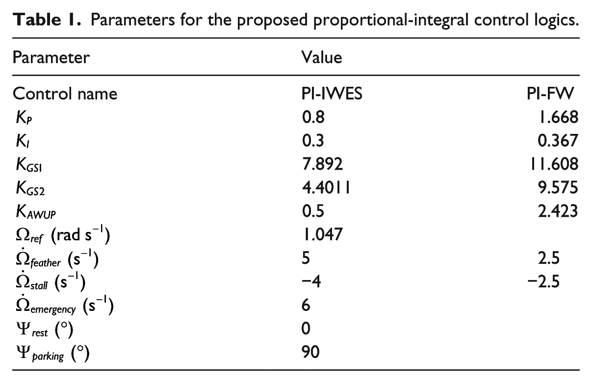
The code is able to integrate also C++ code obtained by a translation of MATLAB/Simulink pitch control model, and see Tessmer et al. (2016) for more details, whose main characteristics are summarized in Table 1, column 2. In this case, a fine pitch between torque and pitch control and a series of filters are included.
CFD integration
The integration of the pitch-control dynamics within a CFD model could be done following two ways:
Provide a separated domain for the rotor disk that slides inside the rest of the domain, plus the blade region that slides inside the rotor one because of any variation in the pitch angle. This is a quite general approach and could be used when wind shear, yawed inflow, and tower effects have to be investigated. However, this approach requires the discretization of the full domain and thus, for unsteady computation a considerable amount of time to be solved.
Provide a separated domain only for the pitch-control region and simulate only one-third of the domain by means of periodic condition. This approach reduces the number of cells and thus the required time for a computation.
Since the unsteady simulation could be quite demanding in terms of computational time in the performed simulations, the second approach is used. The numerical solution is based on the usage of a fully structured grid with full resolution of the boundary layer close to the blade surface (Rahimi et al., 2016), having

Sketch of the computational domain employed for the simulations. The regions interested by the controlled motions are rotor, where the torque-speed control operates, and pitch, where the pitch-control acts.
Control strategies
The action of controlling the rotor, that is, promoting a solid motion of the entire mesh or only a part of it, could lead to sudden change of the aerodynamic forces if the time steps for the solution of both fluid and control dynamic are not small enough or adequately combined. This may cause a destabilizing request for both torque and pitch controller. In order to avoid an unrealistic behavior, different control strategies could be adopted.
For instance, a reduction in the time step could lead to a smoother transition of aerodynamic loads, but this would increase the computational time.
A second issue could be related to the implementation of a sampling time for control update that differs from the time step for CFD solution. In this case, the control motion is performed with lower frequency, avoiding the occurrence of destabilizing control actions. On the other hand, both the implemented pitch and torque options have some motion rate limiter, based on those present in BEM-code model.
It should be kept in mind that the rate of action (or acceleration) related to both torque and pitch control have very different scale. For such a reason, in order to avoid oscillations in the CFD solution, a pitch acceleration saturation should be implemented, such as to provide smooth transition for the control action.
A further possibility included in the control option is related to the selection of a defined time to let the control action to be started. This could help when the initial transitory phase of the simulation would be skipped.
Results
The unsteady test cases are based on the assumption of rigid, straight blade. They refer to an emergency shut-down procedure where the blade is demanded to reach at maximum pitch rate the parking position (aligned to feather direction, that is, aligned with the incoming wind, normal to the rotor plane); a sudden step change in the inflow speed; an EOG situation, representative of the DLC 2.3, 3.2, and 4.2 (International Electrotechnical Commission (IEC), 2005).
Emergency shut-down
In the case of an emergency shut-down, the blade is forced to reach the feather position (90° with leading edge aligned to face the incoming wind direction) in order to reduce the thrust and thus the load on nacelle and tower. The rotational speed would reduce because of the reduction in the mechanical torque, that is, the power extracted from the wind.
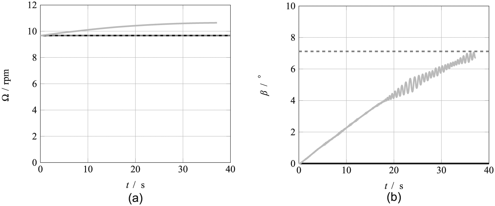
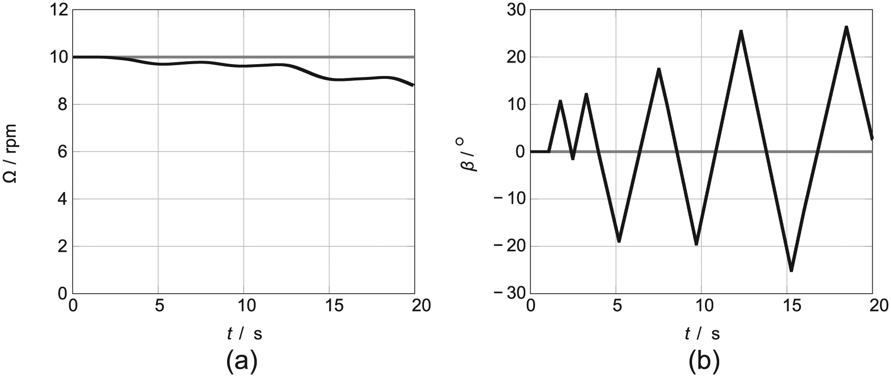
This operation took about 16 s to be accomplished within the simulation (and about 16 day of computing time on a 256 core simulation), as can be observed in Figure 2, where gray and black lines depict, respectively, initial and actual values for the rotational speed and the pitch angle. The rotational speed reached the minimum limit fixed to 5 r min−1 that corresponds to the cut-in speed of the generator. At the same time, the pitch angle is at its limit position equal to 90°. The simplified control pitch-logic doesn’t include a particular case in such condition, inducing a continuous oscillation of the blade around its feather position (see Figure 2(b)). A small phase of equilibrium is observed for the rotational speed right after the cut-in is reached (Figure 2(a)), then it keeps reducing its value because of the lack of the generator resistance.

Emergency shut-down case: (a) rotational speed and (b) the pitch angle. Legend for both plots: — emergency shut-down; - - steady case.
The feather position is characterized by a low value of thrust and thus on the rest of the wind turbine structure. This verified from the numerical results and shown in Figure 3, where for completeness the mechanical power is also reported. Again in these diagrams, gray and black lines depict, respectively, initial and actual values for plotted quantities.
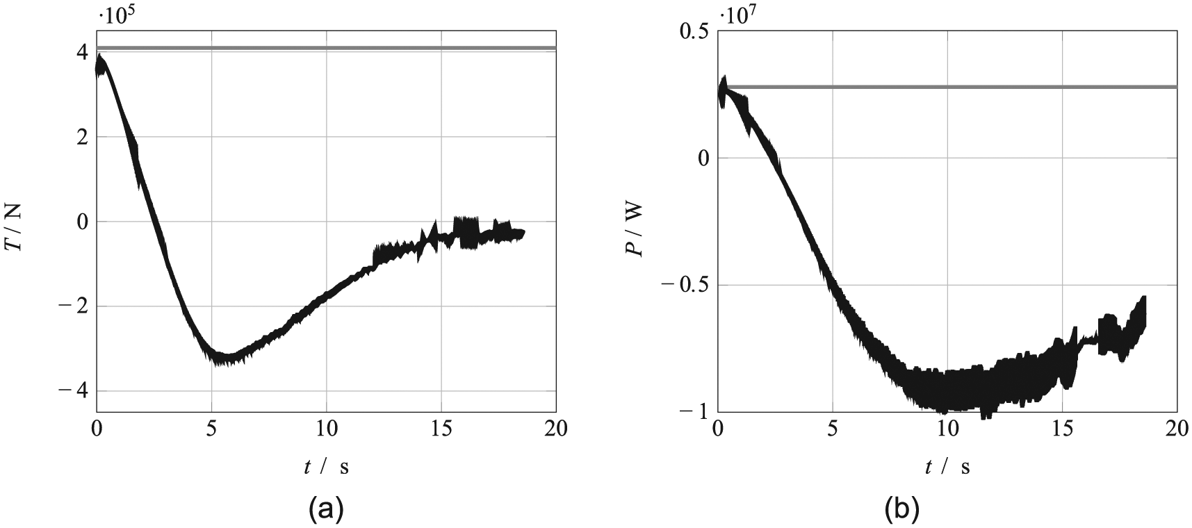
Emergency shut-down case: (a) the thrust on the blade and (b) the mechanical power. Legend for both plots: – emergency shut-down; — steady case.
Step gust
In this case, the turbine undergoes a sudden change of the inflow wind speed from the normal operating condition, namely,
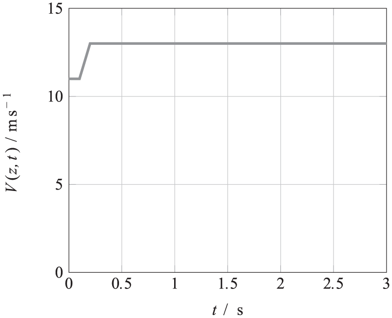
Boundary condition for a step velocity change.
The results are divided into two different situations: in the first one the control is switched off, while in the second it is on.
In the following diagrams, the time histories of a single blade power and thrust are shown. The blade is not controlled at all, and it must withstand a gust of
The power rises almost linearly with the increase in wind speed, then it reaches a stable value due to the new inflow wind speed value equal to
For the case with step-up gust and controlled turbine, both power and thrust oscillate but converge in time (see Figures 5 and 6(a) and (b)). This is due to the action of the pitch controller (see Figure 7(b)) that tries to restore the rotational speed to its initial value (see Figure 7(a)). The results show that even a larger time interval should be simulated in order to provide complete information on the behavior of the controller. It is worth to underline that this kind of simulation takes about 1 day (for a 256 cores distributed run) for 1 s of simulated time.

Step-up case: (a) the thrust on the blade and (b) the mechanical power. Legend for both plots: – steady case

Step-up controlled case: (a) the mechanical power and (b) the thrust on the blade. Legend for both plots: – steady case
Step-up controlled case: (a) the rotational speed and (b) the pitch angle. Legend for both plots: – steady case
EOG
In this case, the turbine undergoes an EOG from the normal operating condition, namely,

Boundary condition for an EOG velocity change.
After the standard IEC-61400-1:2005 (IEC, 2005), the gust velocity for the EOG case could be evaluated as follows
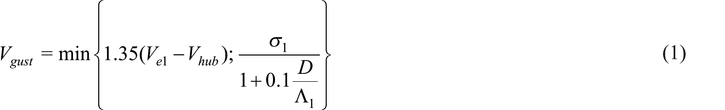
where

where
Consequently, the wind speed is

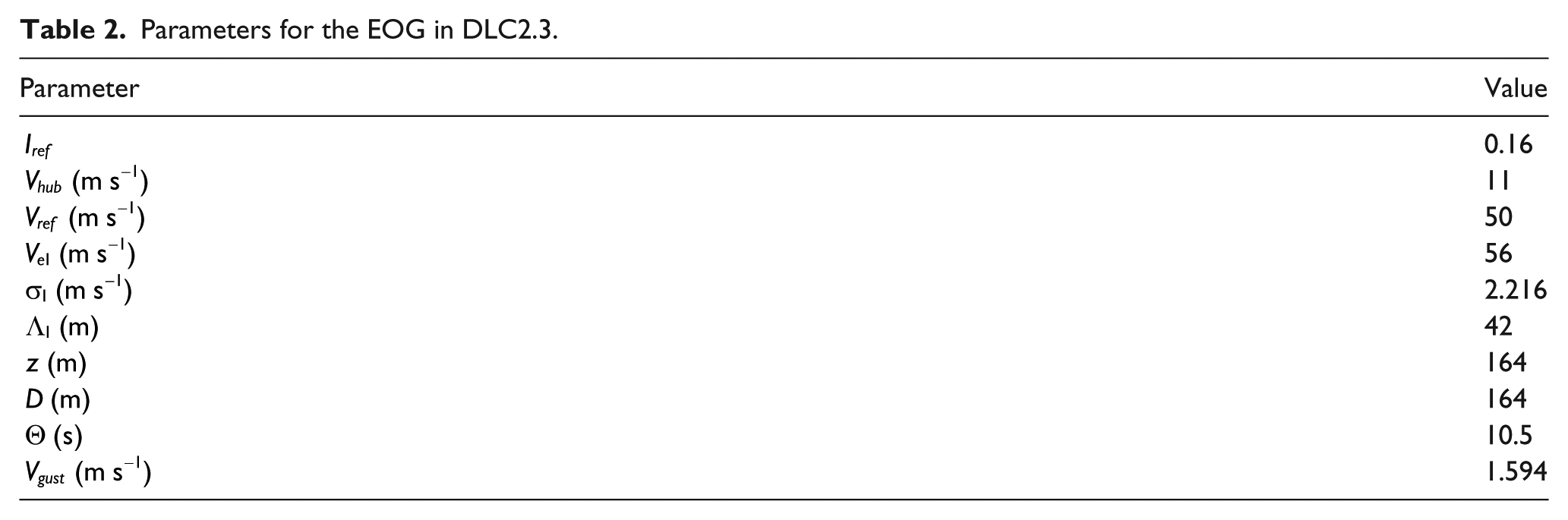
For the DLC 2.3, a possible choice for the EOG parameters is summarized in Table 2.
Parameters for the EOG in DLC2.3.
Both a simplified PI and an external MATLAB/Simulink C++ pitch control are employed. In the following, the simplified PI control is referred as IWES because it reproduces the main features of the pitch control used within the FAST model adopted in IWES—see Tessmer et al. (2016)—while the external MATLAB/Simulink C++ pitch control is referred as FW because it reproduces the one developed at ForWind—see Tessmer et al. (2016).
IWES PI control
The simplified PI pitch control reproducing the FAST model of the turbine is employed in this subsection, and it is labeled as IWES. The blade is controlled, and it must withstand an EOG from the design point condition
Parameters for the proposed proportional-integral control logics.

In Figure 9(a) and (b), the time histories of a single blade thrust and power, respectively, are shown. Both quantities exhibit the same behavior of the inflow speed in time, due to the action of the pitch controller. The results show that as the gust vanishes (10.5 s), the initial values for both power and thrust are stabilized around a value slightly different from the initial one. This difference arises from the discrepancies between the generator characteristic curve, provided as input table for the torque-speed controller, and the actual mechanical torque extracted from the unsteady simulation. The sensitivity to the controller gains’ values is negligible for both displayed quantities.
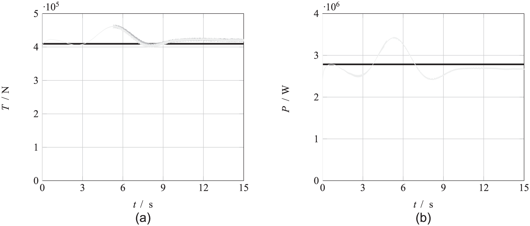
EOG case, IWES proportional-integral control: (a) the thrust on the blade and (b) the mechanical power. Legend for both plots: – reference value; — Set 0; — Set 1; — Set 2.
The behavior of rotational speed follows to some extent that of the wind speed. However, as the gust vanishes, the value of the rotational speed does not recover to the initial value (see Figure 10(a)). This misbehavior is to be ascribed to the discrepancies between the simplified torque-speed control implemented and the actual aerodynamic torque exerted on the blade during the unsteady simulation. This induces an equilibrium point for the generator at a rotational speed lower than the one available in the torque-speed look-up table. The sensitivity to the controller gains’ values is negligible for the rotational speed, beside some very little difference for the case with Set 2 if compared with the cases for Set 0 and 1 (see Table 3).

EOG case, IWES proportional-integral control: (a) the rotational speed and (b) the pitch angle. Legend for both plots: – reference value; — Set 0; — Set 1; — Set 2.
The behavior of the pitch angle is consistent with that of the rotational speed (see Figure 10(b)). As soon as the rotational speed value falls below the rated one, the pitch control starts to oscillate around zero, that is, the rest position. In the results for the pitch-control Set 1, conversely from the results of the case with the Set 0 for the gains, it appears a second diverging-converging oscillation starting at about 12 s. This leads to oscillations, from about 12 s, in the behavior of thrust and power in comparison with the Set 0 (see for power and thrust, respectively, Figure 9(a) and (b)). The maximum required pitch action is lower than that in the case with initial gains’ values. In the results for the pitch-control Set 2, a higher maximum pitch action with respect to the case for the Set 0 is observed. Moreover, the oscillation after the end of the gust resulted smaller than the one observed for the case with Set 0.
FW PI control
The external MATLAB/Simulink C++ pitch control reproducing the ForWind (FW) model is employed in this subsection. In the following diagrams, the time histories of a single blade power and thrust are shown. The blade is controlled, and it must withstand an EOG from the design point condition
Both power (and torque) and thrust are presenting an extreme oscillating behavior (see Figure 11). This is due to the action of the pitch controller (see PI-FW in Table 1). The results show that as the gust vanishes (10.5 s), the initial values for both power and thrust are not recovered.
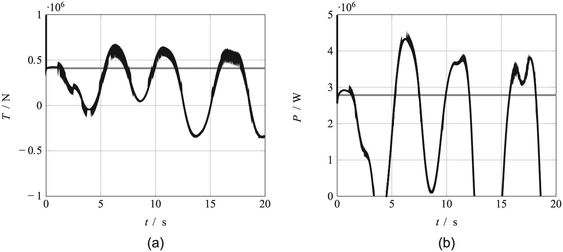
EOG case, FW proportional-integral control: (a) the thrust on the blade and (b) the mechanical power. Legend for both plots: – controlled case; — steady case
The behavior of rotational speed follows to some extent that of the inflow wind speed. However, as the gust rises (about 5 s in time), the value of the rotational speed depart from the expected behavior, see Figure 12(a), due to the unexpected pitch control command.
EOG case, FW proportional-integral control: (a) the rotational speed and (b) the pitch angle. Legend for both plots: – controlled case; — steady case
The behavior of the pitch angle is inconsistent with that of the rotational speed (see Figure 12(b)). The extreme responsiveness of the control with respect to rotational speed change introduces an oscillatory behavior that does not match the desired blade response.
Conclusion
A torque speed and pitch control have been implemented in OpenFOAM CFD library, allowing the simulation of the dynamics for wind turbine rotors. The torque-speed control is based on a simple induction generator model considering the inertia of both rotor and generator around the shaft and the balance between mechanical and electrical torques. The pitch control model is of PI type, with two different possibilities concerning the correction of integral error and GS: one reproduces the FAST-BEM model by Sevinc, while the other linked via a C++ code to the one implemented into Simulink by Unguran, see in both cases Tessmer et al. (2016). Some further optional parameters have been added, such as control update frequency (could be different, and lower than the one related to CFD calculation), rate limiter for torque and pitch action, and start time for control calculation (allowing transitory initial CFD calculation not to be considered).
The implementation of the dynamic mesh motion library has been verified by means of several test cases. First, the case of an emergency shut-down shows the capability of the model to reproduce the motion toward feather position of the blade (at maximum emergency rate) together with the slowing down of the turbine toward the generator cut-in rotational speed. Second, a few cases for step gust at inflow have been proposed. These show the qualitatively behavior of the controlled blade with comparison to a non-controlled one. After a certain time lag, the blade attempted to reach a steady state where the rotational speed, and thus the power, returns to the initial not perturbed value. Finally, a more realistic case is considered where the blade undergoes an EOG, representative of the design load case (DLC) 2.3, 3.2, and 4.2 (see IEC, 2005). For such a case, two different pitch controls mentioned above are used, showing very different behaviors. The simpler IWES PI control is able to provide a realistic response of the blade under gust, returning to the initial state after the gust has finished. The more complex FW PI control provides a strong oscillatory behavior, characterized by high responsiveness of the pitch control, and thus a not converging solution for both power and thrust.
By means of the test cases, the successful implementation of turbine control dynamic mesh motion library in OpenFOAM has been shown. A big challenge resides in the calibration or tuning of both torque-speed and pitch controls considering to CFD 3D unsteady simulations to:
Determine a wind inflow speed against power curve for the blade based on 3D CFD unsteady simulation, able to determine the pitch demanded angles in the over-speed region. This would also provide the torque-speed control look-up table to be used for the torque controller.
Evaluate the sensitivity of the turbine power with respect to the pitch angle variation in several over-speed condition in order to tune the pitch control parameters to provide a stable behavior of the blade. Other aspects such as load limitations are of course excluded.
Further investigations on the sensitivity of the implemented pitch control option with respect to its main parameters are scope of the follow-up project, 3 where the full coupling of the OpenFOAM dynamic mesh library with the BEM code FAST is considered. Of particular interest would be in this case the assessment of whether the URANS (Unsteady Reynolds Averaged Navier-Stokes equations) scheme is suitable for the unsteady aerodynamics modeling undertaken, for instance comparing BEM simulations, where usually a very simplified unsteady wake is assumed, against the higher fidelity simulations shown here.
Footnotes
Notation
Acknowledgements
The computations were performed on FLOW (Facility for Large-scale cOmputations in Wind energy research, ![]() ) at the University of Oldenburg. The author would like to acknowledge the Fraunhofer IWES colleagues Dr Jonas Schmidt and Hamid Rahimi, MSc, for, respectively, the support in implementation of the library and grid generation for the simulations.
) at the University of Oldenburg. The author would like to acknowledge the Fraunhofer IWES colleagues Dr Jonas Schmidt and Hamid Rahimi, MSc, for, respectively, the support in implementation of the library and grid generation for the simulations.
Declaration of conflicting interests
The author(s) declared no potential conflicts of interest with respect to the research, authorship, and/or publication of this article.