
Abstract
In the domain of Horizontal Wind Turbines, the key role of blade material and process selection is discussed. Existing methodologies and manual manufacturing processes, while addressing this issue, suffer from complexity and environmental drawbacks. To mitigate these issues, the study introduces a comprehensive methodology for the selection, implementation, testing and analysis of materials and processes for small blade construction, taking into account various constraints. The research conducts a thorough exploration of manufacturing processes, considering factors such as time, affordability, machine accessibility, repeatability, elements to be manufactured, and adaptability to complex surfaces. A systematic comparison of materials and processes, along with proposed filtering methods, reveals that rotomolding/polyurethane casting exhibits superior performance due to improved energy capture and inertia. The study underscores the importance of careful material and process selection to optimize blade efficiency and highlights the need for further research to address mechanical, economic, environmental, scalability, and material advancement challenges.
Introduction
The power generation industry is increasingly adopting renewable sources, such as wind and solar energy. Wind turbines (WTs) are poised to play a significant role in this transition (Malik et al., 2021). WT designers are currently exploring the use of larger rotor blades to maximize turbine energy extraction. However, designers face challenges related to time and energy requirements for the production and transportation of rotor blades as their size increases (Bošnjaković et al., 2022). WT blades are typically constructed using a combination of carbon and/or fiberglass composites and thermoset resins, with material and labor expenses encompassing 51% and 41% of the total cost of the blade, respectively (Schubel, 2010).
Although turbine blades are an important feature of wind installations, their manufacturing process poses significant challenges of Energy Efficiency and Energy (2017), accounting for about 15-20% of the production cost of a wind turbine. (Jureczko et al., 2005). Composite materials, with their unique combination of properties, are favored in the wind energy industry over other alternatives (Composites E, 2023). However, the future cost of raw materials, including glass or carbon, is directly linked to the manufacturing process. There are difficulties in creating new blades that optimize various variables that directly impact the final manufacturing cost (Jureczko et al., 2005; Rashedi et al., 2012).
Similarly, turbine manufacturers are increasingly producing their own blades using various materials and manufacturing techniques, as stated by Griffin and Ashwill (2003). These methods include hand-laying fiberglass structures in an open wet process, carbon-based epoxy wood enhanced, preimpregnated fiberglass, and techniques such as Vacuum-Assisted Resin Transfer Molding (VARTM) or preimpregnation of fabrics with subsequent vacuum exposure.
There is a great opportunity to enhance the process of selecting recyclable and eco-friendly composite materials for customized wind turbines (Chen et al., 2019). Furthermore, inflationary pressures are increasing the cost of conventional materials, increasing interest in the selection of materials for wind turbines (Rashedi et al., 2012).
On the other hand, according to Rashedi et al. (2012) and Maskepatil et al. (2014), the principles of material selection are based on properties such as low density, high resistance to tension, compression, and fatigue, as well as strength and adaptability to environmental conditions such as rain, humidity, dust, insects, and contaminants. These materials must withstand such conditions without corroding or wear, be easily transportable, exhibit excellent rigidity, and be manufacturable at a reasonable cost with a short construction time. Moreover, they should have an extended life and high durability. Grujicic et al. (2010) proposed a material selection process that identifies the most critical properties of a blade, including high rigidity, low mass density, and excellent resistance to fatigue.
This article aims to gather information, examine studies, and consider important features related to materials and manufacturing processes for the construction of WT blades. This will be accomplished through a methodical approach involving the selection, implementation, testing, and analysis of various material and process alternatives for the construction of Horizontal-Axis Wind Turbine (HAWT) blades. This research examines the conceptual, theoretical, and experimental foundations that validate the current development of the field, emphasizing the importance of local applicability and production. A case study concentrates on small HAWT turbine blades possessing a bioinspired Wavy Leading Edge (WLE) geometry. Subsequently, the methodology is executed, covering different manufacturing methods and proposed materials. The goal is to analyze and determine the optimal combination of material and process that satisfies the specified requirements, starting from the definition of the case study.
Approach
To determine the appropriate material and process for a specific case study, various selection methods are evaluated. These methods help narrow down the search and adaptation process by following a series of steps to analyze each scenario presented, taking into account the variables and limitations that simplify the search. The design process for a product should be closely tied to and in line with the specific characteristics, qualities, variables, and attributes of the material to determine an appropriate production process. Prior research must be conducted to facilitate the selection process, which can be obtained through physical resources such as books, catalogs, and personal experience, as well as technical resources including articles, standards, and conferences.
To choose both a material and a process, it is vital to establish a comprehensive selection methodology that includes procedures for both materials and processes. When selecting materials, factors such as initial analysis, inspiration from previous applications, and similarity to materials used in comparable components should be taken into account. To optimize the manufacturing process and achieve an appropriate end result, it is critical to take into account current and local technologies. Various process technologies, such as shaping methods, fastening and joining techniques, surface finishes, and internal composition, should be evaluated and selected accordingly to eliminate unnecessary steps.
Figure 1 illustrates the methodology, which describes the steps taken to find materials and processes and the subsequent implementation of the options chosen. The methodology involves extensive exploration and experimentation, with detailed results presented.

Consecutive mind map methodology of exploring materials and processes.
Definition of the case study
The procedure outlined above starts with creating a particular case study that concentrates on small HAWT blades. These turbines are classified according to their swept diameter, in accordance with the IEC 61400-1 standard Commission (2013). Small turbines are defined as having a swept diameter of less than 16 m, medium turbines range from 16 to 36 m, and large turbines have a swept diameter of 36 m or more. The objective is to analyze and explore alternative materials for turbine blades, covering all design variables to ensure the best performance, cost effectiveness, strength, durability, and system integration.
The location of HAWT implementation is directly related to the exploration of alternative material-process combinations. Environmental and meteorological conditions are crucial in determining the appropriate mechanical, aerodynamic, and dynamic blade design.
It is crucial to introduce the case study with a clear vision of the project’s current status and model characteristics, including turbine size, general dimensions, desired blade features, specific material and process requirements, and a well-defined objective. This ensures that the design conditions are met and efficient results are achieved, taking into account variables such as structural strength, durability, and performance under various environmental conditions.
General search for materials and processes
This section outlines essential factors for designing blades for small HAWTs. The focus is on blade length optimization to enhance energy capture, the utilization of effective airfoils to decrease wind resistance, guaranteeing structural integrity against different loads (e.g. mechanical, aerodynamic, seismic), utilizing high-strength composite materials, and achieving uniform stress distribution through an optimal design. Ensuring durability and longevity is crucial for safe operation in harsh environmental conditions, as is reducing structural loads through weight and density factors during installation. Furthermore, consistent energy production relies on maintaining efficiency under varying wind conditions.
This involves first defining the boundary conditions for blade design and then gathering reliable information on composite materials, manufacturing techniques, and molding processes from credible sources. Material evaluation involves evaluating suitability based on factors such as strength, stiffness, density, availability, and cost. Similarly, the evaluation of manufacturing processes takes into account affordability, expertise, and implementation.
In addition, this section examines distinct alternatives inspired by related applications, analyzes their feasibility and limitations, and suggests methods to improve performance. Comparative analysis, supported by software or material databases with validated properties, assists in the identification of optimal material-process pairings, providing data-driven insights for decision-making.
Material selection
To ensure optimal system performance, it is crucial to define specific design requirements when selecting materials. These requirements include load capacity, boundary conditions, external loads, regulations, and standards (Bošnjaković et al., 2022). The effectiveness of the system is dependent on a clear understanding of both physical and mechanical properties. During the evaluation of materials, it is crucial to consider key properties such as fatigue strength, stiffness, flexural strength, corrosion resistance, and lightweight characteristics. The design variables should be analyzed and the data should be assessed to evaluate the performance and suitability of the materials for the intended applications. The aim of this evaluation process is to estimate expected outcomes and identify the most appropriate materials for prototyping tests. After choosing the appropriate materials, the phase of design optimization should focus on minimizing weight and maximizing efficiency. Iterative improvements in product design strive to achieve an equilibrium that meets the performance criteria while permitting consistent reproduction. Thorough quality control measures are essential to ensure uniformity and sustained performance throughout the production of the final product.
Process selection
When selecting a manufacturing process, it is crucial to carefully consider the material to be used, as it directly affects the process. This step should define all manufacturing requirements, such as physical aspects for dimensioning and specified tolerances, to ensure proper functioning during assembly and operation. Avoiding errors and inconsistencies is important. Based on previous research, additive manufacturing, manual processes, and machining techniques can be evaluated to achieve high accuracy on intricate surfaces and to secure uniform reproducibility with minimal variations. After material selection, it is essential to review the compatibility between the chosen materials and manufacturing processes, since the molecular composition of the material can be altered by different processes, affecting the material properties. To analyze technical and economic factors, it is necessary to comparatively evaluate the viability and feasibility of implementing each manufacturing process. Proceeding with the manufacturing of components may be based on technological limitations, budget constraints, affordability, expertise, and other variables acting as boundary conditions.
Manufacturing and experimental testing of the chosen material-process pairs
After selecting material and process according to the defined selection criteria in the methodology, establish test objectives to demonstrate proper blade functionality based on a variable of interest. These objectives will serve as validation metrics, providing blade efficiency results on wind incidence in terms of aerodynamic performance, resistance, stiffness, vibration, and aerodynamic loads, among other factors. Procedures and protocols are established to carry out the tests and carefully select the required equipment and measurement tools. The number of prototypes is determined on the basis of the chosen manufacturing methods and materials. Testing is accomplished by utilizing either a tailored test bench or physical prototypes specifically designed for appropriate installation of manufactured prototypes. This facilitates the collection of relevant data for research. Analyzing the results enables validation of the initially proposed objectives and determines whether the product achieves the highest level of satisfaction with respect to the recorded variable.
Final analysis and conclusions
The ultimate analysis gathers the data acquired from the experimental tests and forms the basis for determining replicability, as well as the improvement of the optimal materials and procedures for the turbine blades. On interpretation of the results, the production process is evaluated to identify any patterns, variations, or trends that may affect the final product and could potentially lead to its failure. A product with consistently replicable results can be achieved through careful analysis, interpretation, and design improvement of the data obtained. The objective is to ensure that each iteration yields the desired variable readings. This iterative process will help develop a highly efficient and reliable product for future use.
Implementation
There is a desire to incorporate diverse materials and manufacturing methods in WT blades that feature intricate geometries similar to the WLE. The objective is to assess the most appropriate approach by researching, comparing, experimenting, and constructing. This involves evaluating the use of tensile structures to determine if they can substantially decrease the weight of the blade with WLE geometry without sacrificing efficiency due to potential inaccuracies in the created shape. Through experimental testing, various combinations of materials and manufacturing processes have been assessed for production. The primary focus is on comparing the cost-benefit ratio of different options.
Definition of the case study
A preliminary study on varying parameters showed that specific changes in blade geometry and composite laminate layout can result in further improvements in the performance of HAWT turbine blades. Grujicic et al. (2010) suggested that the geometry of the blade plays a significant role in determining the performance of a HAWT turbine. This concept is demonstrated experimentally by Bernal-del Río and Osorio-Gómez (2020), obtaining that the WLE blade outperforms conventional blades in terms of power generation. The WLE blade incorporates a bioinspired design featuring fins reminiscent of those of whales, which enhance aerodynamic efficiency and leverage the wind more effectively. The excellent performance of the WLE blade is due to its unique geometry, which presents various protrusions on its surface. This makes it challenging to select the right materials and techniques to adapt them to the complex surface, as shown in Figure 2. The figure indicates the radius and curvature values using colors that correspond to the minimum and maximum values. The minimum values are in dark areas, and the maximum is at the leading edge of warm tones.
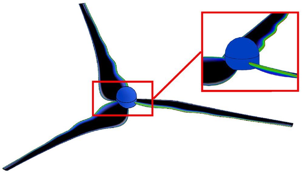
Wavy leading edge form—study surface.
It is acknowledged that the current manufacturing processes for the production of wind turbine blades are highly complex, requiring numerous variables and steps to achieve the desired final product that meets the aerodynamic standards without surface distortions Bucur et al. (2020). Therefore, the objective is to investigate feasible alternative options of material combinations and processes to enable local production of blades with more intricate designs, ensuring various factors such as affordability, durability, and aerodynamic smoothness. The results of this study have the potential to be replicated for other types of wind turbines that incorporate more conventional geometries. This could increase its relevance and applicability within the industry.
General search for materials and processes
Various materials and processes are currently used to fabricate airfoils. Steel and aluminum alloys are among these materials, but their high density limits their use to small-scale wind turbines. Composite materials are the most commonly used material in both small and large WTs. These materials consist of a matrix, such as polyurethane or epoxy resin, reinforced with materials such as fiberglass, carbon, or aramid fibers. These composites have the advantage of being lightweight and possessing high mechanical properties, such as tensile strength. However, their production may require specialized skills to ensure proper component formation, and their cost may be relatively steep. To make an informed decision, a thorough search is conducted in various databases to explore possible material and process combinations. Tools such as CES EduPack are utilized to gain a comprehensive understanding. Additionally, a systematic comparison is performed to determine the necessary characteristics for an appropriate WT blade design. These characteristics include:
Structural strength to withstand the forces experienced.
High fatigue resistance to handle all generated vibrations.
High rigidity to prevent longitudinal and transverse deformations.
Low density to reduce inertia and improve blade performance.
Ease of manufacturing, considering the cost-benefit factor.
Resistance to environmental agents such as erosion and corrosion.
Based on these factors mentioned above, comparative tables were developed among the various material families that are potentially suitable for implementation in the defined case study.
Metals
Metals with notable characteristics such as excellent electrical and thermal conductivity, high mechanical strength, versatility in production processes, minimal thermal deformation, and suitability within ambient temperatures are frequently used in commercial applications. These metals comprise machinable alloys, cast metals, stamped metals, forged metals, and dieless processed metals. Table 1 presents the metals that have been identified as having optimal qualities for use in HAWT blades.
Properties of Metals for blade manufacturing.

Based on the data analyzed, the combined strength and density of the aluminum and magnesium alloys make them strong candidates for manufacturing. While they are heavy, chromium-molybdenum and stainless steel offer excellent mechanical strength. However, metals like brass are not viable because of their low toughness relative to their density, which would require an increase in their thickness to meet application requirements. Therefore, an efficiently optimized manufacturing process could produce positive results with minimal material utilization.
However, the manufacturing processes available locally for these materials are limited to the following.
Machining two components on both sides and subsequently welding them together to create a smooth, high-quality surface finish.
Casting allows for the creation of intricate internal shapes within a component using a one-time mold. This process reduces material usage, strengthens areas prone to stress, and optimizes the weight-to-strength ratio of the component.
Dieless is an efficient and accessible technique to obtain two component sides and facilitate welding while remaining cost-effective.
In summary, the high initial cost of materials, including alloys, presents accessibility obstacles. The series 6000 aluminum alloys seem to provide ideal properties for customization through casting and/or machining in the manufacturing process, while the magnesium alloy can be effectively implemented using machining. However, despite their outstanding mechanical properties, metals are limited by their density, which results in increased weight. This weight issue complicates the resolution of rotor inertia, indicating that these materials may not be a high priority in manufacturing applications.
Polymers
This section discusses a broad variety of polymeric materials, including both amorphous and semicrystalline polymers. Examples of amorphous polymers are ABS, PVC, PC, PS, PMMA, etc., while PEEK, PET, PP, PTFE, etc. are examples of semicrystalline polymers. Both amorphous and semicrystalline polymers were selected as a result of their widespread use in current industries. Although they are uncommon in this specific application, they allow for a more comprehensive search to include commonly used polymers. An evaluation of material selection based on manufacturing processes was performed, taking into account thermoforming, CNC (milling-turning) and 3D printing, to determine feasible local manufacturing methods. Table 2 assesses the
Polymers for thermoforming process of blades.
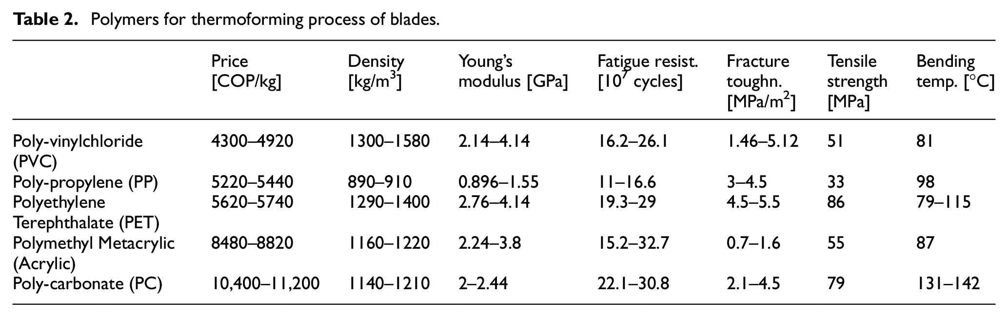
Based on Table 2, PVC is the most cost-effective material for thermoforming, PP has the lowest density, PET exhibits the best Young’s modulus, fracture toughness, and tensile strength, polycarbonate is the most resistant to flexural temperature, while acrylic is the most fatigue resistant material. The following polymer fabrication process is
Polymers for CNC machining process of blades.
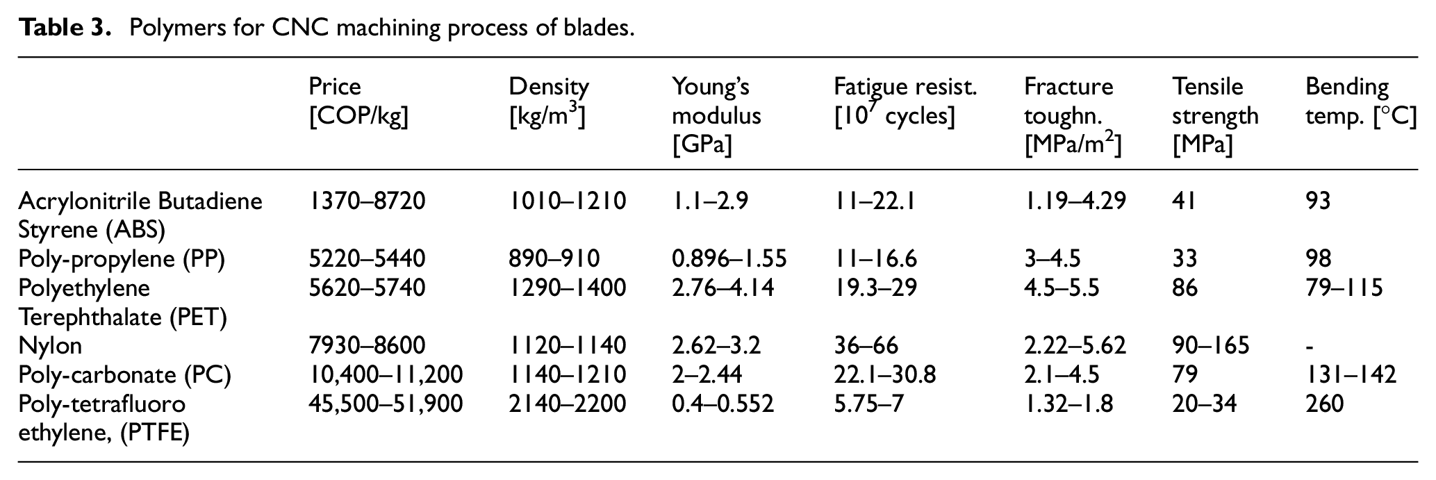
Based on the data presented in Table 3, ABS is the most cost-effective polymer for CNC machining, while PP is the least dense, PET has better elasticity, and nylon has the highest resistance to fatigue, fracture, toughness, and tensile forces. PTFE stands out as having the best flexural temperature.
ABS, nylon, and polycarbonate are suitable for the
In summary, when polymers are considered, it is generally accepted that polycarbonate and nylon are viable choices. Polycarbonate is suitable for thermoforming, CNC machining, and 3D printing, whereas nylon is suitable only for CNC machining and 3D printing, but not for thermoforming. Moreover, both polycarbonate and ABS can be utilized for all three production methods. Of the materials examined, ABS proves to be the most cost-effective, while polypropylene presents with the lowest density. In contrast, nylon boasts the highest fracture toughness. With regard to processes, each material is deemed suitable and feasible given current technological capabilities.
Composites materials
Composites are materials that consist of two or more components intentionally designed to improve their properties for specific uses or applications.
They comprise a matrix that provides adhesion and transfers external loads to the materials contributing to the mechanical properties. Additionally, there is a reinforcement component that adds rigidity and strength. Appendix Table 1 shows the materials used as matrices, focused on resins and Appendix Table 2 shows the reinforcements, focused on fibers.
Table 4 illustrates the predominant combinations of matrices and reinforcements, showcasing their high demand characteristics and properties in the market.
Composite materials for manufacturing of blades.
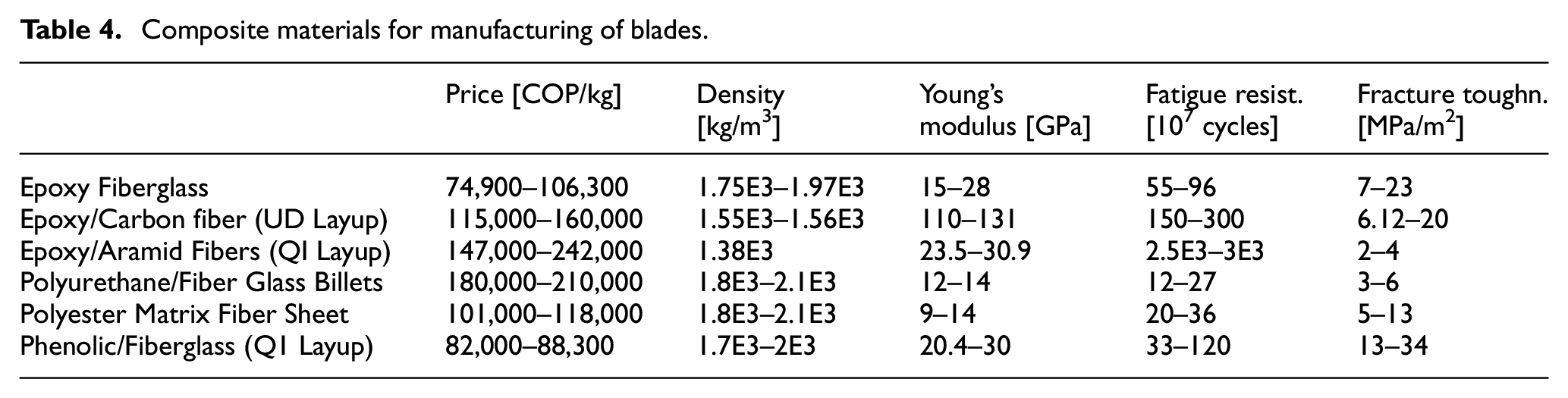
The epoxy resin reinforced with carbon fiber is notable for its outstanding physical and mechanical properties, making it a prevalent material in various industries. However, it is important to note that its high cost is one of the primary drawbacks compared to alternative options.
In terms of manufacturing methods, they can be categorized into open and closed molds.
For open molds, the following processes are used:
Hand Lay-up, which is a manual process of consecutively adding layers and bonding them together with resin.
Filament winding, which involves winding resin-soaked fibers onto a rigid, removable surface.
Vacuum bagging. This process involves manual placement of the component, consolidation of the composite layers through vacuuming, and application of temperature for curing.
For closed molds, the following processes are used:
Resin Transfer Molding (RTM): pressure and injects resin into dry fabrics that are already placed to optimize resin usage and improve mechanical properties.
Injection of pre-impregnated fibers with resin into closed molds.
Pultrusion: Stretches the material into a constant profile shape, followed by heat treatment to align and consolidate fibers.
Rotomolding: Resin and, in some instances, fiberglass are injected into a closed mold and the mold is rotated to ensure complete resin coverage and cure.
Now, the generalized search process for materials and processes can be implemented, followed by filtering the materials and processes found. This involves analyzing the various properties of each material and the respective processes to acquire an initial approach to the ideal materials for designing small WT blades. The CES Edupack software compares and analyzes materials and processes, utilizing a proposed filtering approach to analyze results.
Alternative materials
The CES Edupack software was utilized as a search tool to explore alternative materials. It presents results for materials mentioned above and also facilitates the discovery of new results by adapting search iterations based on designated criteria and search ranges for previously defined design variables.
It is clear that the use of composite materials, such as carbon fiber and different thermoplastic polymers outlined in Appendix Table 3, provides small wind turbine blades with distinct properties and adaptability to geometries that can withstand the loads encountered Alshammari et al. (2021).
It should be noted that higher values for Young’s modulus, strength, and fracture toughness indicate better material properties. Therefore, a direct comparison can be made between price and density. In this comparison, selection limits are established based on reference values for polymeric materials that meet the requirements, defining variables such as density (maximum limit: 1750 kg/m3), price (maximum limit: 120, 000COP/kg), Young’s modulus (minimum limit: 2:6 GPa), fatigue strength (minimum limit: 36 × 107cycles) and fracture toughness (minimum limit:
It can be analyzed that materials such as wood have an acceptable density, in addition to its tentative price and its affordability in manufacturing by CNC machining. On the other hand, composites are the best in several design conditions with affordable manufacturing processes, but their price is somewhat high. To carry out a more specialized search, it was decided to move on to level 3 analysis in the CES Edupack software, where a wider range of materials is available. The implementation of improved selection limits aims to find the optimal material for the application, taking into account preliminary design variables such as:
Maximum density of
Minimum Young’s modulus of 16.6
Fatigue resistance of
Fracture toughness of
Appendix Table 5 shows the main properties of the material most suitable for the application, based on the refined limits of the specified design criteria. It can be observed that there are more materials that meet even more demanding limits where Sisal and Juta materials stand, which are normally raw materials that are transformed into ropes, but stand out for their price, density, and mechanical properties, the worrying factor being the way they are processed. On the other hand, PET with 30% carbon fiber is an interesting option to evaluate, as well as fiberglass with polyester. Applying a final filter to all the searches compiled in the CES Edupack software, the most optimal alternative materials for manufacturing are determined and presented in Table 5, taking into account that in the search both nylon and fiberglass have already been previously mentioned previously, demonstrating the benefits in the application of the exposed case study.
Alternative materials for manufacturing of blades.

Tensile structures
One proposed alternative is inspired by the way the wings of early airplanes were made, using tensegrity structures to demonstrate how it is possible to achieve complex, doubly curved surfaces by using an internal structure and a flexible material stretched around it. This approach focuses on the relationship and combination of physical properties at the structural level.
For the external surfaces, the possibility of manufacturing them locally could also be explored using thermoforming and rotational molding of polymers and then stiffening them with the internal structure. The proposal is conceived for WT blades with a length of 30 m, which means that at this size, the stress, tension, and fatigue resistance considerations are more demanding than for a blade of a small WT. Additionally, the elements that make the design possible can be divided into flexible and rigid elements. Within the flexible elements, there are cables that act as tensioners and help to reinforce the textile membrane, which is responsible for defining the shape of the surface, is resistant and has a low density. In addition, edge reinforcements are placed along the edges of the membrane to absorb the tension generated at the edges and anchor points.
However, there are rigid elements that form the edges to provide support and shape to the membrane, which is constructed in an arched form. Anchor points provide stability by dissipating vibrations to the maximum extent while maintaining the necessary tension in the membrane.
The topic of tensile structures consists of three main elements: the tensioned element (fabric), the internal structure, and the tensioning elements.
First, an evaluation of the types of fabric available is made, as shown in Figure 3.
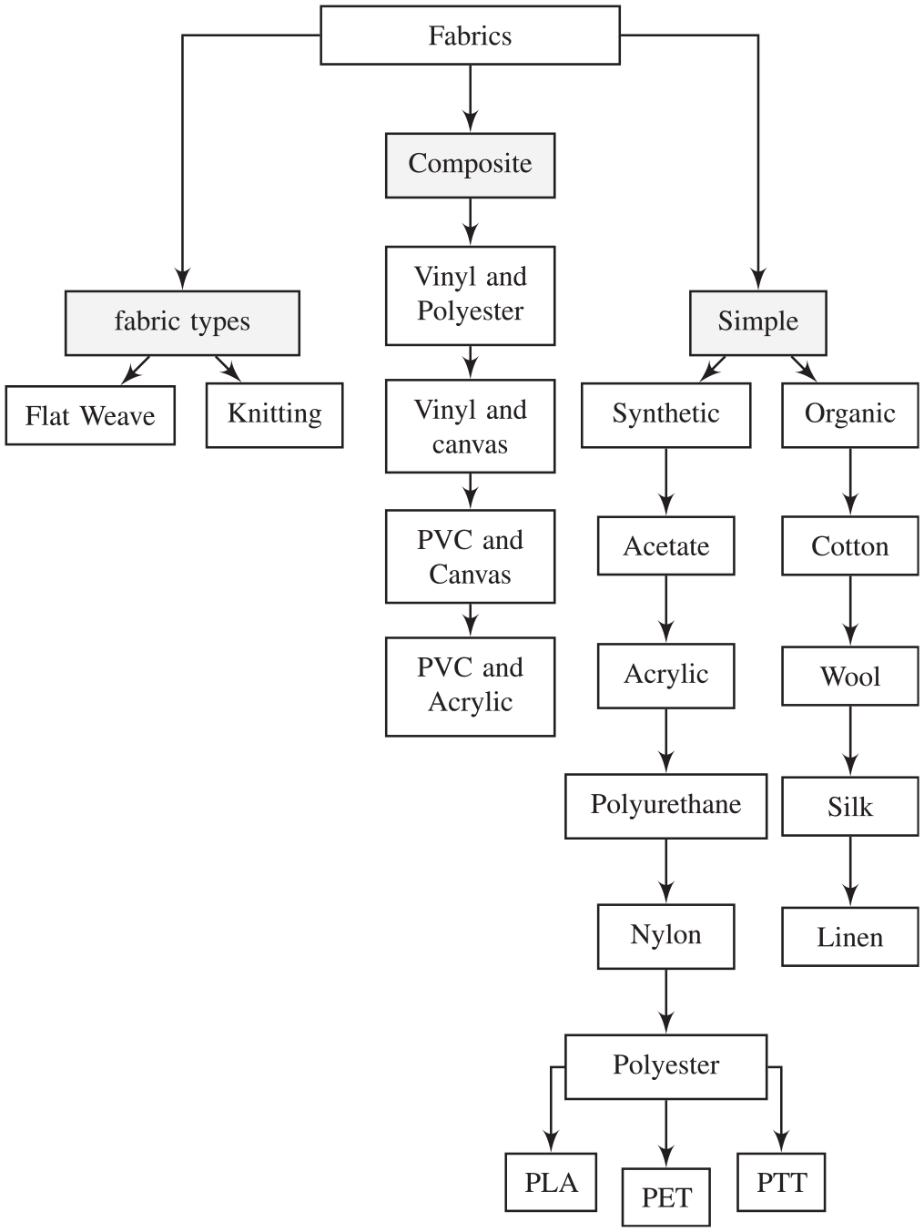
Different families of fabrics on the market.
Based on this, a search is made for commercial fabrics available in the industry that meet requirements and variables such as impermeability, tensile strength, fatigue resistance, durability, tear strength, wrinkle resistance, conformability, stiffness, sunlight resistance, and thermal stability. These fabrics are listed in Table 6.
Fabrics to consider for manufacturing of blades.

From there, the question arises as to the different methods of tensioning and forming the different types of fabrics. The most common tensioning methods used in industry are analyzed and presented in Table 7.
Types of tensioning strategies.
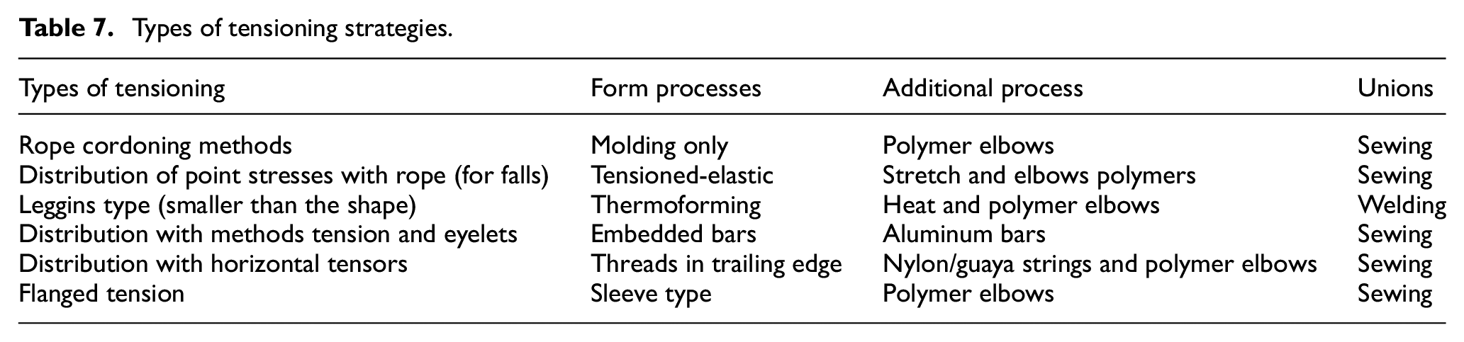
Taking into account the information above, the idea is to propose a process for designing tensile structures and compare it with other manufacturing processes found, since tensile structures are an interesting alternative to evaluate in terms of cost, ease of fabrication, and overall benefits.
Material selection
Table 8 shows the materials with the best properties that are most suitable for the case study.
Materials selected for manufacturing of blades.

Limitations related to affordability, availability, price, and implementation without experience are defined. From there, unconventional alternatives that meet the initial constraints are explored. These alternatives are classified on the basis of the implementation and exploration of new and different manufacturing processes. The proposed approach includes the use of polyester materials for tensile structures with the objective of analyzing and evaluating this alternative method for the defined case study. This option offers availability, affordability, and suitability for timely fabrication. In addition, composite materials will be implemented as they are widely used for microgenerator blades and offer a wide range of material availability. Wood is another natural resource with excellent properties, which makes it a tempting choice due to its low density, affordability, and ease of manipulation in manufacturing that requires less expertise.
Process selection
Based on the selected materials, a search for possible manufacturing processes is carried out, identifying a series of parameters that define them, such as manufacturing time, affordability, ease of access to machinery, repeatability, number of elements to be manufactured and adaptability to the complex surface presented in the case study.
Taking into account the above considerations, the materials selected are based on their mechanical and physical properties as well as factors such as affordability, availability, and expertise. The selected manufacturing processes include:
Woodworking: Wood is selected as a viable option due to its low density, affordability, and ease of fabrication. Woodworking processes such as cutting, shaping, serial planar agglomeration, and bonding are used to create components. Wood in serial planar agglomeration allows for customization to specified properties.
Rotomolding and casting: Resins have been selected by implementing molds and subjecting them to rotational movement for a defined time proportional to solidification and hardness gain, with intermittent acceleration and direct heat exposure.
Tensostructures: Involves the use of polyester materials to make blades. It offers advantages such as ease of shaping and adaptability to complex surfaces, intended for the aforementioned tissues for implementation in the case study of WLE geometries in microgenerators.
These selected manufacturing processes were chosen based on their compatibility with the selected materials and their ability to meet the requirements of the case study in terms of mechanical performance, cost-effectiveness, and ease of production.
Implementation of the selected materials and manufacturing processes
Serialized agglomerated plans and epoxy resin with filler
When working in wood, using the plane-serial method, a set of flat pieces is obtained and cut in such a way that, when properly assembled, they create solid three-dimensional figures. In this case, the combination of the serial plane process with the rotomolding or casting process in epoxy resin with a filler, in this case talc, although fiber can also be used as a filler, is used. This results in a blade with a good surface finish and the properties of a composite material. To allow the resin to penetrate and diffuse more easily, six guides were created in the 3D modeling. Two of these guides are in the front, two in the back, and in each corner, both in the predominantly curved corner and in the slightly flatter corner, a guide or space was left for the resin to flow more easily.
Methodology and result
Initially, it was considered to use corrugated cardboard for serial planar agglomerates and epoxy resin with the rotomolding manufacturing process. However, this proved to be impractical as the rotomolding process is not suitable for such small and thin parts. Additionally, when corrugated cardboard was tested for serial planar agglomerates, the laser cut pieces were too small, causing the corrugated cardboard to separate into its three components (two faces and an inner part). In addition, due to the low rigidity and malleability of the board, the laser cutting process was not precise, resulting in deflection and deformation of the board components.
Knowing that corrugated was not the ideal material, we turned to MDF because of its low cost and low density. However, when attempting to assemble the MDF pieces using glue, it was found that the process required one hundred and eighty-nine (189) pieces, and the smallest pieces could not be effectively glued due to their tiny size. However, it was still possible to develop about 75% of the blade parts using this method. The process involved using a CNC-machined oak mold as a guide for the female surface geometry of the blade. The oak mold and serial plans of the MDF agglomerate can be seen in Figure 4.
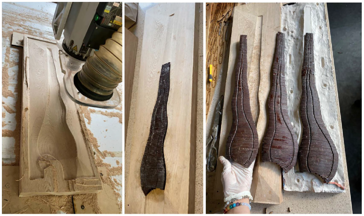
Oak mold of the WLE blade and serial planes agglomerated in MDF.
For resin impregnation, a Smooth-On Star Mold 30 silicone mold is fabricated to replicate the geometry of the WLE blade. The MDF pieces are glued and placed inside the silicone mold. The epoxy is then poured into the mold, covering the material and taking the shape of the mold. Figure 5 shows how the piece looks after being removed from the mold with epoxy and talcum powder, and after applying putty and sanding to correct for imperfections.
WLE blades manufactured with serial planes.
Rotomolding/casting of polyurethane resin
The implementation of epoxy and polyurethane resins is based on affordability, density, weight, price, and other relevant characteristics. However, due to the limited space for thickness in this case study, the rotational movement of the resin becomes challenging as it requires a uniform process. Therefore, manual pouring of the resin is also used, along with the addition of internal serial planes or ribs to provide rigidity and strength in the starting area of the blade.
Methodology and result
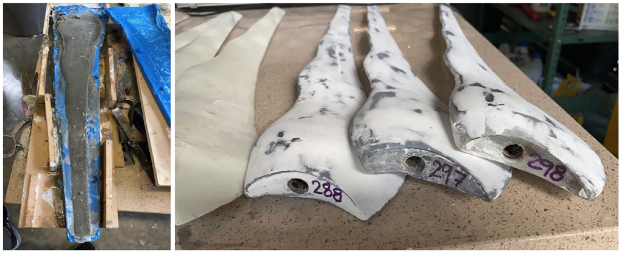
A silicone mold, Smooth-On Star Mold 30, is fabricated to replicate the geometry of the WLE blade. Polyurethane resin is then poured into the mold and the mold rotates for five (5) minutes. The drying time of the polyurethane resin is approximately 3 minutes, so rapid rotation (set at 20 rpm) is necessary to allow the resin to accurately copy the shape of the mold. The wooden support, as shown in Figure 6(a), is inserted at the exact location of the rotor axis. This is done to prepare the silicone mold for the resin casting process and to ensure that the resin does not leak between the mold surfaces. Subsequently, because the mold is not one-sided, there may be some excess material along the line where each side of the mold meets. Also, if a vibrating table is not available, the mold may have bubbles. This excess material and any imperfections are sanded and smoothed. Optionally, the piece can be painted with a light color, such as white, using polyurethane paint to ensure better preservation of the piece, as shown in Figure 6(b) and (c).
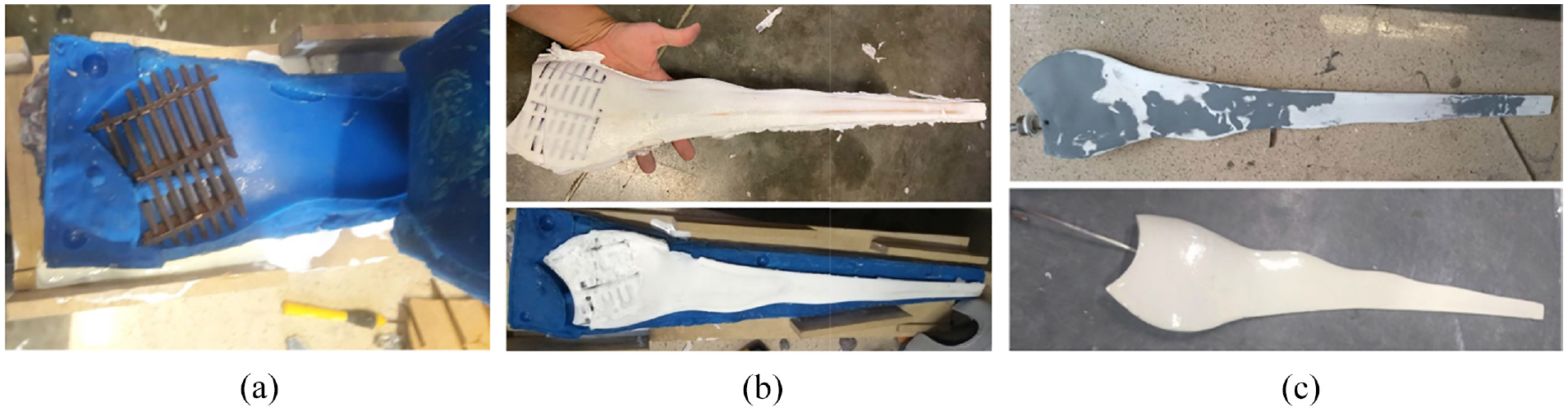
Process of rotomolding/casting resin, final piece: (a) MDF blade with serialized plans, (b) freshly de-molded resin blades, and (c) surface corrections and final finishing.
Tensostructures
Tensile structures comprise a rigid support and a fabric or canvas. Their key feature is their capacity to span extensive areas using limited material. In this instance, an MDF framework with fortified edges is utilized, utilizing mild steel wire and resin. A slight steel rod is inserted inside to offer extra support. Lastly, a serpentine fabric sleeve envelopes the entire structure to adopt the desired shape.
This method was selected because it allows the construction of a blade with the majority of its volume consisting of air, leading to a reduction in weight. Moreover, the low manufacturing costs enable the production of blades at a reasonable price, offsetting any imperfections in the shape with the reduced production costs. The design is built around two shoulders at the two corners of the blade to ensure precision in the shape of the surface and edges, especially in the case of the WLE. Subsequently, there will be an internal base made of oak to endow it with sufficient mechanical properties to withstand fracture and fatigue, with the added advantage of having a low density. In addition, multiple oval-shaped structures will be used to cover the voluminous and concave areas of the front and back segments of the blade. Finally, the blade structure will be covered with 4% serpentine fabric to ensure uniform geometry, while internal hemp threads will be utilized to tension the fabric.
Methodology and result
Three millimeter (3 mm) thick MDF planks are cut and assembled into ribs that roughly follow the shape of the blade, as shown in Figure 7.
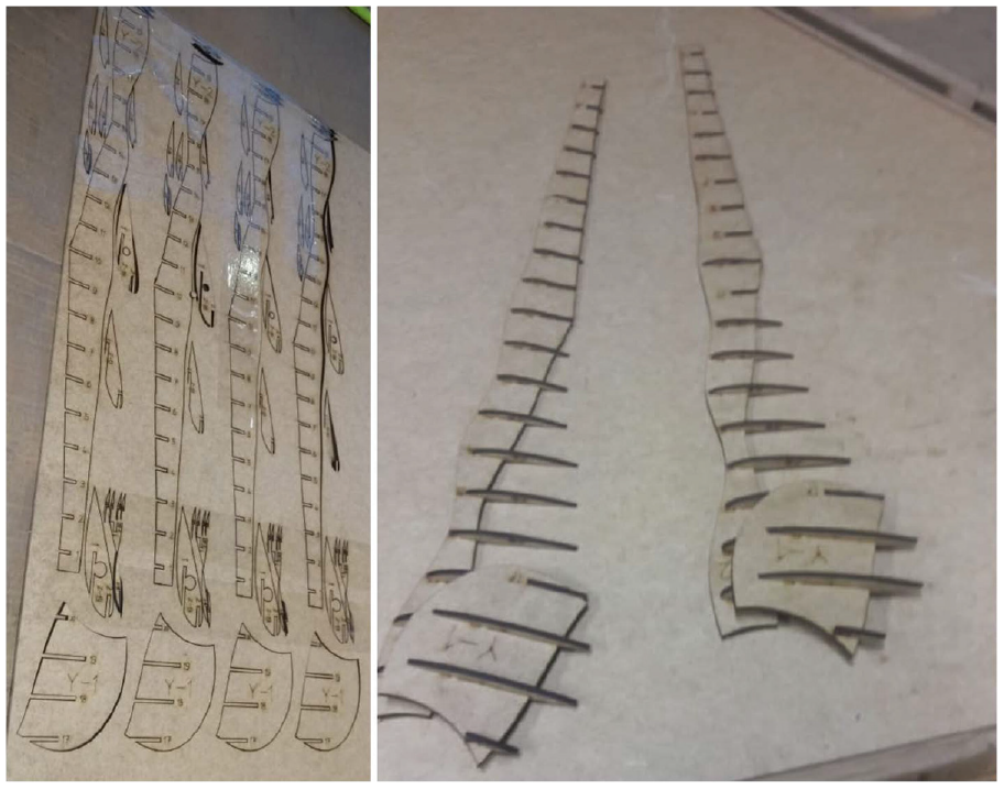
Laser cutting and reinforcement of the ribs of the tensile structures.
The resin epoxy is then poured into the wavy region using a thermoformed mold to create a foundation for the WLE geometry. It is crucial to correctly position the blade inside the mold to ensure that the curves are in the right places during the pouring process. To solve problems with irregularities in the shape of the trailing edge, a mild steel wire is attached to the opposite profile of the poured edge to guide the shape more accurately. The interior is also strengthened with a 3 mm diameter and approximately 15 cm long iron rod placed in the middle of the piece. Once the resin has fully cured and the blade has been thoroughly strengthened, it is time to apply the fabric cover. The sleeve is sewn and the serpentine fabric is positioned at a right angle to the blade’s axis, so that the sleeve can take the intended shape. The edges of the sleeve are smoothed by ironing to ensure a surface that is free of knots or irregularities. Then, the fabric is tensioned and secured in its final position. This process produces a blade with distinctive geometry compared to others. Figure 8 demonstrates a comparison between a blade made with ABS and one created using the tense structure method.
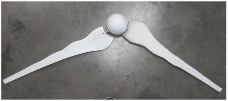
Comparison of ABS blade (left) with tensile structure blade (right).
However, despite its unique design, the blade could be produced quickly and at a substantially lower cost than the standard rate. Additionally, it performs its intended function of turning the rotor once it is installed in the wind turbine. After evaluating its effectiveness, the decision was made to administer a waterproofing treatment to one of the blades to increase the durability of the material in outdoor environments.
Experiment and results
Initially, the analysis begins with a comparison of variables such as Weight, Working Hours, and Price for each of the blade types: ABS 3D printing, polyurethane casting, serial planes + epoxy, and tensestructures. This analysis is shown in Figure 9.
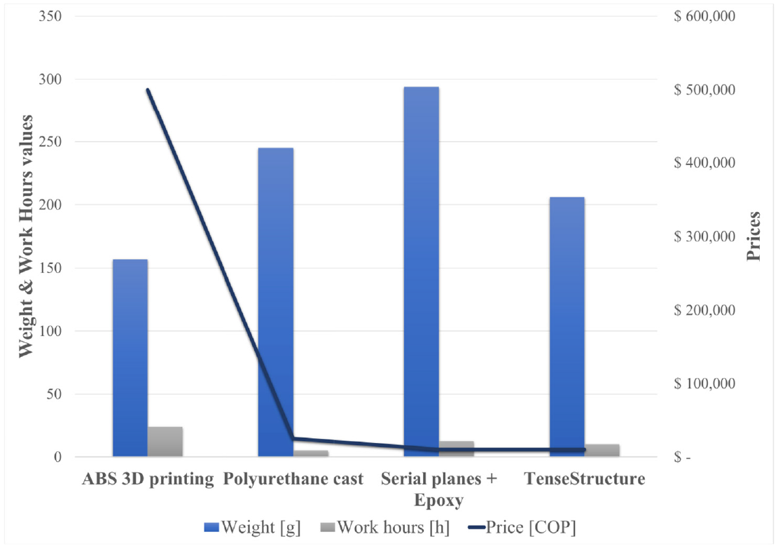
First comparison about weight, work hours and price values.
There is variability in the price range for each of the processes, ranging from 10,000 to 500,000 COP. Similarly, the weights can range from approximately 150 to 300 g, and there is a maximum time limit of 50 hours to work without delays due to mold handling or manual sanding and surface finishing. ABS stands out in terms of price and working hours, with the highest values around 500,000 COP and 24 hours, respectively. On the other hand, Tensestructures offered the least expensive option, costing approximately 10,000 Colombian pesos. Furthermore, polyurethane casting proved to be the most efficient method of completing the job, taking approximately 5 hours to complete.
Figure 10 quantifies the environmental impact using the CES Edupack software. This quantification is based on materials and commercial processes and calculates the weight according to the carbon footprint. The study found that serial planes made of epoxy resin had the highest environmental impact. The energy required for each raw material is also quantified in the software, providing a reference for comparison. It is apparent that serial planes require the most energy at around 25 J, while polyurethane cast requires the least at around 0.5 J.

Second comparison carbon footprint and raw material energy respectively.
The performance validation of the blade is carried out by adapting to a prototype wind turbine at a fixed angle of attack of 39.5°. The prototype was validated for the wind direction and the tests were carried out in a controlled environment, producing average velocities of 2–3 m/s. The goal is to confirm its operability and ability to initiate without any intervention according to the set aerodynamic capacity. A series of experiments was carried out, capturing approximately 8000 data samples within the required time frame to obtain results (two trials of 20 and 40 minutes). The results are depicted in Figure 11.
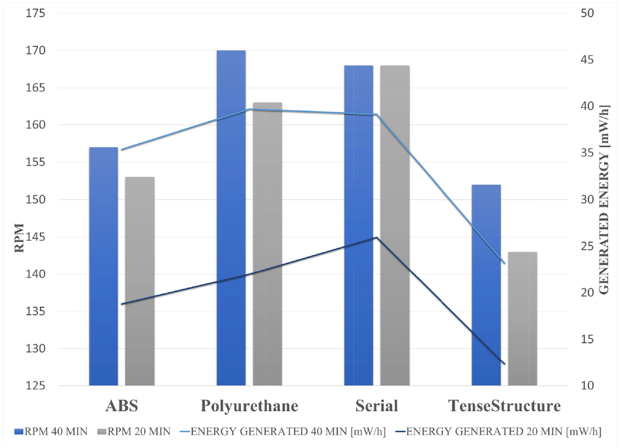
Third comparison in a controlled environment.
The blades manufactured in tensile structures attained the lowest RPM values, recording 143 and 152 during the 20- and 40-minute tests, respectively. On the contrary, the blades made of polyurethane resin casting and serial planes, which had a greater weight, as depicted in the above graphs, had the highest RPM values. Specifically, the former and latter recorded 170 and 168, respectively, in the 40-minute test. Based on the proportional relationship observed between RPM and generated energy, the polyurethane casting and serial plane blades have demonstrated high energy generation levels in the 40-minute test, registering at
It is important to note that estimating the data collection time is vital to ensure better approximations for the listed variables.
Discussions
Various material and manufacturing options are proposed for the manufacturing of HAWT blades, while considering the adaptability and availability of resources. These options consist of composite materials such as carbon fiber or fiberglass, which use processes such as resin transfer molding (RTM) or vacuum infusion. Oak wood can be precision-machined through computer numerical control (CNC) with a choice between section machining or whole-piece production.
Nylon is suitable for CNC machining due to its flexibility, while ABS can be 3D printed by optimizing materials and using chemical finishes to offset any decrease in particular properties with gains in other areas.
In addition, raw materials such as Sisal and jute are worth discussing because of their price, density, and mechanical properties. However, the challenging aspect is how to process these materials, which requires further investigation.
By examining the various options and assessing the distinct characteristics and production capabilities of each material, it is feasible to identify the ideal blend for the WLE scheme, guaranteeing maximum efficiency and cost-effectiveness in the manufacture of WT blades.
Conclusions
The selection of materials and manufacturing processes is critical to the output and effectiveness of wind turbine (WT) blades. This study explores various materials such as ABS, polyurethane resin, epoxy resin, wood and tensile structures, each with distinct features such as density, weight, durability and cost implications. Choosing the right material involves a trade-off between mechanical and manufacturing capabilities and cost effectiveness.
When comparing energy generation, it should be noted that materials and construction processes are the only variables that vary among the different options. All other parameters, including shape, size, blade distribution, and data collection system configuration (including attack angles), are standardized. However, it is essential to recognize that processes and materials can affect the shape and fidelity of the blade.
Initially, ABS was determined to have the lowest density and weight among the materials studied. It weighed 24% less than tensile structures, 36% less than rotomolding/polyurethane cast, and 47% less than serial planes and epoxy, resulting in an average weight reduction of 35% compared to the other materials. However, serial planes and epoxy exhibited the highest weight metrics. ABS took 58% longer to manufacture than tensile structures, with rotomolding/polyurethane casting and similar techniques requiring less time.
In terms of carbon footprint
Regarding the final cost, ABS was found to be costly and difficult to afford, with a significant cost difference of 95%–98% compared to other materials.
There was an average difference of 3% in RPM and 43% in
The impact of material weight on RPM and power generation became apparent, as evidenced by the highest RPM and power generation values obtained during the 27- and 40-minute tests for polyurethane casting and serial planes with epoxy.
During the 40-minute test, the materials with the highest values displayed a 1.41% increase in energy generation and a 1.18% increase in RPM. The rotomolding/polyurethane cast achieved the greatest performance due to energy collection and the inertia resulting from the combination of material-process. These turbine blades demonstrated higher RPM and
The aerodynamic surface accuracy and precision of the blades also contributed to consistent energy generation, with weight being the primary factor. Tensile structures proved inadequate for small-diameter blade applications due to difficulties in handling tension elements and the more laborious and less precise production process, which had a direct impact on geometry fidelity. However, they may be suitable for larger diameter wind turbine blades, potentially leading to more significant benefits.
This study emphasizes the importance of meticulously selecting materials and manufacturing processes to optimize the performance, efficiency, and cost-effectiveness of WT blades. Every alternative comes with its benefits and drawbacks, underscoring the necessity of a tailored strategy for each situation, taking into account the required turbine size, site, budget, and environmental factors.
Footnotes
Appendices
In section of composites, the following tables present the matrix materials, focusing on resins, and the reinforcement materials, focusing on fibers, used in composites as shown in the following:
The research conducted serves as the basis for a more specific material selection, where a survey of small HAWTs identified the materials commonly used for this application, as shown in Appendix Table 3.
Materials chosen in the first Ces Edupack filter.
Table that analyzes the main properties of each of the materials in a in a refined search for materials in a refined search for materials (Level 3 CES Edupack):
Acknowledgements
The authors would like to thank Sara Lopez Castaño and Alejandro Martinez Giraldo who participated in the construction of the prototypes and the work team of the engineering and design research group (GRID).
Declaration of conflicting interests
The author(s) declared no potential conflicts of interest with respect to the research, authorship, and/or publication of this article.
Funding
The author(s) received no financial support for the research, authorship, and/or publication of this article.