
Abstract
Direct hydration of cyclohexene to produce cyclohexanol is the industrial process with a lower raw material cost but with a quite expensive process. Large energy consumption is consequence of large cyclohexene recycle related with its unfavourable chemical equilibrium. This study corroborates that the Asahi process is a good candidate for intensification avoiding the cyclohexene recycle. Rigorous simulation shows that a single reactive distillation column, with a side decanter, operated at total reflux, allows overcoming the chemical equilibrium limitations as the product is continuously collected by the column bottoms and the heat of reaction is directly used to separate the product by distillation. The novel process is studied and compared to the classical Asahi process. An energy comparison with the available processes proposed in the literature is performed. Therefore, achieving more energy-efficient processes leads to lowering their environmental impact, thus decreasing the carbon dioxide emissions. Applying the proposed methodology for cyclohexanol production, more than 67,000 t CO2/y emissions can be avoided compared to the nowadays used classical process, thus the potential savings applying process intensification to the chemical industry are very large and worth further investigation.
Keywords
Introduction
Energy-related carbon dioxide emissions account for about 98% of U.S. CO2 emissions. 1 Distillation systems are energy-intensive processes and contribute significantly to greenhouse gases emissions. Distillation is responsible for a significant amount of the energy consumption of the world’s process industry. Only in USA, there are 40.000 distillation columns with a consumption around 160 MW (5·1018J/y) 2 what produces around one thousand million of metric tons of carbon dioxide each year. 3 Any small improvement in distillation process efficiency has a great impact on greenhouse gas emissions and process intensification has a significant energy saving potential.
The improvement of existing processes, 4 or the selection of the most energy-efficient process 5 to produce polymers allows to decrease the cost and environmental impact of their production, decreasing the carbon dioxide emissions. Glass reinforced polymers, i.e. fibreglass, are very strong and relatively lightweight, which makes them suitable to produce large blades for marine aero-generators applications or nylon is a very resistant fabric of air filter bags for dust collectors. Cyclohexanol is an important bulk chemical, for instance, it is used to produce adipic acid which is the monomer for nylon production. In 2018, the U.S. production volume of polyamide nylon amounted to a total of approximately 595,000 t. 6 By 2017, global polyamide fibres production was 5.7 million t. 7 Nylon comprises 20 per cent of the world’s manufactured fibre production, which in turn is almost half the total of overall fibre production. 8
There are three main industrial routes to produce cyclohexanol: cyclohexane oxidation, phenol hydrogenation and cyclohexene hydration. Cyclohexanol mixed with some cyclohexanone by-product is produced by oxidation of cyclohexane in a process with safety concerns, e.g. Flixborough accident in England (1974). Novel catalysts can oxidise cyclohexane to cyclohexanol and cyclohexanone using alternative oxidants to O2, e.g. metal oxodiperoxo complexes, 9 O3 in liquid CO, 10 tert-butyl hydroperoxide 11 or H2O2. 12 Although process promoters increase the yield, 13 low yields are achieved compared with O2. 14 Some catalysts with higher conversion rates produce lower selectivity towards cyclohexanol. 15 Cyclohexanone by-product can be converted to cyclohexanol by catalytic hydration. 16 Some other studies on this process focus on improving the catalyst, e.g. hollow Mn-ZSM-5 zeolite, 17 NH4 on ZSM-5 zeolite, 18 Zr ferrites, 19 manganese porphyrins, 20 etc.; or the reaction media, e.g. molybdenum complexes in acetonitrile, ionic liquid and supercritical CO2 media. 21 Besides the safety concerns, cyclohexene as a feedstock used in the direct hydration process is relatively more cost-competitive compared to the cyclohexane. 22
In 1988, the direct hydration of cyclohexene by Asahi Chemical from Japan was considered a process less economically attractive than the phenol-based cyclohexanol process, but the lower cost of cyclohexene allowed a cheaper cyclohexanol product. 23 The phenol process is still under study improving the catalysts and operation conditions, e.g. Ni-Co on biochar, 24 Ni-CNT, 25 Ni-Co on Carbon/ZrO2 nanoparticles, 26 Ni-Co on silica-titania composite, 27 etc. Hydrodeoxygenation of lignin-derived phenolics such as guaiacol as renewable raw material to produce cyclohexanol have gained increasing research attention in recent years, e.g. ruthenium on alumina, 28 nanoporous nickel, 29 Pd/Fe, 30 Ni–ZrO2 on CMK-3 carbon, 31 electrocatalytically, 32 etc.
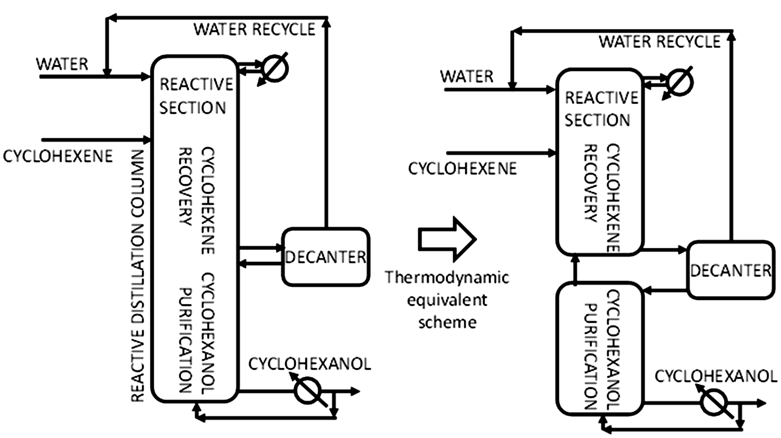
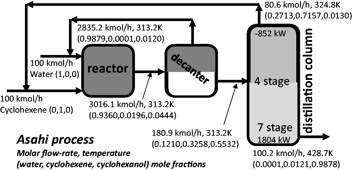
The direct hydration of cyclohexene is the industrial process producing cyclohexanol from cheaper raw materials and this study focuses on this process. The direct hydration of cyclohexene is performed in the Asahi process, where cyclohexene is hydrated over a heterogeneous catalyst in a slurry reactor. The extent of the reaction is very limited by the equilibrium constant. A large excess of water reactant is used in the reactor to push the reaction forward. The excess of water is recovered in a decanter and returned to the reactor again. The organic phase of the decanter, consisting of the cyclohexanol product and the non-reacted cyclohexene, is fed to a distillation column where the produced cyclohexanol is recovered by the bottoms. Due to the significant difference on boiling points between cyclohexene (83 °C) and cyclohexanol (162 °C), both compounds are easily separated by distillation and the cyclohexene recovered by the distillate is returned to the reactor. The decanting operation for the separation of non-reacted water does not consume energy, however, a large flow rate of non-reacted cyclohexene is evaporated in the distillation column due to the low conversion in the reactor, involving a large energy consumption (Figure 1(a)).

Novel intensification of the Asahi process: (a) Asahi process, (b) reactive distillation column with side decanter.
The reaction is exothermic, and some authors tried to intensify the process proposing the use of a reactive distillation column. In this way, the continuous product removal from the reaction media shifts the reaction to total conversion, avoiding the recycle of non-reacted cyclohexene and the reaction enthalpy is directly used in the distillation providing savings on the reboiler duty. A hybrid reactive distillation column with a non-reactive section at the bottoms 33 was pointed out to be suitable to produce cyclohexanol by direct hydration of cyclohexene. In case that cyclohexane would be present in the cyclohexene feed, this would be recovered pure at the distillate. Some studies about the use of reactive distillation for cyclohexene dehydration are in continuous 34 and in batch using formic acid as reactive entrainer, 35 1,4-dioxane 36 as solvent to increase the solubility of cyclohexene in water, isophorone 37 as extractive agent (the vapor liquid equilibrium data for this system is available 38 ) 16 . A side reactor 39 to the reactive distillation column can also be used. Despite using reactive distillation, an excess of water is helpful to take advantages of the phase split at the output streams. 40 The studies that provide an energy consumption estimation are further discussed and compared in the results section.
Marchante et al. (2019) 41 proposed a novel reactive distillation process with a side decanter, where the excess of water is maintained at the upper reactive section (Figure 1(b)). The compositions profiles in the upper sections of this reactive distillation column with water excess generate a different distillation region than the lower section profiles of the column rich in cyclohexanol. The use of the side decanter allows crossing the boundary line that divides both distillation regions in the residue curve map, linking both column profiles. Therefore, the cyclohexene hydration and cyclohexanol separation both become feasible in a single reactive distillation column, avoiding the addition of any third compound. The column operated at total reflux and atmospheric pressure is divided in three sections. The first section at the top of the column is where the reaction takes place. Water is fed at the top of this section at the first column stage and the cyclohexene at the bottoms of this first section. Both reactants flow in counter-current: the heavy reactant (water) flows downwards and the light reactant (cyclohexene) flows upwards. The second section is located between the cyclohexene input and the side decanter. This section aims to return part of the non-reacted cyclohexene to the first section and the non-reacted water is returned from the decanter to the first stage again. As water is mainly flowing down the column, it does not consume energy and an excess of water is used, being the main compound in the liquid upper column sections. Finally, the last section is aimed to purify the cyclohexanol. Cyclohexene is the main compound of the vapour phase except at the bottom stages where cyclohexanol is the main compound.
Figure 1 compares the novel intensified process with the Asahi process, showing their analogies. The same sections are identified in both processes, but the intensified one does not follow a sequential approach: reaction, decanter for water recycling, distillation for cyclohexene recycling and cyclohexanol purification. The synergy between reaction and separation provides some advantages: the continuous product recovery at the column bottoms allows to overcome the chemical equilibrium and the enthalpy of reaction is directly used in the distillation. However, some other points are also beneficial such as fewer units, reactant cyclohexene recycle stream is avoided, less piping, space-saving, larger catalyst lifetime (organic heavy compounds in cyclohexene feed would not reach and deactivate the catalyst situated above this feed), increased process safety as the cyclohexene is present with large amounts of water, etc.
The lower cost of the cyclohexene as raw material makes its direct hydration more cost-competitive than the alternatives processes to produce cyclohexanol, although the process is not very efficient and less economically attractive. Several attempts to increase its efficiency by process intensification are available in the literature, but without a clear advantage on the reference industrially used process, i.e. the Asahi process. This study aims to propose an intensified process requiring less process units and with a lower energy consumption than the Asahi process. A novel process scheme proposed 41 using a reactive distillation with a side decanter is assessed. Cyclohexanol is an important bulk chemical and any small decrease in its production energy consumption provides an important decrease in carbon dioxide emissions.
At our knowledge, the process scheme proposed (a reactive distillation column linked with a side decanter, with side-draw streams) is a novel process scheme, and therefore a detailed Method section is presented to be applied to other case studies. The structure of the Method chapter consists of several sections dedicated to: the description of the thermodynamic model and its parameters (2.1), the input data for the Asahi process (2.2), the intensified process (2.3) and a section indicating the steps required to reach the simulations’ convergence to near-optimal conditions. The results obtained for the Asahi process (3.1) and the intensified process (3.2) are compared with the previous literature results about cyclohexene hydration (3.3.). Finally, the Conclusions summarise the main findings and results (4).
Method
Cyclohexanol is industrially produced by direct hydration of cyclohexene as indicated in the Asahi patent since 1990. Process intensification combining in synergy several unit operations into a single unit allows improving existing processes for energy consumption and capital costs. The Eastmann Kodak process is a successful typical book example, but further successful examples showing intensification advantages are required to spread its industrial use that is still rather scarce. Distillation is a very energy-intensive unit and process intensification has a great potential to reduce its energy consumption and the associated greenhouse gas emissions.
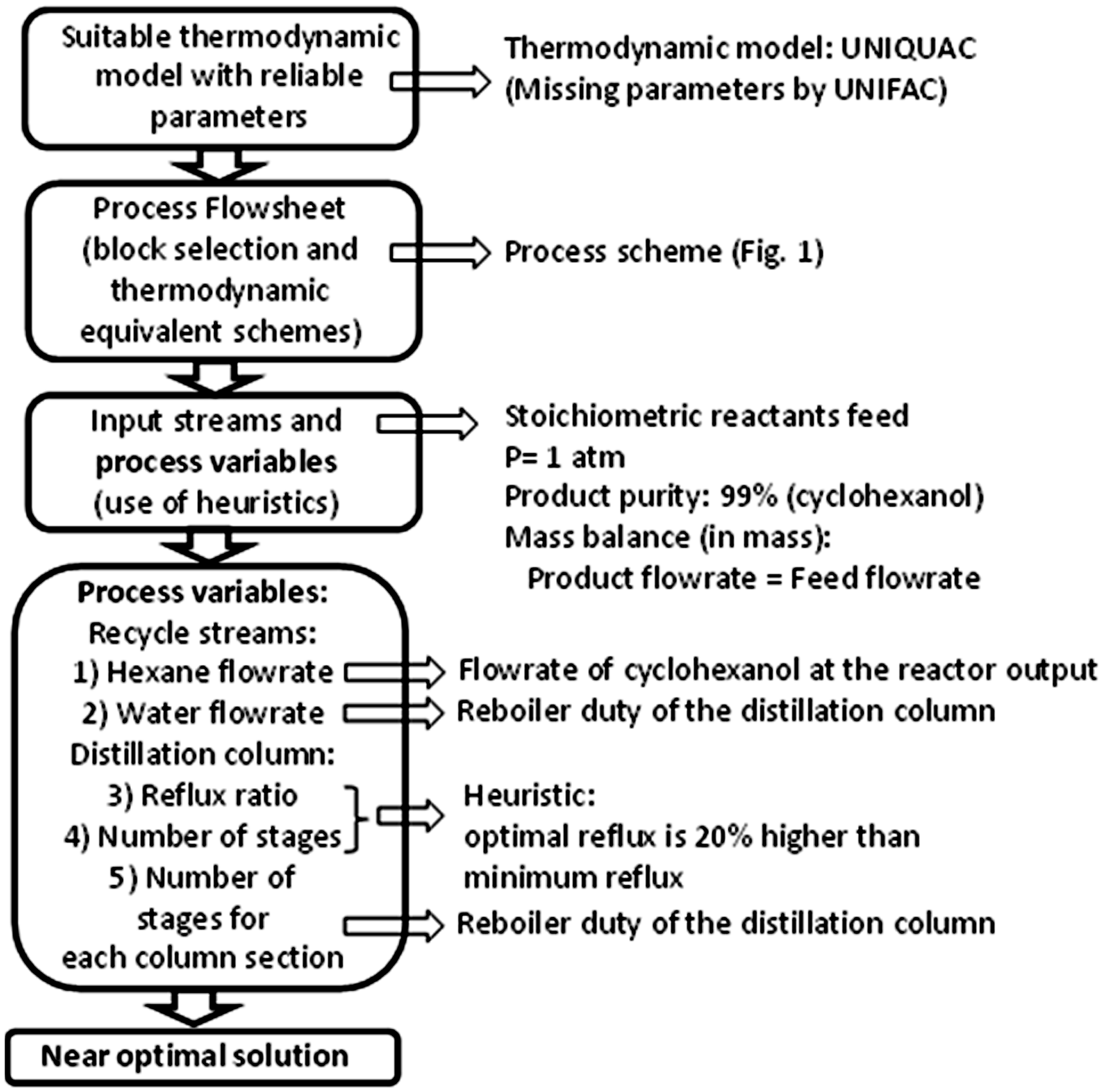
Traditionally, each unit operation was performed in a different process unit. Combining several unit operations in synergy in the same process unit is known as process intensification. Some industrials examples are proving that the efficiency of the process can be significantly improved, but a large number of successful examples are required to make process intensification widespread in the industry. This section provides the guidelines of how to simulate the Asahi process and the novel proposed process (Figure 2) rigorously. The simulation assures the conservation principles, e.g. mass and energy balances, but not the reliability of the results, which depends on a suitable thermodynamic model with reliable parameters. By default, the simulation software assumes ideal mixture for the missing parameters. Parameters regressed from experimental data are preferable than estimated parameters, but the estimated ones are preferable than the coarse assumption of ideal mixture. The next step is the representation of the process flowsheet in the simulation environment. Many classical unit operations are readily available in the simulator, including different unit (block) models according to the data available and the kind of unit. Some intensified unit operations are not available and are represented combining different individual units into a thermodynamically equivalent scheme. Once fixing the input streams to the process and the degrees of freedom of each unit, the simulator proceeds with a sequential assessment of the units and iterating when recycle streams are present, until fulfilling the conservation principles. For a more robust convergence, some output streams must be specified according to the overall mass balance. The units variables are fixed according to rules of thumb to provide a near optimal solution. The process variables provide a flat minimum cost region and therefore, the variables value’ variations in this flat minimum do not affect appreciably the overall costs. For instance, a rule of thumb indicates that the optimal distillation column reflux is around 1.3 times the minimum reflux. The simulation of a distillation column with a large number of stages (enormous investment costs) allows reaching the minimum reflux (low operating costs). Then the number of stages is decreased until fulfilling the heuristic. Further optimisation of the variables that minimise the energy consumption (operating costs) without increasing the investment costs is necessarily performed, e.g. distillation column feed stage.

General block diagram of the resolution procedure.
Thermodynamic model
The thermodynamic model selected in this work is UNIQUAC for its suitability for systems with phase split. The vapour-liquid equilibrium data for the compounds involved in the direct hydration of cyclohexene to cyclohexanol 38 were determined and regressed at 500 kPa and also the Antoine parameters for the vapour pressure. However, the mixture 38 also contains isophorone (to generate a soluble mixture) and the regressed UNIQUAC parameters are not representative for the low solubility of cyclohexene and cyclohexanol in water, as many authors experimentally determined it. Therefore, as in the present study is taken advantage of the phase split to cross the distillation boundary without requiring any third compound, these regressions are not applicable. The vapour-liquid equilibrium data for the mixture cyclohexene/cyclohexanol is not available in the simulator database. The regressed parameters 38 for the binary mixture cyclohexanol/cyclohexene present a pinch zone close to pure cyclohexanol, while the UNIFAC estimation indicates a natural separation of cyclohexanol from its cyclohexene mixture. The regressed parameters 38 are useful for the authors’ purpose but not to simulate the Asahi process due to this unfavourable pinch region and the absence of phase split. Therefore, the default UNIQUAC model parameters readily available in AspenPlus® v10 simulator, estimating the missing parameters by UNIFAC, has been selected.
There is intensive research for improving the catalysts used for cyclohexanol production, mainly for cyclohexane oxidation, but also for cyclohexene hydration, e.g. ZSM-5 aggregates 42 or trifluoroacetic acid. 43 To provide a general study independent of the catalyst used, a mixture at chemical equilibrium is assumed (Gibbs energy minimisation). Although the chemical equilibrium cannot be attained, usually it is approached; furthermore, it provides the minimum energy attainable for reactants recycle. AspenPlus® v.10 is used to perform the rigorous process simulations. The simulation flowsheet of both the classical Asahi process and the novel process proposed uses rigorous Radfrac blocks for the columns (MESH model), and a calculation basis of 100 kmol/h of cyclohexene crude feed, with a stoichiometric amount of water crude feed (100 kmol/h). All the process units operate at atmospheric pressure.
Input data for the simulation of the Asahi process
For the simulation of the Asahi process, a stoichiometric equimolar mixture of cyclohexene and water is fed to the process, i.e. 100 kmol/h of each pure reactant. The process has two crude feed streams and a single output stream: the cyclohexanol product stream. To fulfil the overall mass balance of the process, the column bottoms to separate the cyclohexanol must be fixed at 10,016.07 kg/h. The overall balance is fulfilled in mass units by this fixed value but for mole units the value depends on the reaction conversion: two moles of reactants produce one mol of product. The RGibbs reactor does not require any input data besides the pressure and temperature and calculates the output stream according to Gibbs energy minimisation. The reaction conversion and phase split are promoted at low temperatures and vapour phase is avoided due to to the boiling point of the mixture compounds. Therefore, reactor and decanter are at 40 °C, temperature reasonably attainable by refrigeration water. A rigorous distillation column Radfrac is used.
The recycled flow rate of water and cyclohexene (ENE) are the two process variables to be assessed first. These process variables’ values that minimise the reboiler requirements are determined. The number of stages of the distillation column is fixed to a considerable value, i.e. 80 stages and feed is placed in the middle of the column. To assure that enough cyclohexanol (NOL) is fed to the distillation column to reach the required purity, a process design specification is provided: the recycled ENE flow rate varies to assure a distillation column feed of 100 kmol/h NOL (according to the crude feed reaction stoichiometry). A significant excess of NOL involves large energy consumption as the NOL in excess is collected by the distillate and recycled to the reactor. However, a small excess would be necessary for control purposes. Another design specification for the distillation column is setup, varying the distillation reflux ratio until a value that allows a bottoms purity of 99% NOL (wt). The number of stages is fixed according to the rule of thumb that the reflux flow rate is around 20% higher than their minimum value assimilated to the value obtained with a large number of stages. The feed stage is determined by a sensitivity analysis to minimise the reboiler duty.
Input data for the simulation of the reactive distillation column with a side decanter
Marchante et al. (2019) 41 proved that a reactive distillation column of only 11 stages and a side decanter could produce high purity cyclohexanol. However, this novel process was not analysed and required a large energy reboiler duty because it was not in a near-optimal solution. In the present study, the cyclohexanol purity is fixed at 99% weight, and the process analysed.
Usually, distillation column purities are adjusted according to the reflux ratio and an output stream, i.e. distillate or bottoms flow rate. This column is operated at total reflux, and the overall mass balance establishes the bottoms flow rate. Therefore, the variables available to be adjusted are similar to the Asahi process, except the reflux ratio of the distillation column: the liquid flow rate from the side decanter to the top of the column (recycled water), crude cyclohexene feed stage, side decanter stage placement and overall number of stages. In this case, there is not any more an external recycled cyclohexene stream, but the non-reacted cyclohexene is internally recovered at the lower stages of the column and returned to the reactive stages (recycled cyclohexene). It is assumed that the entire liquid flow is deviated from the column to the decanter. Initially, a large number of stages is considered to find the minimum energy requirements. As in the Asahi process, there is an internally recycled flow rate of cyclohexene from the section below to the decanter to the section above the decanter. It must provide a molar flow rate of cyclohexanol from the decanter to the lower section of the column of 100 kmol/h cyclohexanol, so that the product stream can have the required purity. The recycled water flow rate is used to minimise the reboiler duty as in the Asahi process. Once reaching the minimum energy consumption, in a second step, a near-optimal solution is obtained, decreasing the number of stages.
The system is rather simple to simulate, a single reactive distillation column with a side decanter collecting all the liquid stream flowing down the column. As the reactive distillation with a side decanter is a novel system not previously simulated in literature, the rigorous simulation of the process flowsheet in AspenPlus® needs the use of a thermodynamically equivalent process flowsheet (Figure 3) due to non-availability of necessary process variables in the simulation software. Therefore, the reactive distillation column is divided into two distillation columns interconnected: the lower column has no condenser, and the upper column has no reboiler. When feeding the vapour leaving the top of the lower column to the last stage of the upper column and the liquid leaving the bottoms of the upper column to the first stage of the lower column, a scheme with two distillation columns equivalent to one single column is obtained. In this case, the column must be divided to introduce the side decanter and to be able to define the flow rate of cyclohexene present inside the column.
Process flow sheet implemented in AspenPlus® to simulate the reactive distillation column with side decanter.
Notice that although the intensified and the Asahi processes have certain similarities, due to intensification, many variables in the Asahi process are not available any more, i.e. reaction temperature and decanter temperature depend on the column temperature profile (decanter defined as adiabatic).
Near-optimal simulation procedure
The first steps of the Method implementation are the definition of the thermodynamic model, the representation of the process flowsheet based on the process scheme and the choice of simulation blocks proposed according to the available data, input streams and desired output streams purities (Figure 2). This section provides some hints to consider when converging the system to a near-optimal solution.
A single distillation column operated at atmospheric pressure, with a defined feed stream, has four degrees of freedom, e.g. reflux, number of stages, feed stage and bottoms flow rate. For the assessment of the minimum reflux, a large number of stages is assumed above and under the feed stage. The two variables remaining, reflux ratio and bottoms flow rate, are used to define the distillate and bottoms purities. In the process schemes proposed in this study, the distillation bottoms flow rates become fixed, fulfilling the overall process mass balance. The reflux ratio, the only variable remaining, is also fixed to a large value.
Once established the temperature of the decanter and the Gibbs reactor, no other variables are required by the simulator for the Asahi process. A challenging issue to overcome of process simulators is dealing with compounds trapped inside the system that generate different degree of freedom: the flow rate of water and cyclohexene (Figure 4). In this case, a SEP block and a Heater are added to cut the stream. The SEP block separates the trapped reactant, whose flow rate coincides with the feed flow rate to the heater, according to an overall process mass balance. The goal is the manipulation of this variable, without affecting the stream proprieties due to this artifice: the other compounds are not affected, and a Calculator block is used to transfer the stream temperature input to the output stream. A heater is used to transfer the temperature information, not to change the temperature of the stream. This artifice is not physically present in the process but is needed to define these variables. The same procedure is applied to the intensified process, at the aqueous output stream of the decanter and the vapour stream circulating from the lower column to the upper column. In this last case, a calculator is not needed because the stream is at its dew point.
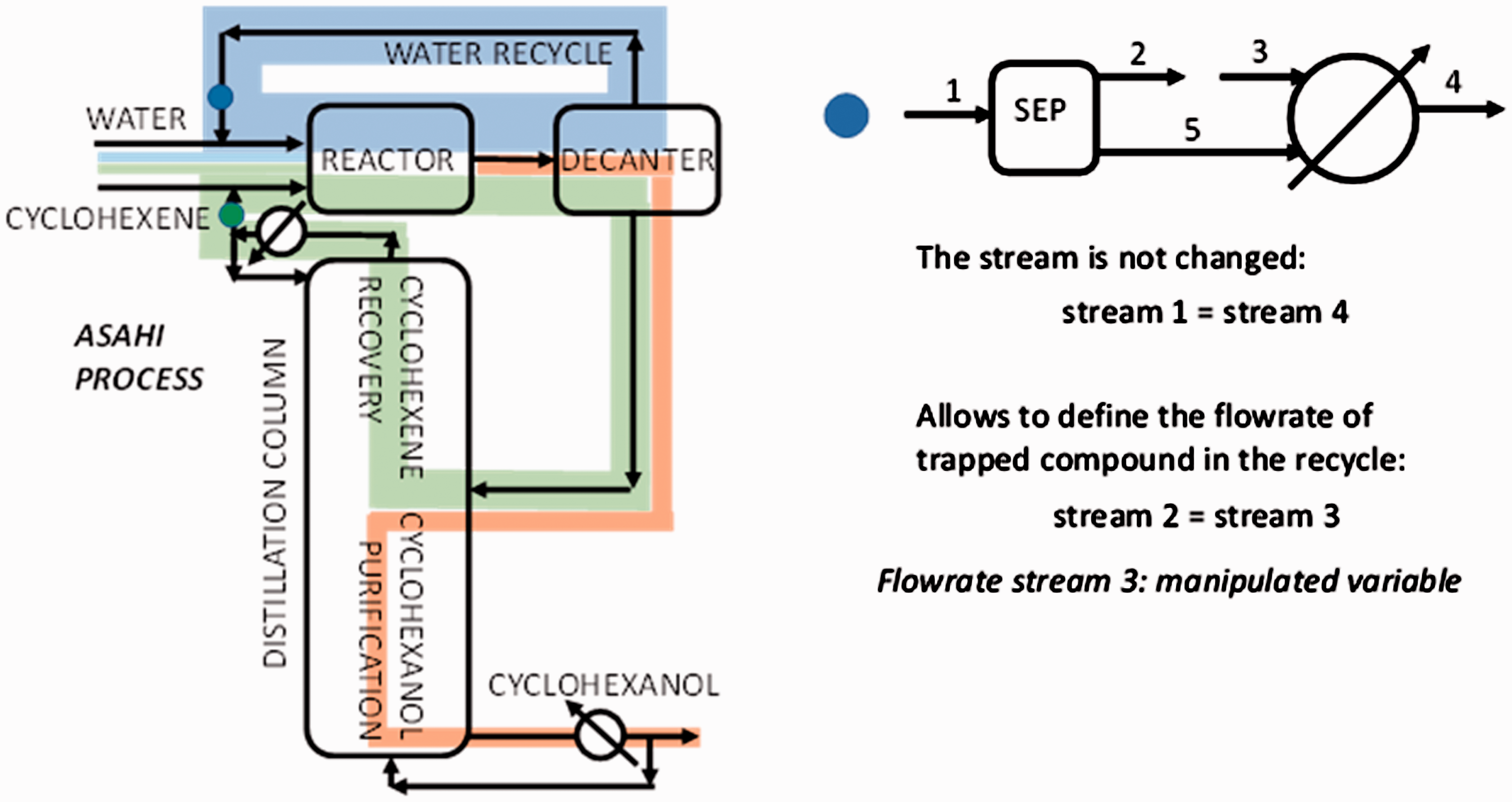
Trapped compounds inside the Asahi process and artifice to manipulate them.
As now the variables are available, they can vary towards a near-optimal solution. The variables are assessed fixing the unknown variables at an enormous value that later is modified according to heuristics o minimising the energy consumption (Figure 5). As the flow rate of water is unknown, a large value is used to assure being in high excess. If the recycled flowrate of cyclohexene is too low, then not enough cyclohexanol product is generated in the Asahi process reactor. In this case, the cyclohexanol that is not present at the distillation column feed cannot be recovered at the column bottoms, therefore hindering the product purity. On the other hand, a large flowrate of cyclohexane generates a larger flowrate of product at the column feed, that overcomes the value fixed to be recovered at the bottom’s column stream, provoking its recycling and trapping into the process. A large flowrate of product trapped in the process increases unnecessarily the process costs. Therefore, a DesignSpec specification is used to vary the flow rate of recycled cyclohexene to produce a mass flow rate of product at the reactor output slightly higher than the mass flow rate of crude feed of cyclohexene and water. In this case, an almost pure product is collected by the column bottoms. According to the heuristic, 44 the recycled streams purity optimum is quite high (around 99%) to decrease the costs derived from recycling.
Block diagram of the resolution procedure applied to the cyclohexanol process.
The next variable to optimise is the reflux of the distillation column. A design specification varies the reflux ratio of the distillation to collect the cyclohexanol at the desired purity. A sensitivity analysis of the water recycled flow rate provides a reasonable value for this parameter. The last variable to optimise is the number of stages. The calculated reflux corresponds to a value close to its minimum and, according to the heuristic, 45 the optimum reflux is about 20% higher than the minimum. The number of stages is decreased until this condition is fulfilled. The feed stage is optimised based on the fact that for a fixed number of stages, there is a feed stage that minimises the energy consumption. 46 The same procedure is applied to the intensified process.
Results
Rigorous simulation of the Asahi process
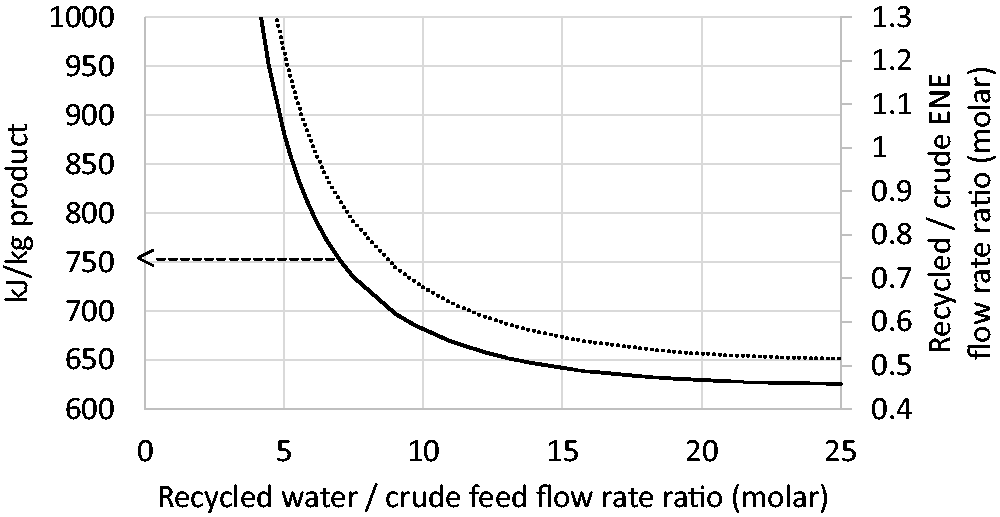
With the assumptions indicated in the Methodology section, the first variable to be assessed is the flow rate of recycled water using a large number of stages in the distillation column (Figure 6). A direct relation between the flow rate of cyclohexene recycled and energy consumption is corroborated. An excess of water pushes the reaction towards product formation and decreases the cyclohexene recycled and the energy consumption of the distillation column reboiler. However, the reboiler duty savings become smaller as the flow rate of water increases. A considerable water flow rate increases the pumping costs and the piping, reactor and decanter sizes and costs. This kind of function shape produces a flat cost region in the elbow zone and assuming that the optimum is around 20% the minimum energy consumption, then the recycled water flow rate becomes 7 times higher than the crude feed flow rate. For 100 kmol/h of each crude reactant (cyclohexene and water) then 1,400 kmol/h water recycled are required. Under this assumption, there is an energy consumption of 752 kJ/kg of product collected by the column bottoms. The reflux ratio required in the column for 80 stages is of 0.058, which must be a value close to the minimum reflux ratio due to a large number of stages used. The number of stages is decreased according to the rule of thumb until reaching a required reflux 20% higher than the minimum reflux, i.e. around 0.07. The rule of thumb is fulfilled in a 9 stages column, with the feed located on stage 6 and with an energy consumption of 756 kJ/kg product (Figure 7).
Influence of the recycled water flow rate in the Asahi process.
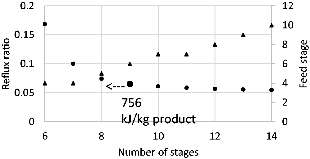
Distillation column design for the Asahi process.
In a scenario where energy saving has a higher weight, the amount of recycled water could be duplicated, decreasing the energy consumption quite close to the minimum. The minimum reflux ratio becomes 0.026 and the optimal according to the rule of thumb is 0.033. The rule of thumb is fulfilled in a 7-stages column, with the feed located on stage 4 and with an energy consumption of 648 kJ/kg product. The converged process flowsheet with the stream flow rates and molar fractions is presented in Figure 8. The temperature and cyclohexanol mole fraction increase monotonically from distillate to bottoms, while the cyclohexene mole fraction increases from bottoms to distillate (Figure 9). The water is mainly present in the vapour phase together with the cyclohexene along the column. The most volatile compound with a higher presence in the vapour phase is cyclohexene except in the first stage where pure water is fed and the last stage where pure cyclohexanol is collected.
Asahi process flowsheet.
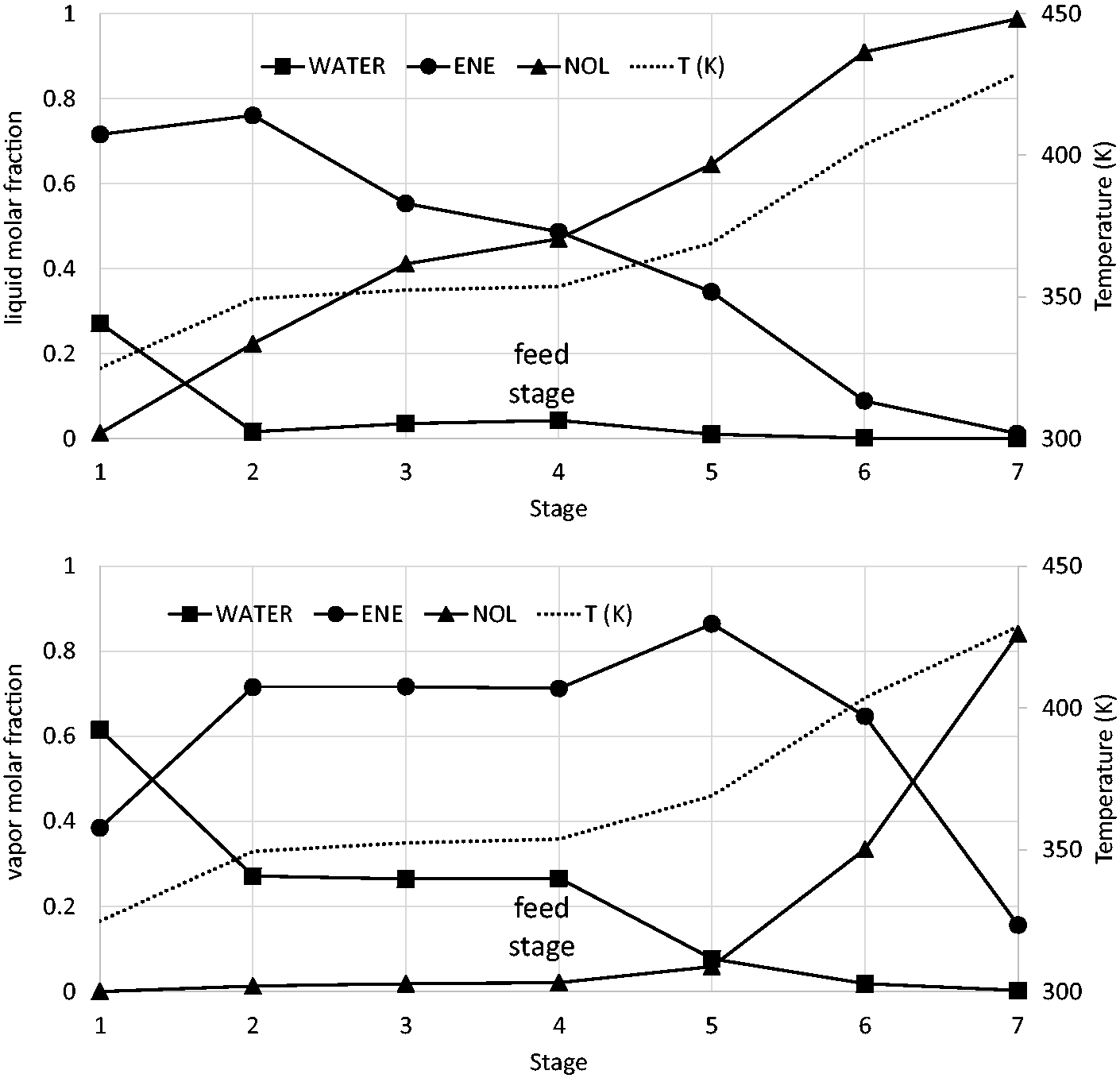
Mole fraction column profiles of the Asahi process.
Rigorous simulation of the intensified process
When all the recycle streams are connected, a flow rate of mixed cyclohexene of 19.4 kmol/h (molar ratio of internal and crude flow rates of cyclohexene of 0.194) is converged and the bottoms mass fraction of cyclohexanol is 0.99 with a reboiler duty of 1,431 kW (514 kJ/kg product). Compared to the Asahi process, the recycled cyclohexene is around 60% lower, and this leads to energy savings of 20%. Figure 10 shows the influence of the water flow rate on energy consumption. A sudden decrease of the energy consumption is produced until recycled water versus crude feed molar flow rate ratio of 6 (the equivalent point for the Asahi process requires a ratio of 14). For higher water flow rate ratios, the energy consumption is quite similar; meanwhile, the column diameter would increase the column costs. The next step is to eliminate the separation stages of the profile where the composition is not changing. Sometimes a flat composition profile is observed in the reactive stages, but they are required for reaction purposes. Figure 11 shows that most of the column stages are unnecessary.

Influence of the recycled water flow rate in the intensified process.
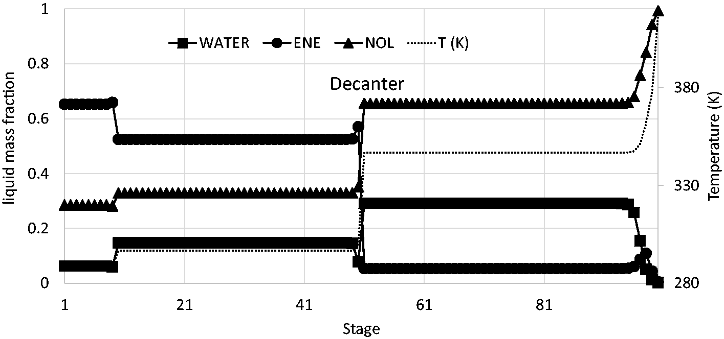
Mass fraction profile for the intensified column with a large number of stages.
As for the Asahi process, with around 7 stages is enough to separate cyclohexene from cyclohexanol. Three reactive stages are chosen as proposed 41 and there are two non-reactive stages between the reactive section and the decanter. Therefore, although the water flow rate is quite different from Marchante et al. (2019), 41 the number of stages of each column section is similar. Figure 12 shows the proposed near-optimal flowsheet with an energy consumption of 1,525 kW (548 kJ/kg product) and Figure 13 illustrates the molar column profiles. Cyclohexanol molar fraction and temperature follow a similar monotonic increase along the column from the distillate to the bottom with a sudden change at the side decanter. As expected, a sudden decrease of the water molar fraction occurs at the side decanter stage, meanwhile, the cyclohexene presents a maximum at this point. The water molar profile also presents a maximum but close to the column bottoms at stage 10. Cyclohexene is the main component of the vapour phase, except close to the column bottoms where the water is the main compound. It is interesting the rather low temperature attained above the decanter where the reaction enthalpy is generated; this fact can be attributed to the large amount of water circulating in the column which acts similar to a refrigeration water tower. Low temperatures are favourable for the chemical equilibrium and phase split in the decanter. The effect on reaction kinetics is out the scope of the present study, but it is an important aspect to be studied.

Intensified process flowsheet.
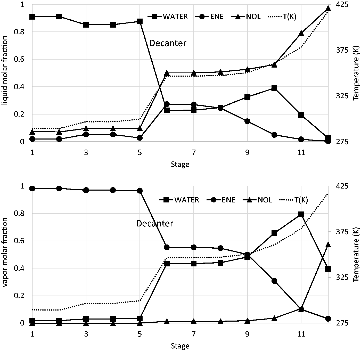
Mole fraction column profiles of the intensified process.
A value of 20% energy savings is not a large value but considering that distillation is the unit operation most used to separate liquid mixtures, a decrease of 20% on USA distillation columns would represent a decrease of 200 million of metric tons of CO2 emitted. Intensified processes, where reaction and separation take place in synergy, must substitute the classical conception of a reactor followed by a train of separation units to recycle the reactants and purify the products as most of the energy of chemical processes is mainly consumed in the distillation column’s reboiler.
Comparison of the proposed process scheme with the literature
The research and proposal of novel processes change the state of the art continuously. The companies to be competitive and protect the environment should use the alternative processes more energetically efficient and less polluting in their operation and in their potential risk of pollution in case of an accident. In this section, a literature review of rigorously simulated processes to produce cyclohexanol by hydration of cyclohexene is provided.
For an organic mixture with 12% wt cyclohexanol 47 is fed to the distillation column of the Asahi process, a very large number of stages, i.e. 100, is defined in the column simulation to find the minimum energy consumption. It was achieved a consumption corresponding to 3,174 kJ/kg cyclohexanol with a purity of 99% (7.5 MW for a production of 100 kt/y). In the present study, it has been demonstrated that with a large excess of water, i.e. 28 times the crude feed flow rate of water to the process, higher conversions of cyclohexene are attained. This allowed reaching mass fractions of cyclohexanol to the column feed of 0.6568 and a consumption of 648 kJ/kg as mentioned previously in the simulation results, i.e. an energy consumption almost five times lower than the previous 47 estimation. Other authors 39 indicated a consumption even higher of around 12,500 kg/kg for a conversion of cyclohexene in the reactor of 0.11. However, the amount of catalyst and temperature were optimised, but no information is provided about the recycled flow rates. The value of energy consumption of 648 kJ/kg calculated in this work for the Asahi process is used as benchmark to check the energy savings provided by the reactive distillation. Figure 14 shows that although there are many efforts to improve the Asahi process, the Asahi process is very simple and with relatively low energy consumption. Although the present study provides some energy savings respect the Asahi process (20% savings), it should be further assessed if the energy savings compensate for the increased complexity of the unit operation. Therefore, the control of the unit should be assessed in future work. This section provides a brief discussion about several studies in the literature that include an energy consumption assessment.
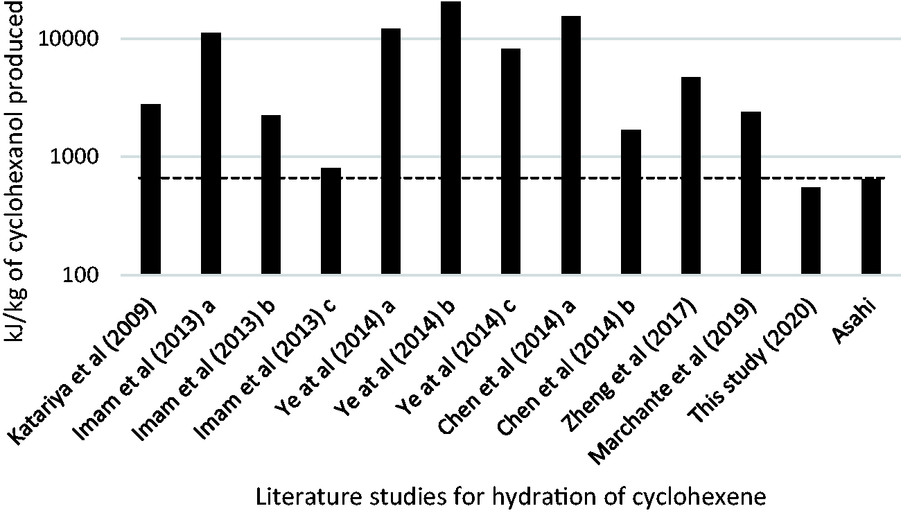
Comparison of different studies from open literature for the hydration of cyclohexene to produce cyclohexanol, using the Asahi process as benchmark.
The simulation of a two-step process
48
deals with the esterification of cyclohexene with formic acid followed by the hydrolysis of the formed ester. The idea and feasibility were proposed previously.
34
This was the first time that a low energy requirement compared with previous reactive distillation process for the production of cyclohexanol is reported. Nevertheless, the process concept is limited by multiple steady states with a narrow operating window and new alternatives were proposed,
47
some of them with very low energy requirements. At the choice
Case
In the reactive distillation column proposed with an excess of water 40 instead of the reactor of the Asahi process, the excess of water allows a total conversion of cyclohexene in the reactive distillation column. A decanter takes advantage of the phase split between water and cyclohexanol to recycle the excess of water. In fact, the case b process is rather similar to the one proposed in the present study, with the difference that the columns above and under the decanter are independent with their own reboilers and condensers. The excess of water is rather low. The ratio of recycled water versus crude feed flow rate is around 0.5 that, according to the Figure 10 of the present study, generates large energy consumption; with a larger excess of water then lower energy consumption would be attained. It was shown 40 that without an excess of water and using a stoichiometric feed to the reactive distillation column, the process has an energy consumption almost 10 times higher than with the two columns and the excess of water (case a). As shown in the present study, the reactive distillation column can be fed stoichiometrically and benefits of the phase split when a side decanter is used. Nevertheless, the study 40 was very inspiring for the process scheme proposal, 41 whose recycle streams are studied and optimised in the present study.
Finally, the use of a third compound, 37 in this case isophorone, although it improves the reactive distillation process, the recovery of the third compound increases the overall energy consumption above the benchmark. A system with 3 columns and 2 decanters is proposed. As indicated in the Introduction section, many other studies propose the use of a third compound but these do not provide an assessment of the energy consumption. The use of a third compound is an interesting point to take into account to improve the proposed processes.
Conclusions
The intensified process of reactive distillation is able to improve the classical process scheme of reactor and separation for direct hydration of cyclohexene to cyclohexanol as already envisaged eighteen years ago. Since then, significant advances have been performed, but without overcoming the performance of the Asahi process proposed 30 years ago, which is still in industrial use. The improvement of the direct hydration of cyclohexene process is desirable for raw material price, selectivity and overall of security compared with the cyclohexane oxidation. A hybrid reactive distillation column with 12 stages with a side decanter is able to reduce the energy requirements of the Asahi process. The recycle flow rate of water from the decanter to the top of the column, and the internal flow rate inside the column of cyclohexene are the main variables of the process. Future work should be focused on the control of this novel process scheme to compete with the simple Asahi process. The results show that very well established industrial processes have the potential to become more efficient based on process intensification combining several operations in a single unit. Although efficient energy production is essential, efficient consumption of the produced energy is also important to reduce greenhouse gas emissions. If the intensified process were applied to the nowadays world production of nylon instead of the classical Asahi process, overall value of CO2 emissions around 67,000 t CO2/y would be avoided. Besides, cyclohexanol has some other uses that would increase this value. It is expected that this study would incentive to apply similar intensified process schemes to other cases.
Future work includes performing rigorous simulations using some of the catalysts proposed in the literature. The kinetic data and catalyst cost allow sizing the units and perform a cost optimisation, studying parameters such as the amount of catalyst and its distribution inside the reactive column stages.
Footnotes
Acknowledgements
Author Alexandra Elena Plesu Popescu is a Serra Húnter fellow.
Declaration of conflicting interests
The author(s) declared no potential conflicts of interest with respect to the research, authorship, and/or publication of this article.
Funding
The author(s) disclosed receipt of the following financial support for the research, authorship and/or publication of this article: The authors would like to thank the financial support of the project CTM2016-76275-R (Ministry of Economy, Industry and Competitiveness –Spanish Government) who provided the opportunity to complete this research.