
Abstract
This article presents an experimental study on the moment-resisting capacity and stiffness of the proposed pre-stressed tube bolted connection. High-strength bolts with tubes were used as fasteners in such connections. A series of monotonic and reversed cyclic loading tests were conducted with T-shaped glulam beam-to-column connections. The strength, stiffness, ductility, and energy dissipation property of the pre-stressed tube bolted connections were obtained and compared with traditional bolted connections. Meanwhile, the effect of self-tapping screw reinforcement on increasing the structural performance of the pre-stressed tube bolted connection was also investigated. The results showed that the initial rotational stiffness of pre-stressed tube bolted connection improved significantly as a result of the friction between steel tubes and steel plate together with the tight-fitting of tubes and timber holes. The ultimate moment-resisting capacity and ductility of the pre-stressed tube bolted connection were also increased when self-tapping screws were applied.
Keywords
Introduction
Timber frame and dowel-type fasteners
Wood is one of the most common renewable construction materials. Nowadays, modern timber frame has attracted more and more attention, since this kind of structural system is able to provide an excellent combination of architectural diversity and affinity of wood.
Connections are key elements for timber frames, as well as any type of structures; connection design has a large impact on the serviceability and resistance of the entire structure. Connection design accounts for up to 70% of the effort in timber structures’ design procedure (Batchelar and Mcintosh, 1988). Dowel-type fasteners with reliable force transmission properties are commonly used for connections in post-and-beam timber structures. According to Johansen’s (1949) yield model, the bearing capacity of dowel-type fasteners is largely determined by the bending capacity of the fasteners and the embedding strength of wood. Timber structures are developing in the direction of high-rise and long-span technologies, which requires better performance of connections. In timber frames as one of the common structural systems in timber buildings, the rotational stiffness of the moment-resisting connections needs to be taken into account as one of the effective design parameters, and the most widely used bolted connections normally have low rotational stiffness and relatively poor ductility. Due to tension perpendicular to grain and longitudinal shear, which are two known weakness of wood, bolted connections are typically designed to transfer shear forces. However, the limited contribution of bolts to moment-bearing capacity is neglected (Lam et al., 2010). Traditional connections with dowel-type fasteners would become very large in order to develop the equivalent strength and stiffness of the members they connect, which cannot be easily achieved in reality (Rodd and Leijten, 2003).
In addition, the vast majority of beam-to-column joints and column-to-base joints in timber frame systems have insufficient rotational stiffness; bolted connections are commonly supposed to be hinged during the design of a timber structure. As a consequence, the overall lateral stiffness of the timber frame turns out to be quite small.
Current improvement methods
One of the most commonly used methods to increase the structural performance of bolted connections is to add reinforcing materials to the surfaces or interfaces of timber members. Based on this concept, Leijten (1991) introduced densified veneer wood (DVW) as a new material to enhance the mechanical properties of the connection. Bouchair et al. (2007) studied the property of plywood as a reinforcing material. The strength and ductility of connections can also be improved by reinforcing the surface of timber members with fiber fabrics, such as textile, glass fiber, and carbon fiber (Haller and Chen, 1999; Haller et al., 1996, 2006; Kasal et al., 2004). Steel materials are also suitable as reinforcing materials. Kevarinmaki (1995) and Blass et al. (2000) investigated thin nail plates or punched metal plates as an alternative to wood-based panels. Since the reinforcing materials offer embedment surfaces and carry the vast majority of embedding loads near failure, the overall strength of bolted connections can be improved significantly. Although small cracks that developed beneath bolts are involved initially, the expansion of splitting due to fasteners bearing at an angle to the grain can be delayed or even prevented by adding reinforcing materials to the surfaces or interfaces of timber members in the entire connection area (Larsen and Jensen, 2000; Rodd and Leijten, 2003).
Blass and Bejtka (2004), Lam et al. (2008, 2010), and Gehloff et al. (2010) investigated the applications of self-tapping screws (STSs) as perpendicular to grain reinforcement. The STSs were fully threaded and arranged perpendicular to the grain and to the bolt axis. The ductility and the strength of the connection were enhanced, because the tensile stresses perpendicular to grain were transferred, effectively avoiding splitting failure. Compared with adding reinforcement materials on the surface of timber members, STSs can be applied to new construction projects and existing structures with simple processing procedures that will not affect the appearance of wood members.
Apart from the two aforementioned methods, Guan and Rodd (2001a, 2001b) and Leijten et al. (2006) used hollow steel tubes instead of solid dowels as an enhancing method of ductility. By expanding the diameter of hollow steel tubes or injecting resin to fill the void between timber holes and tubes after the tubes are installed, hollow steel tubes have also turned out to be effective on increasing the stiffness of the connection with careful control during the construction process.
Moreover, some researchers used more than one method to enhance the performance of bolted connections, such as adopting DVW and hollow steel tubes at the same time (Guan and Rodd, 2001a, 2001b; Leijten et al., 2006; Rodd and Leijten, 2003). Additionally, Idota (2005) and Idota and Mineoka (2006) used the serrated surface of timber members without any new material added.
Although the embedding stiffness can be increased partly by adding reinforcing materials, the effectiveness of most of the aforementioned methods regarding increasing the stiffness of bolted connections, especially initial stiffness, is quite limited. This is primarily due to the fact that it does not overcome the problems of hole clearance and direct load take-up for bolted connections (Rodd and Leijten, 2003).
Pre-stressed tube bolted connection
To improve stiffness, especially the initial stiffness of bolted connections in timber constructions, this article introduces the semi-rigid pre-stressed tube bolted connection (PTBC), as shown in Figure 1. This connection consists of timber members, steel plate, tubes, high-strength bolts, washers, and nuts. The tube has two layers that are bonded together, its inner layer made of steel and its outer layer made of polyvinyl chloride (PVC). First, wood members and steel plate are assembled. Second, tubes designed to fit tightly in the timber holes are then embedded into the holes on wood members from two sides. Third, bolts are inserted into the tubes. Fourth, both ends of the bolts must then be anchored with washers and nuts; the outer diameter of washers should be larger than the outer diameter of the tubes. Finally, the high-strength bolts are pre-stressed and the pretension is transferred to steel tubes through nuts and washers. Therefore, friction force will be established between the steel tubes and the steel plate.

Configuration of the pre-stressed tube bolted connection.
The tight fit between the tubes and timber holes leads to a direct load take-up. Due to the friction between the steel tubes and the steel plate, the PTBC can resist the relative slip between the steel tubes and the steel plate or bolts in the initial loading stage. The initial stage can be taken as the friction stage. During this stage, the timber beneath the tubes is in elastic range. Therefore, its main advantage is to overcome the adverse effects of hole clearance and inaccurate fabrication in order to ensure enhanced initial stiffness. When friction force is overcome, relative sliding between components will occur. Like the initial loading stage of ordinary bolted connection (OBC) that is meant to overcome the gap between bolts and bolt holes, this stage of PTBC is defined as the slip stage. Until the bolts come in contact one by one with the inner wall of steel tubes and bolt holes on steel plate, the PTBC will work like the OBC, which can be accepted as the normal stage.
Although the inner diameter of the steel tube is larger than the diameter of the bolt, the gap between them has no effect on the friction stage; conversely, the deformation ability of the slip stage is affected by the size of the gap. At the same time, the installation is convenient due to the gaps between the tubes and the bolts. Because the outside diameter of the steel tube is much larger than the diameter of the bolt, the embedding stress (calculated by equation (1)) of PTBC will be less than that of OBC. As a result, the embedding stiffness of PTBC is also increased to some extent in the friction stage and the normal stage
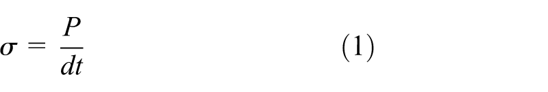
where
As shown in Figure 2, the steel plate is sandwiched by steel tubes on two sides, which are sandwiched by washers. The compression due to bolt pretension is fully supported by the interaction force between the steel tubes and steel plate. Since the modulus of steel is much larger than that of wood, the shrinkage of timber members has no influence on the pretension, and the deformation of steel tube is negligible with proper wall thickness under pre-stressing force. Thus, even during long-term use, the reduction in bolt pretension is theoretically insignificant.
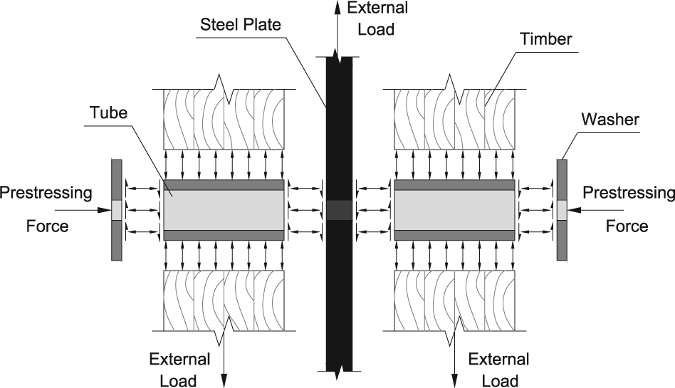
Load-bearing mechanism at the initial loading stage of the pre-stressed tube bolted connection.
The structural design of OBC is complicated when considering nonlinearity. The variation in joint stiffness is large due to the differences in construction quality. That is the reason why the real behavior of OBC is not taken into account (Larsen and Jensen, 2000). In contrast, PTBC demonstrates a slight initial slip with elastic behavior, which allows it to overcome the disadvantages of the OBC. It is feasible to take the real behavior of PTBC into account during the design procedure.
Specimens and test methods
To evaluate improvements regarding stiffness and the moment-resisting capacity of PTBC with or without STS reinforcement, a series of experimental tests were conducted with commonly used moment transmitting T-shaped beam-to-column connections. The experiments consisted of monotonic tests (series “M”) and reversed cyclic tests (series “C”). The test results of OBCs (series “O”) were used as baseline data, PTBCs were considered to be reinforced connections (series “R”), and PTBCs reinforced with STSs were set as series “SR.” The observed differences of failure modes have been evaluated, and the strength, rotational stiffness, ductility, and energy dissipation capacity of the connections have been compared.
Specimens
No. 2 spruce–pine–fir (SPF 2#) glulam was used to fabricate wood specimens. The cross section and length of the column were 384 mm × 240 mm and 1400 mm, respectively; the cross section and length of the beam were 384 mm × 150 mm and 1000 mm, respectively (as shown in Figure 3). The moisture content (MC) of each timber specimen was measured prior to testing and the results indicated an average MC of 15.46%. The average air-dry density of timber members was 438.67 kg/m3.

Construction detail of the connection for all series.
The lengths of bolts applied to the column and beam members were 300 and 220 mm with an unthreaded length of 200 and 120 mm in the middle, respectively. All bolts were grade 8.8 high-strength steel bolts with a diameter of 16 mm, and the bolts used for series R and series SR were pretensioned with 80 kN in accordance with the steel structure code of China (GB 50017, 2003). The pretension load was applied to high-strength bolts by a click-type torque wrench, and the torque wrench was calibrated with sufficient accuracy (error less than 0.5%). Bolt holes on timber members were drilled with diameters of 20 mm for series O and 32 mm for series R and series SR: this dimension was the only difference in the parameters of timber specimens. The ASSY PLUS VG STSs with full threads (as shown in Figure 4) were used for series SR. The diameter and length of the STS were 8 and 380 mm, respectively. STSs were arranged both perpendicular to the grain and to the bolt axis in order to reinforce the timber specimens before assembly. The drilling positions and arrangement of STSs are shown in Figure 5.
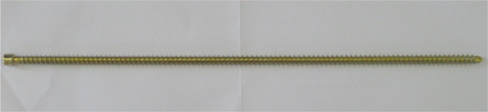
Self-tapping screw used for series SR.
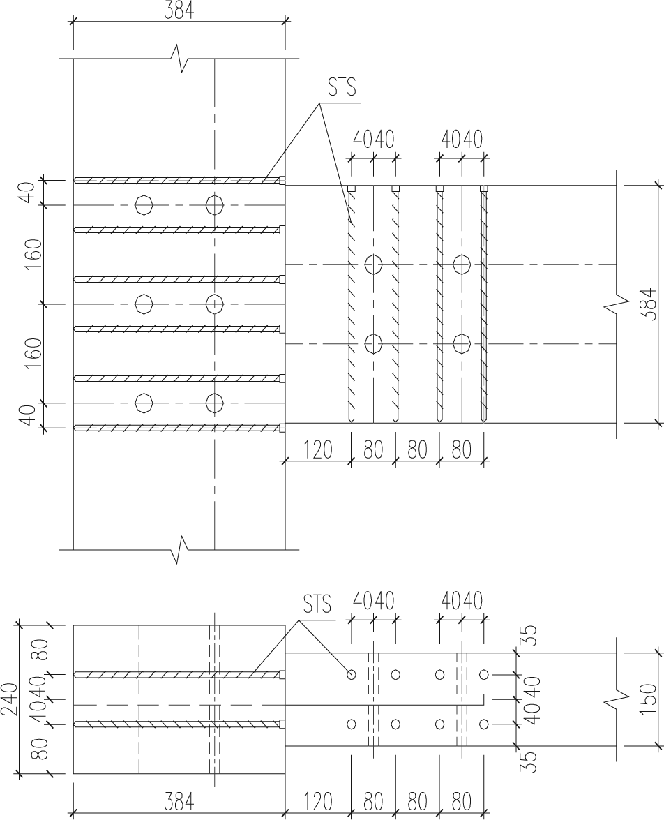
Arrangement of STSs of series SR.
The steel plate was grade Q235B with the yield strength of 235 MPa (GB 50017, 2003) and 16 mm thick with a bolt hole diameter of 17 mm. No special treatment was applied to the surface of the steel plate, so the average friction coefficient between the steel plate and the end surfaces of the steel tube was 0.30 in accordance with the steel structure code of China (GB 50017, 2003). Additionally, a slot was cut to 18 mm width on the timber members for easy installation of the steel plate. The outer diameter and wall thickness of the PVC pipes were 32 and 1.5 mm. The grade, outer diameter, and wall thickness of the steel tubes were Q345B with the yield strength of 345 MPa (GB 50017, 2003), 28 mm, and 4 mm, respectively. The length of the steel tubes installed on column and beam was 111 and 66 mm, respectively. The thickness and outer diameter of the washer were 3 and 50 mm.
Test methods
All tests were conducted using an electro-hydraulic servo pseudo-static loading system, which had a maximum travel distance of 250 mm in either direction. The general test setup is shown in Figure 6. In order to facilitate loading, the column was fixed to the testing platform, and horizontal force (F), which was automatically recorded by the actuator, was applied to the top of the beam through a hydraulic jack. Six series (OM, OC, RM, RC, SRM, and SRC), each with two replications, were tested. A total of 12 connection tests were completed under monotonic and reversed cyclic loading. With reference to test standards ASTM D1761 (2000) and ASTM E2126 (2009), the displacement-controlled loading protocol was used for both monotonic and reversed cyclic loading tests. The monotonic tests involved pre-loading to 10% of the estimated ultimate load and formal loading that pushed the specimen to failure (specimens were obviously damaged or loading force fell to 80% of the ultimate bearing capacity). The actuator displacement was controlled at a constant rate of 5 mm/min.
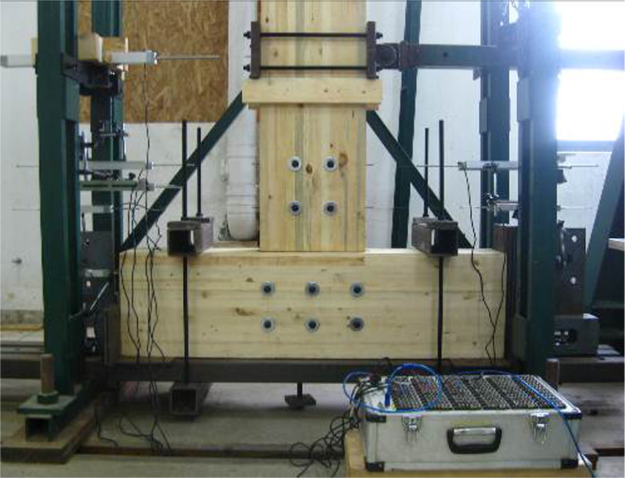
Test setup.
The Consortium of Universities for Research in Earthquake Engineering (CUREE) protocol is intended to model ordinary ground motion typical of most far-field locations (Gatto and Uang, 2003). Because the equal amplitude cycles of the International Organization for Standardization (ISO) protocol may be too demanding and cause a conservative estimate of strength and deformation capacity, the CUREE protocol was chosen for reversed cyclic tests. This loading protocol consists of initiation cycles, primary cycles, and trailing cycles. Considering the reference deformation Δ to be 60% of the monotonic displacement capacity Δfailure, the loading history starts with six initiation cycles at an amplitude of 0.05Δ, followed by the first primary cycle of 0.075Δ, up to a primary cycle with an amplitude of 2.0Δ. Each primary cycle is then followed by a series of subsequent trailing cycles with an amplitude of 75% of the primary one. The CUREE protocol is shown in Figure 7.
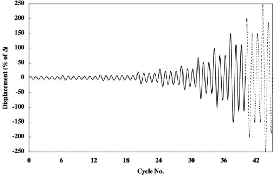
CUREE protocol for reversed cyclic loading test.
Three linear voltage displacement transducers (LVDTs) installed horizontally were used to measure the lateral displacement at different locations of the beam (as shown in Figure 8). Among them, LVDT1 was placed at the height of the load application, while LVDT2 and LVDT3 were located at the center of the bolts and on two sides of the steel plate. The same was done for the steel plate with LVDT4–LVDT7 placed at the bolt location to record the relative rotation of the steel plate. In addition, the overall displacement of the connection was monitored by LVDT8 at the end cross section of the column to ensure no loosening took place. The accuracy of LVDT1, LVDT2–LVDT7, and LVDT8 was 0.1, 0.05, and 0.0125 mm, respectively. The data recording frequency was 0.2 Hz. Assume that the rotation center was located in the centroid of the bolt group on the column, thus the moment (M) and relative rotation angle (θ) of the beam to the column could be calculated by equations (2) and (3), respectively. These values led to the moment–rotation curves
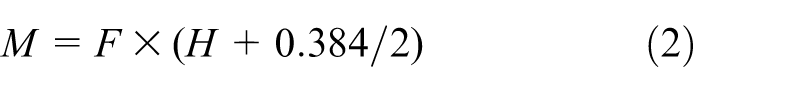

where S1, S2, and S3 are the lateral displacements measured by LVDT1, LVDT2, and LVDT3, respectively.
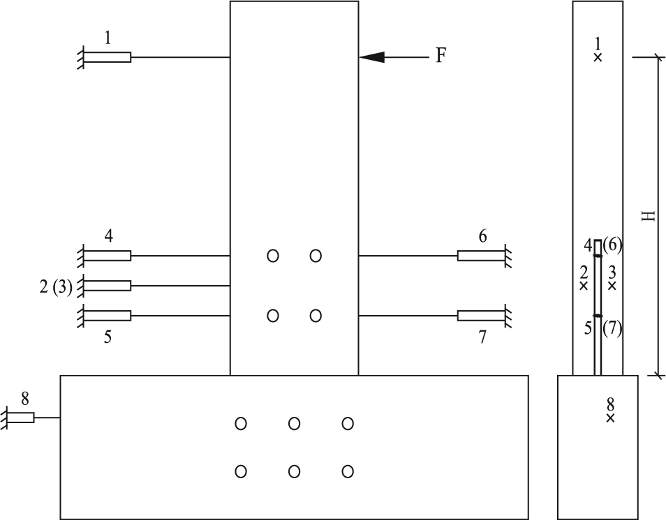
Transducer position layout.
Results and discussions
Failure modes
As shown in Figure 9, due to the splitting failure of the wood together with the embedding failure of wood members and bolts’ failure, the failure mode of series OM can be taken as post-yield brittle failure. As shown in Figure 9(a), the splitting of series OM is through two bolts in a line and parallel to grain in the connection area, and some row shear failure occurred. Due to the stress concentration, cracks generally occurred around the bolt hole on the beam and extended first toward beam bottom and continued upward along the wood grain. The row shear failure between two bolts or between the last bolt and beam bottom was caused by tension perpendicular to grain combined with longitudinal shear stresses. The splitting failure of the beam led to the connection reaching the maximum bearing capacity followed by a rapid drop of resistance. For series OM, the washers squeezed into the wood (as shown in Figure 9(b)).
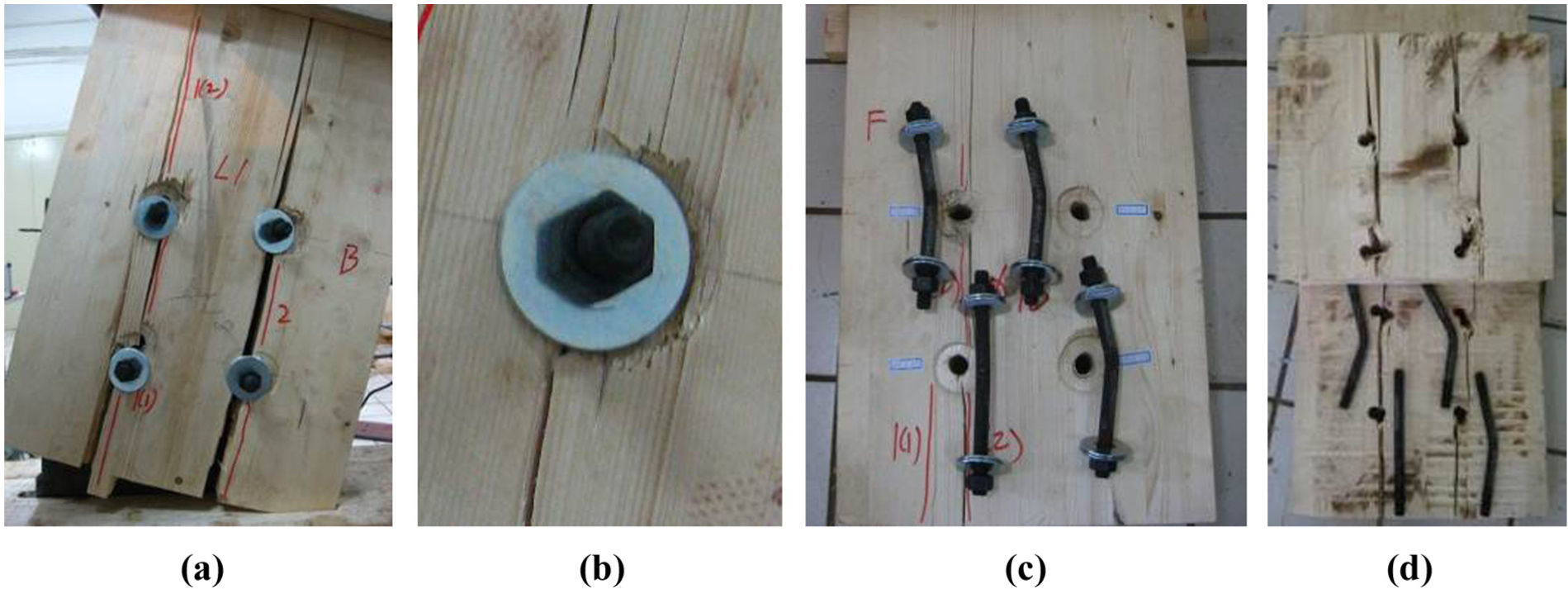
Failure mode of series OM: (a) splitting failure of wood, (b) washer squeezed into wood, (c) "one hinge" yield model of bolts, and (d) embedding failure of wood.
As shown in Figure 9(c) and (d), the bolts for series OM show “one hinge” yield model failure with one plastic hinge midway where they bore on the steel plate, while the other part of the bolt is still straight. Due to the rotation of the bolts, the internal and external surfaces of the wood members were squeezed to damage with embedment failure. It should be noted that the bending deformation of the bolts on the compression and tension sides of the beam was different. The bending deformation of the bolts on the tension side was larger and the embedding damage of the bolt hole was more serious; part of the force on the compression side was transmitted through embedding between the beam and the column in large rotation.
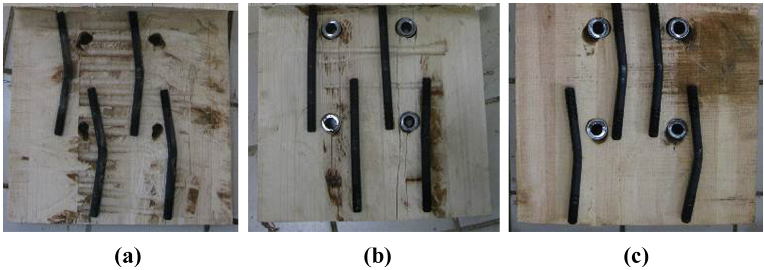
As shown in Figure 10(a), the primarily detectable damage of series RM was splitting and row shear failure between two bolts along the direction of wood grain. Steel tubes resisted the washers in series RM, and as a result they just slipped along in the same direction as the force (as shown in Figure 10(b)). Only limited wood crushing of timber holes and no apparent bolt bending took place in the connection after disassembly (as shown in Figure 10(c) and (d)). Bolts and steel tubes were generally in the elastic range. Due to the transverse compression of wooden fibers around steel tubes, there were obvious tensile stresses perpendicular to grain. When the transverse tensile stresses exceeded the tensile strength perpendicular to wood grain, the embedding strength of wood and bending strength of bolt did not fully develop. Consequently, the PTBC without STS reinforcement was prone to brittle splitting failure with a rapid decrease in moment-carrying capacity under rotational actions.
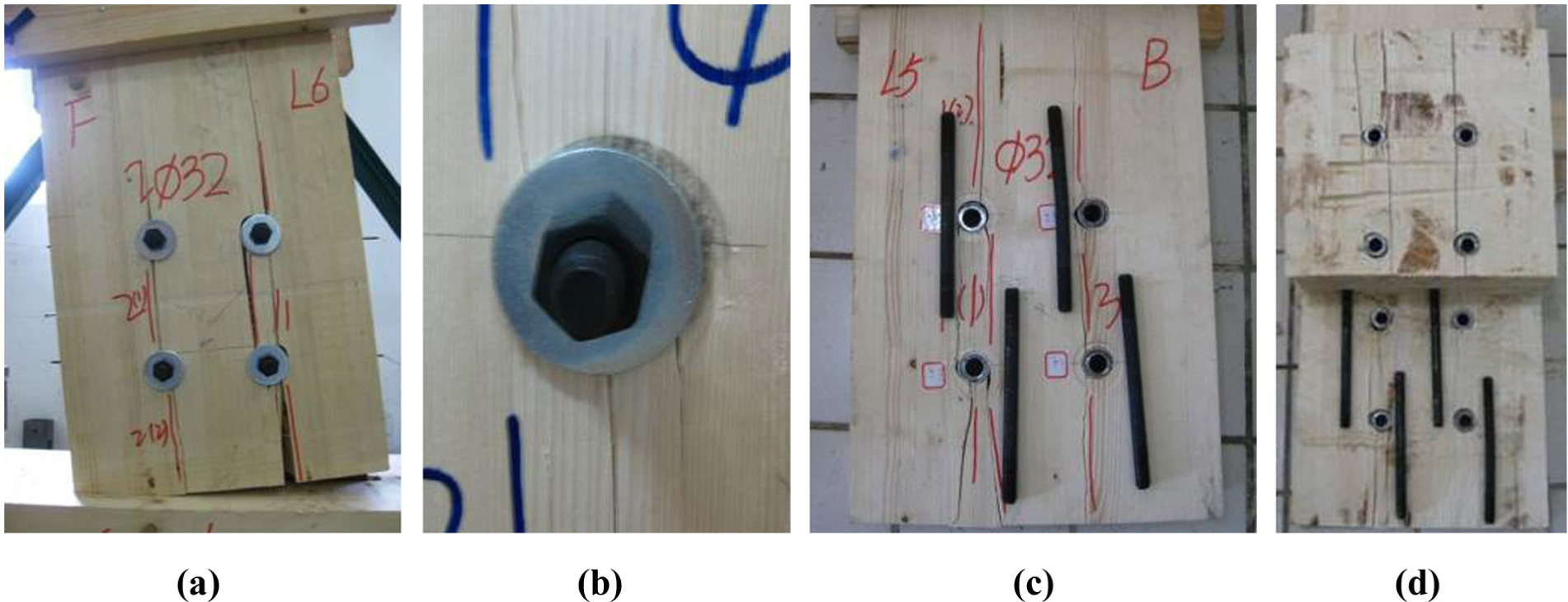
Failure mode of series RM: (a) splitting failure of wood, (b) slipping of washer, (c) no apparent bending of bolts, and (d) limited wood crushing of timber holes.
When PTBCs were reinforced with STSs, the failure mode of series SRM was much more ductile. Although the finial rotation of series SRM was larger than that of series OM and series RM, the width and length of the wood cracks in series SRM were significantly reduced. As shown in Figure 11(a), failure occurred primarily along the tension side of the beam. Failure modes consisted of splits between two bolts and row shear from the bottom bolt to the beam bottom, respectively. The failure mode occurred largely in the form of wood being crushed around the tubes on the compression side (as shown in Figure 11(b)). The “one hinge” yield model of bolts and embedding deformation of the wood took place as shown in Figure 11(c) and (d). It can also be seen in Figure 12 that the plastic deformation of tubes occurs at the end surface in contact with the steel plate. Since the expansion of cracks on timber beams was effectively limited by STSs, the components’ (i.e. wood members, bolts, and steel tubes) strength of the connections of series SRM was fully utilized when compared with series RM.
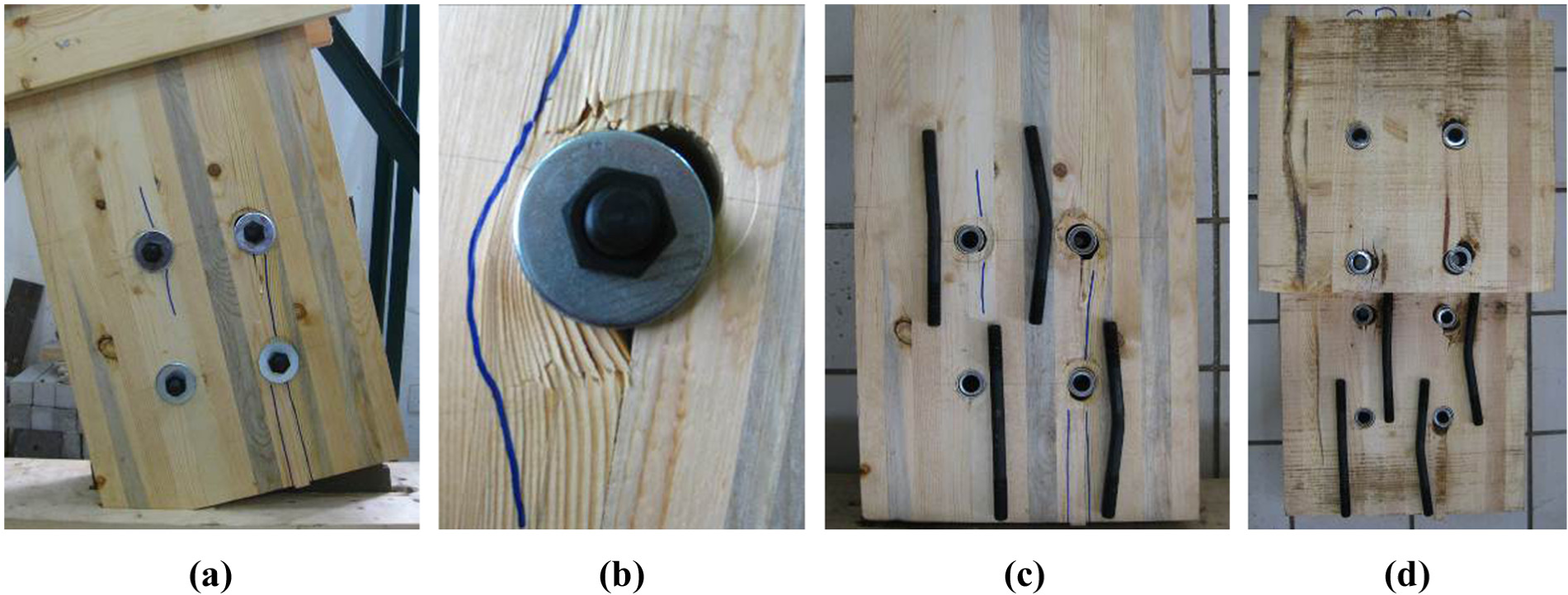
Failure mode of series SRM: (a) failure mode of wood, (b) wood crushing around tubes, (c) "one hinge" yield model of bolts, and (d) embedding deformation of wood.
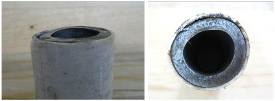
Deformation of the tubes of series SRM.
In addition, there were evident impressions on the steel plate in series RM and series SRM due to the pressure of the steel tubes. With careful observation, it was not difficult to find the slippage trace on the steel plate caused by the slip between the steel plate and steel tubes (as shown in Figure 13). As shown in Figure 14, there is no obvious deformation of STSs in series SRM. Only the STS located at the bottom of the beam showed slight bending, which indicated the strength of the STS remained to be fully utilized.

Slippage trace on steel plate.

Deformation of STSs of series SRM.
All wood beams showed rigid rotation, and no residual bending deformation was observed in wood members after the load was removed. Thus, the wood members away from the connection area were thought to be in the elastic range. After visual examination, very little hole bearing deformation was found on the steel plates. The failure modes of series C were similar to the monotonic tests, but the damage level of series C was worse than the monotonic tests. Due to reversed cyclic loading, the bending deformation of bolts and the embedding damage of the wood are similar on both sides of the beam (as shown in Figure 15).
Failure modes under reversed cyclic loading: (a) series OC, (b) series RC, and (c) series SRC.
Moment–rotation curves under monotonic tests
The moment–rotation curves obtained from the monotonic test data are shown in Figure 16. The deviation of each group is within 10%; for ease of comparison, the average moment–rotation curves of each series are given in Figure 17.

Moment–rotation curves under monotonic test: (a) series OM, (b) series RM, and (c) series SRM.

Average moment–rotation curves of series M.
For the OBC, it is only when the bolts and bolt holes are in contact with each other sufficiently after the initial slip that the connection can perform effectively under external load. Due to the unpredictable initial slip response, the M–θ curves of series OM are not smooth at a low load level, as shown in Figure 16(a). And the wood members beneath the bolts showed plastic deformation under embedding pressure at low load level. Due to the nonlinearity of the M–θ curves of series OM, it is difficult to distinguish between the elastic stage and the plastic stage distinctly.
For the series RM and SRM, as shown in Figure 16(b) and (c), the PTBCs are at the friction stage when the rotation is between 0° and 1.5°. Because of immediate force transmission, the M–θ curves are smooth with a linear growth trend. The connection behaved elastic at this stage. For PTBCs in this test, the ideal gap between the bolts and steel tubes was 2 mm, and the slip stage corresponded to the rotational deformation from 1.5° to 2°. Due to the dislocation between the steel tubes and steel plate, there were slight fluctuations on the M–θ curve of RM-1 (as shown in Figure 16(b)); the joint stiffness decreased significantly in the slip stage. When the gap was overcome completely with the deformation exceeding 2°, the normal stage began with a small increase in joint stiffness; the stiffness of PTBC decreased gradually afterward. It should be noted that there might be initial contact between the bolts and the inner wall of the steel tubes after assembly, which was similar to OBC. As such, the slip stage and the stage division of RM-2 and SRM-2 were not as obvious as RM-1 and SRM-1. However, that initial contact had no effect on the initial stiffness during the friction stage.
By comparing the average curves in Figure 17, the stiffness of series RM and series SRM is almost the same before the slip stage. Because timber beneath the tubes performed elastically, the STSs had yet to take effect. However, after the slip stage, the STSs gradually enhanced the embedment strength and stiffness with the yielding of timber around the tubes; therefore, the stiffness of series SRM was larger than that of series RM. Additionally, the connection strength of series SRM came into full play and the ductility of PTBCs was greatly improved without any significant decline in load-carrying capacity.
Parameter definition
Some key parameters are defined from M–θ curves to analyze the test result. The maximum bearing capacity of series OM and series RM is the peak moment in the M–θ curve, named as Mp; its corresponding angle is denoted as θp. When complete wood splitting takes place, the angle is defined as failure angle, named as θf, and the corresponding moment is denoted as Mf. Since there is no obvious damage of series SRM, for ease of comparison, the same value of θp of series OM has been used for series SRM, and the corresponding moment is Mp.
The yield point is defined as the point on the M–θ curve when the plastic performance of the connection begins to take place. For OBC, it is difficult to define the yield point with any measure of exactness because of the high nonlinearity of the load–displacement curve. The method proposed by Yasumura and Kawai (1998) was chosen to determine the yield point of series OM; the corresponding moment and angle have been denoted as My and θy. Calculations of related parameters are provided in equations (4) and (5). The combination of independent slopes of the initial and “immediate post-elastic” stiffness proposed by Yasumura and Kawai (Y&K) method (see Figure 18) produced reasonable estimate of the yield point regardless of curve shape (Muñoz et al., 2008)

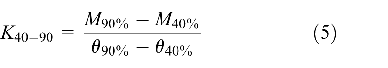
where M10%, M40%, and M90% are the moments in M–θ curve equal to 10%, 40%, and 90% of Mp, respectively; θ10%, θ40%, and θ90% are the rotation angles in the M–θ curve corresponding to M10%, M40%, and M90%, respectively.
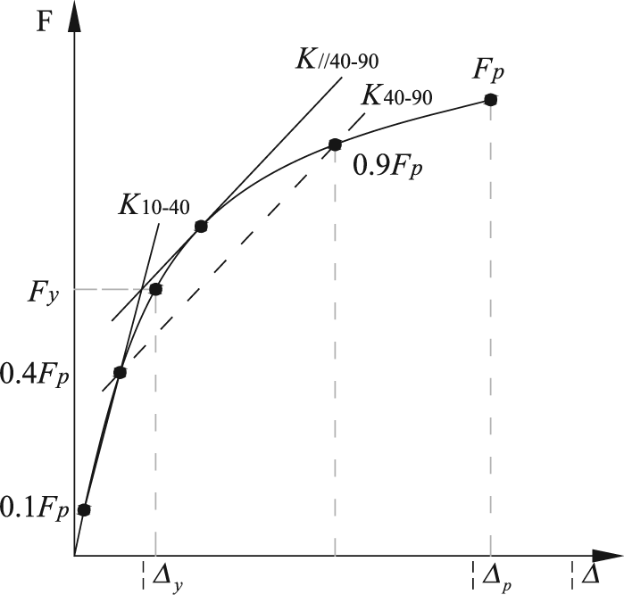
Y&K method for the estimation of yield point.
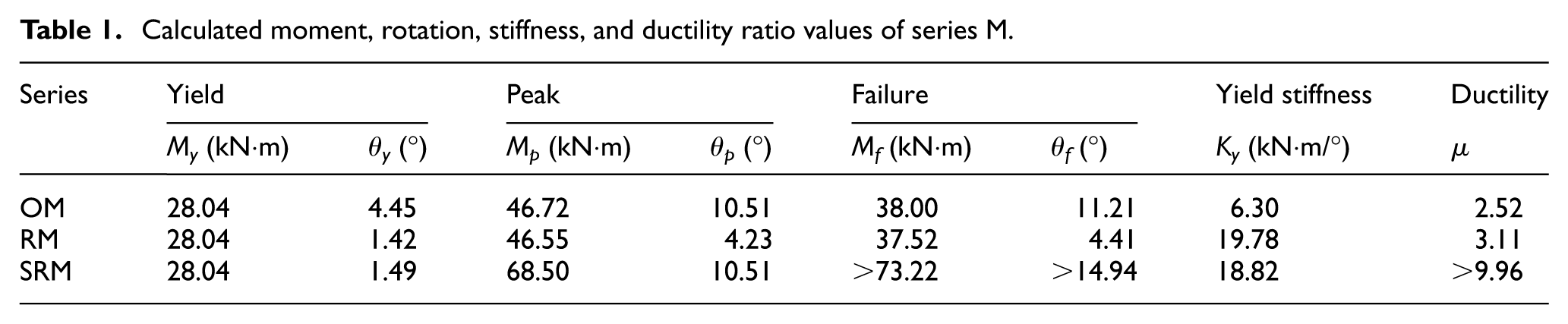
For series RM and series SRM, because different stages exist during the loading process, and because M–θ curves have an obvious elastic stage, the Y&K method is not appropriate. The moment-bearing capacity and the angle at the end of the friction stage have been defined as Ms and θs, respectively. According to the analysis in section “Moment–rotation curves under monotonic tests,” the θs of series RM and series SRM is 1.5° approximately; Ms happens to correspond with the calculated My of series OM, which is 28.04 kN·m as given in Table 1. Therefore, Ms is taken as My for series RM and series SRM. Since Ms could not be accurately determined from the M–θ curves, for the purpose of comparison, the equal My of series OM has been applied for series RM and series SRM. θy corresponding to 28.04 kN°m of series RM as well as series SRM are 1.42° and 1.49° (as given in Table 1), which are close to and smaller than 1.5°, so this approach method is suitable.
Calculated moment, rotation, stiffness, and ductility ratio values of series M.
Prior to the yield point, series RM and series SRM show apparent elasticity, and series OM is also regarded within the elastic range. Thus, yield stiffness (which differed a little from K10-40 calculated by equation (4)) is defined by equation (6) to compare the initial stiffness of each group. The ductility ratio is defined by equation (7)

Results and discussions of monotonic tests
The results of series OM are set as basic data to compare and evaluate the performance of PTBCs. Table 1 summarizes the calculated results of series M, derived from the M–θ relationships, as previously described. All the data in Table 1 are the average values of two replications for each series, which differ by not more than 10%, in line with the requirements (ASTM D1761, 2000; ASTM E2126, 2009).
Moment-bearing capacity
It can be seen from Figure 19 that when compared with series OM, Mp of series RM showed no significant change, while Mp of series SRM increased by 46.62%. Because of premature cracks in the tension perpendicular to grain or shear parallel to grain, neither the bearing nor the deformation capacity of series RM was fully developed. The ultimate strength of PTBC was determined by the risk of splitting. When wood cracking was restricted by STSs or other methods, the ultimate strength of PTBC could be increased substantially when the diameter of the steel tubes was larger than the diameter of the bolts.
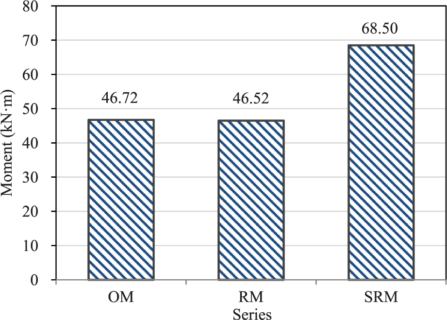
Comparison of peak moment (Mp).
Rotational stiffness
The rotational stiffness of the PTBC showed significant improvement. As shown in Figure 20, when compared with series OM, Ky of series RM and series SRM increased by 206% on average. If taking the average θy (equal to 1.45°) of series RM and series SRM as the control target, the corresponding moment capacity of series OM is 7.9 kN°m, which is only 28% of the moment of PTBCs (equal to 28.04 kN°m, as given in Table 1).

Comparison of yield stiffness (Ky).
The initial stiffness of series OM was very low because it had to overcome the clearance between the bolts and the bolt holes. Because the bolts act locally in timber, the nonlinear behavior of the timber around the bolts controlled the stiffness of series OM. In addition, due to the bending deformation of the bolts, the embedment was uneven between the bolts and bolt holes on the timber members along the bolt length, which further reduced the stiffness of the OBC.
The PTBCs can ensure direct load take-up with tightly fitting tubes and timber holes; the PTBCs also prohibit slip using the friction force between the steel plate and steel tubes in the friction stage. The bearing stress of the timber in the PTBC was even along the tube length and distributed with the larger embedding area; therefore, the joint stiffness was also enhanced to some extent. The PTBCs performed as a semi-rigid moment-resisting timber connection, while the OBCs acted more like a hinge.
When deformation governs the structure design at the serviceability limit state, the requirements can then be met by enhancing the friction stage of the PTBC. This problem can be solved using higher grade bolts with higher pretension or surface treatment applied on the steel members in order to increase the friction coefficient between steel tubes and steel plate; both methods can improve the frictional force between the steel tubes and steel plate at the friction stage. The moment-bearing capacity at the friction stage of PTBC will also be improved accordingly.
Ductility
The requirements for ductility are more difficult to satisfy than those for strength, since ductility depends on a wide range of issues. Determination of the yield point is crucial for the estimation of ductility behavior.
Due to the splitting of wood beams, failure modes of series OM and series RM were somewhat brittle with moment-bearing capacity decreasing rapidly, thus it does not make much sense to define the ductility ratio using equation (6) for these two series. However, given the contrast of µ, it can be taken as good proof of demonstrating the ductility enhancement with STSs. The ratio µ of series OM and series RM is 2.52 and 3.11, respectively. According to the ductility classification for the connections proposed by Smith et al. (2006), the ductility levels of series OM and series RM are both in the class of low ductility (2<µ ≤ 4). The ratio µ of series SRM is greater than 9.96, which is, respectively, more than 3.9 and 3.2 times than that of series OM and series RM. The ductility of series SRM belongs to the highest level: high ductility (µ > 6).
It should be noted that ductility in general describes the ability of a structure to undergo deformation beyond the elastic range before its collapse (Blaß and Schädle, 2011). According to this concept, the linear friction stage can be taken as the elastic stage, while the rotation in the slip stage and the normal stage is considered to be plastic deformation. In practice, if the applied load is controlled within the friction stage at serviceability limit state, the bearing capacity and deformation that follows are regarded as safety reserve. From this point of view, the relative ductility of PTBC without STSs reinforcement seems to be reasonable and would be not as poor as the absolute deformation capacity of PTBC.
Results and discussions of reversed cyclic tests
The typical hysteresis loops and average skeleton curves of series C are shown in Figures 21 and 22, respectively. As is evident, the bearing capacity of series OC and series RC declines at the amplitude of 2.0Δ with a splitting failure, while the bearing capacity of series SRC maintains with no decrease at a large deformation. When the PTBC is reinforced with STSs, the seismic performance will be effectively improved under large earthquake.
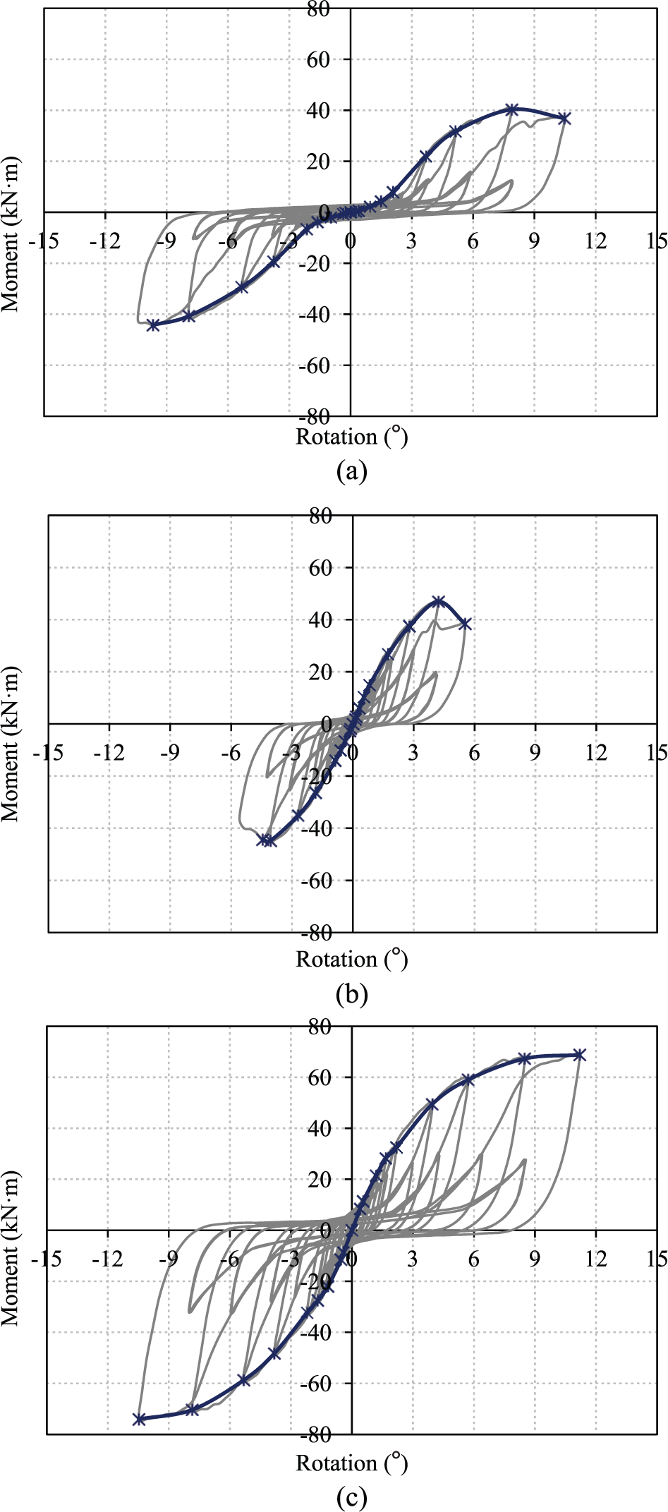
Typical hysteresis loops of series C: (a) series OC, (b) series RC, and (c) series SRC.
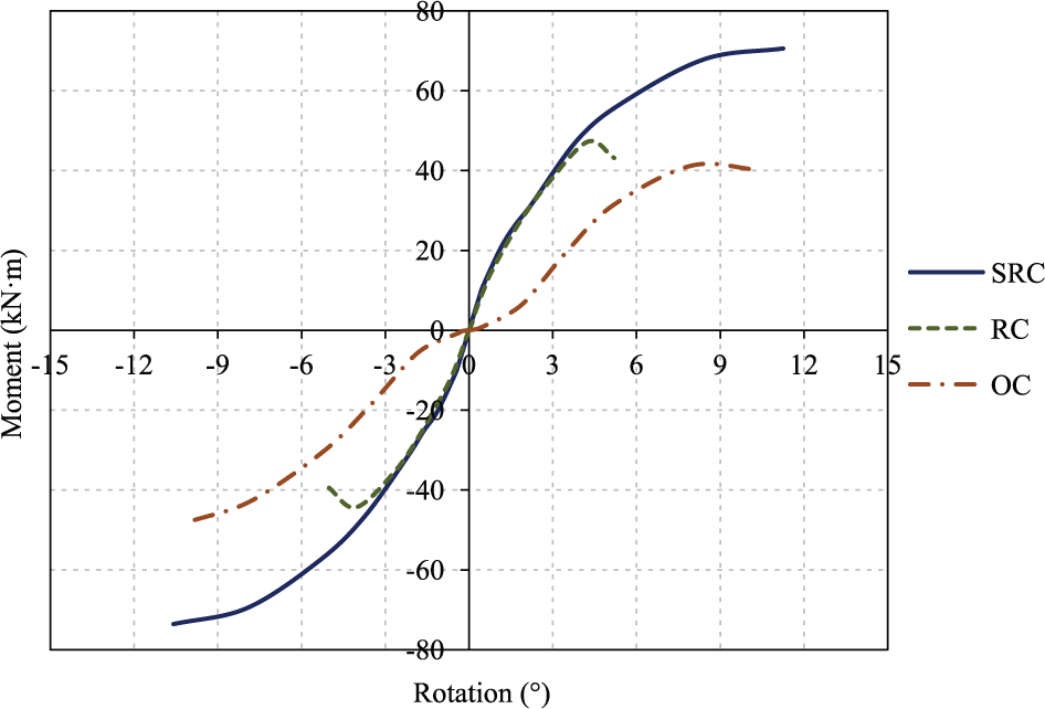
Average skeleton curves of series C.
As shown in Figure 21, pinching of the hysteresis loops was observed for series OC during the entire process as common for most bolted connections. While the hysteresis loops of series SRC were plump before the primary cycle of 0.4Δ. After that, pinching of the hysteresis loops of series RC and series SRC began to take place, and with increasing of the primary cycle, the pinch phenomenon of these two series became increasingly apparent. By comparing the skeleton curves in Figure 22, series OC showed more of an obvious initial slip than the PTBC series and series OM. The reasons for this are that the impact of the hole clearance for the OBCs is magnified under reversed cyclic loading; the impact of the initial slip is eliminated partly by pre-loading under a monotonic test.
Secant stiffness (Ki), defined by equation (8), was available to represent the stiffness degradation, which reflects the damage accumulation of the connection. To compare the energy dissipation capacity, the so-called equivalent viscous damping ratio (EVDR) value (εeq) (BS-EN 12512, 2001) was used (as shown in Figure 23 and equation (9)). It is a non-dimensional parameter that expresses the hysteresis damping properties of the connection
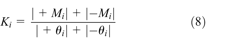
where +Mi and −Mi are the positive and negative peak moments in primary cycles, respectively; +θi and −θi are the rotation angles in the same loop corresponding to +Mi and −Mi, respectively
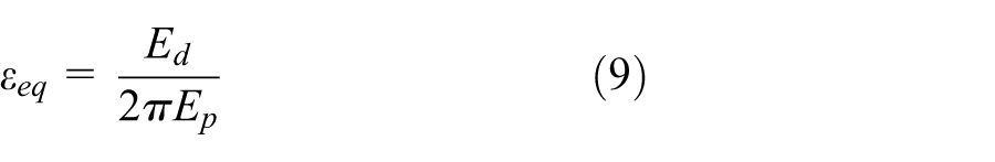
where Ed is the energy dissipated in a one-half cycle, and Ep is the available potential energy.
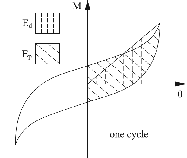
Determination of the EVDR value of one cycle.
The potential influence of installation and loading device is eliminated at initial loading process; Ki and εeq of each primary circle from 0.2Δ to 2.0Δ under reversed cyclic loading are given in Table 2. All the data are the average values of two replications for each series.
Calculated secant stiffness Ki and EVDR value εeq.
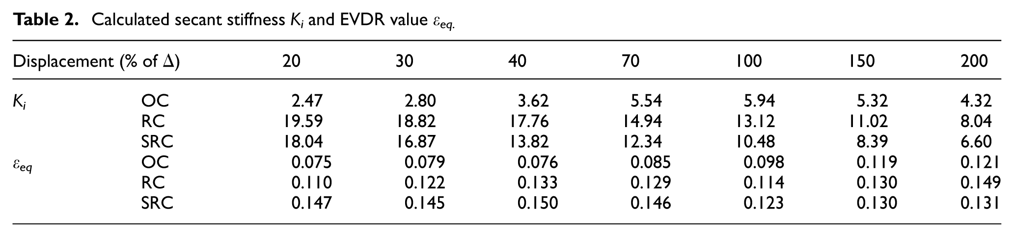
As shown in Table 2, Ki and εeq of series OC are much lower than those of series RC and series SRC, especially at a low load level. Because the pinching phenomenon and the low stiffness of OBC were largely attributed to hole clearance, the enlargement of the bolt holes on the timber members and the plastic bending deformation of the bolts meant a further reduction in energy dissipation capacity, while the gap between the tubes and the bolts made main contribution to the pinching phenomenon and stiffness degradation of the PTBC. In addition, cracks also contributed to the stiffness degradation for each series at high load levels.
According to the monotonic tests, Δ of series RC was 50 mm, and Δ of series SRC was set as 90 mm, which was equal to that of series OC. In order to compare and better understand the mechanism of OBC and PTBC, the changing trend curves of Ki and εeq for series OC and series SRC are illustrated in Figures 24 and 25, respectively.
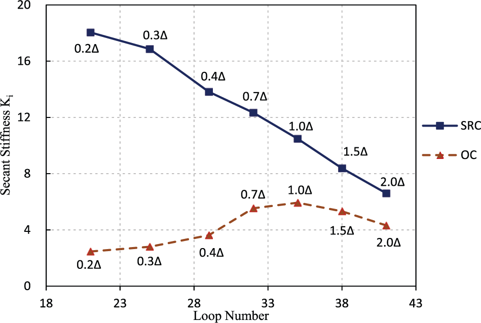
Increasing trend of secant stiffness Ki.
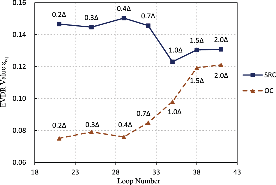
Increasing trend of EVDR values εeq.
For series OC: (1) only by gradually overcoming the hole clearance are the bolts able to come in full contact with the timber holes, so Ki and εeq are at low level from 0.2Δ to 0.4Δ; (2) both bolts and timber were almost within the elastic range when they came in contact with each other at the beginning, so Ki increased quickly while the increasing trend of εeq was moderate from 0.4Δ to 0.7Δ; (3) with the yielding of bolts and timber under embedding pressure and with the formation of some slight cracks, the connection began the main stage for energy dissipation, so stiffness degradation began to take place, while εeq increased rapidly from 0.7Δ to 1.5Δ; and (4) with the appearance and propagation of conspicuous cracks, stiffness degradation was significant and the increasing trend of εeq slowed down from 1.5Δ to 2.0Δ.
With consideration to the Ki curve of series SRC in Figure 24 in conjunction with the value of Ki of series RC from 0.2Δ to 0.4Δ in Table 2, it can be determined that before the friction was overcome (corresponding to 0.3Δ of series SRC), the secant stiffness of the PTBC showed slow degradation due to some minor gaps (which may have been caused by fabrication errors) or slight plastic deformation (which may have been formed by PVC pipes or timber around tubes). When the external force is larger than the friction force (corresponding to 0.3Δ to 0.4Δ of series SRC), Ki of PTBC decreases markedly due to a relative slip between the steel tubes and the bolts. Afterward, Ki of PTBC maintains the linear degradation, because the gaps between the steel tubes and the bolts need to be overcome repeatedly and plastic deformation of the components constantly emerges.
As shown in Figure 25, prior to 0.7Δ, the εeq of series SRC maintains a high level, which indicates the PTBC has a strong energy absorption capacity at low and moderate load levels. The pre-stress loss is minimal before the deformation of bolts and steel tubes takes place. Therefore, external force must overcome the friction force continuously during the loading process, which plays a major role in energy dissipation. After 0.7Δ of series SRC, most of the pre-stress force was lost with significant bending of bolts. As a result, the friction between the steel tubes and the steel plate and the energy dissipation capacity of the PTBC decrease significantly. Then with the occurrence of plastic deformation and mild cracks, εeq of the PTBC stabilizes at a moderate level.
Conclusion
This study investigated the moment-resisting performance of the proposed PTBC through monotonic and reversed cyclic loading tests. Compared to the OBC, results showed that (1) the rotational stiffness of the PTBC, in particular the initial stiffness, was significantly improved and (2) the PTBC demonstrated strong energy dissipation capacity before obvious pre-stress loss of bolts occurred.
Due to the friction between the steel plate and the steel tubes, together with the tight fit between tubes and timber holes, the PTBC ensured direct load take-up and high stiffness at the friction stage. The PTBC can work as a semi-rigid moment-resisting connection, while the OBC behaves more like a hinge. It should be noted that the bearing and deformation capacity of the PTBC were limited by a brittle splitting failure concurrent with the use of stocky tubes. When taking advantage of STSs as perpendicular to grain reinforcement, the strength of PTBC was fully developed. As a result, the ultimate strength and ductility of PTBC also increased greatly.
Footnotes
Declaration of Conflicting Interests
The author(s) declared no potential conflicts of interest with respect to the research, authorship, and/or publication of this article.
Funding
The author(s) disclosed receipt of the following financial support for the research, authorship, and/or publication of this article: This study was supported by the National Natural Science Foundation of China with a research grant (grant No. 51378382).