
Abstract
A research program on the seismic behavior of steel-reinforced ultra-high-strength concrete exterior joints is conducted herein by testing 11 specimens under a reversed cyclic loading profile. This study analyzes the testing results in terms of the load–displacement relationship, ductility, energy dissipation capacity, strength and stiffness degradations, steel panel strain, and confinement in the specimen joints. The axial compression and stirrup volumetric ratios are two significant parameters dominating the shear behavior of the steel-reinforced ultra-high-strength concrete frame exterior joints. The effect of the axial compression ratio on the shear capacity of the steel-reinforced ultra-high-strength concrete frame exterior joints characterized by a dividing point is also proposed. Furthermore, a design formula for the shear strength of the joint core area is derived using the strain analysis method with the shear model that considers the inner concrete compression strut, outer concrete compression strut, steel web panel shear mechanisms, and stirrup confinement mechanisms. The formula is verified by the experiment results.
Introduction
In recent years, hybrid structures consisting of conventional reinforced concrete (RC) and steel members have been widely applied because of their favorable seismic performance. Ultra-high-strength concrete is generally defined as having a 28-day uniaxial compressive strength in excess of 100 MPa for the standard 150 mm × 150 mm test specimens (Pu et al., 2002). In comparison to ordinary-strength concrete, the ultra-high-strength concrete exhibits superior compressive and tensile mechanical behaviors and exceptional durability properties and economic efficiency (Zhu et al., 2014). Hence, the ultra-high-strength concrete has been extensively utilized in hybrid structures. Steel-reinforced ultra-high-strength concrete (SRUHSC) structures are expected to be developed as hybrid structures with a remarkable seismic performance.
Hybrid joints are generally believed to be critical regions in the whole hybrid system for structures under severe seismic effects. The quantitative definition of the joint shear can be traced back to Hanson and Connor (1967). Paulay et al. (1978) qualitatively introduced the shear-resistance mechanisms with the concept of concrete struts. Massive experimental and numerical investigations were performed to explore the key influence parameters for the seismic behavior of RC joints, such as material property, joint panel geometry, reinforcement confinement, column axial load, and reinforcement bond condition (Bonacci and Pantazoupoulou, 1993; Bugeja et al., 2000; Cheng and Chen, 2004; Hakuto et al., 2000; Kim and LaFave, 2007; Lin and Restrepo, 2002; Parra-Montesinos and Wight, 2000; Shin and LaFave, 2004). In the meantime, a more recent line of research has progressively focused on investigating the seismic behavior of hybrid joints in terms of their ductility, strength, and stiffness (Tao et al., 2013; Zhou and Zhang, 2014). In addition, hybrid joints consisting of steel-reinforced concrete were found to exhibit a better performance than conventional RC joints because the encasement for the structural steel in concrete can greatly increases the strength, stiffness, and energy dissipation capacity of the composite members. A number of experimental studies on the seismic behavior of both interior and exterior hybrid joints (Chen et al., 2009; Parra-Montesinos and Wight, 2001a; Sheikh et al., 1989) were conducted, providing guidelines for the design of beam–column moment connections in composite reinforced concrete steel (RCS) frames. Note that these experimental studies were primarily concerned with the shear strength of the RCS composite joints instead of referring to the inelastic cyclic behavior. In addition, existing models used to predict the joint shear strength with large discrepancies compared with the experimental data because the effect of the axial stress on the shear strength of the steel was ignored. The high-strength concrete is more brittle than the normal-strength concrete (Boulekbache et al., 2012). Hence, the descending branch of the stress–strain curve in compression is steeper, thereby exhibiting the “snap back” phenomenon (Zhang and Hsu, 1998). Consequently, the effect of the principal tensile strains on the compression softening of concrete is different from that of the normal-strength concrete. An experimental and analytical program was implemented to address the knowledge gap of the inelastic response of the SRUHSC exterior connections and investigate this effect.
This study performed reversed cyclic loading tests on 11 SRUHSC frame exterior joint specimens to investigate the seismic performance of the hybrid joint. An analysis concerning the load–displacement curves, ductility, energy dissipation capacity, strength and stiffness degradation, strains in joint stirrups and steel web panel, and shear behavior of the joint cores was then performed based on the experimental data. Moreover, this study focused on the influences of the axial compression ratio, stirrup ratio, and ratio of structural steel on the deformation pattern of the joint specimens. The equilibrium equations for the ultimate joint shear strength were also derived. Furthermore, a formula for the joint shear strength design verified by the experimental results was proposed using the shear model composed of the inner compression concrete strut, outer compression concrete strut, and steel web panel mechanisms.
Experimental program
Axial compression ratio
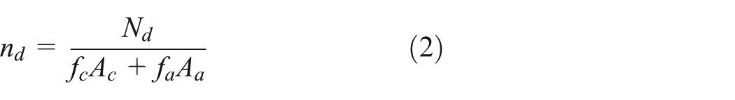
The current standards in China recommend the following conversion coefficient of the design axial compression ratio and the test axial compression ratio

where nt is the test axial compression ratio;
where

The conversion coefficient of the characteristic compressive strength and the design compressive strength is presented as follows in accordance with GB50010 (2010)[15]


where

The conversion coefficient is provided as

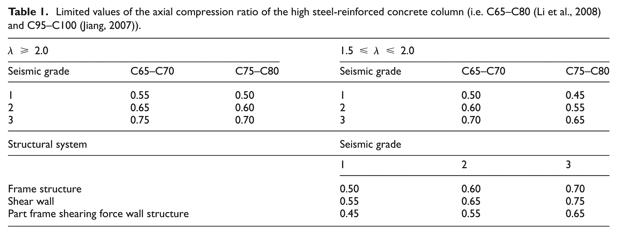
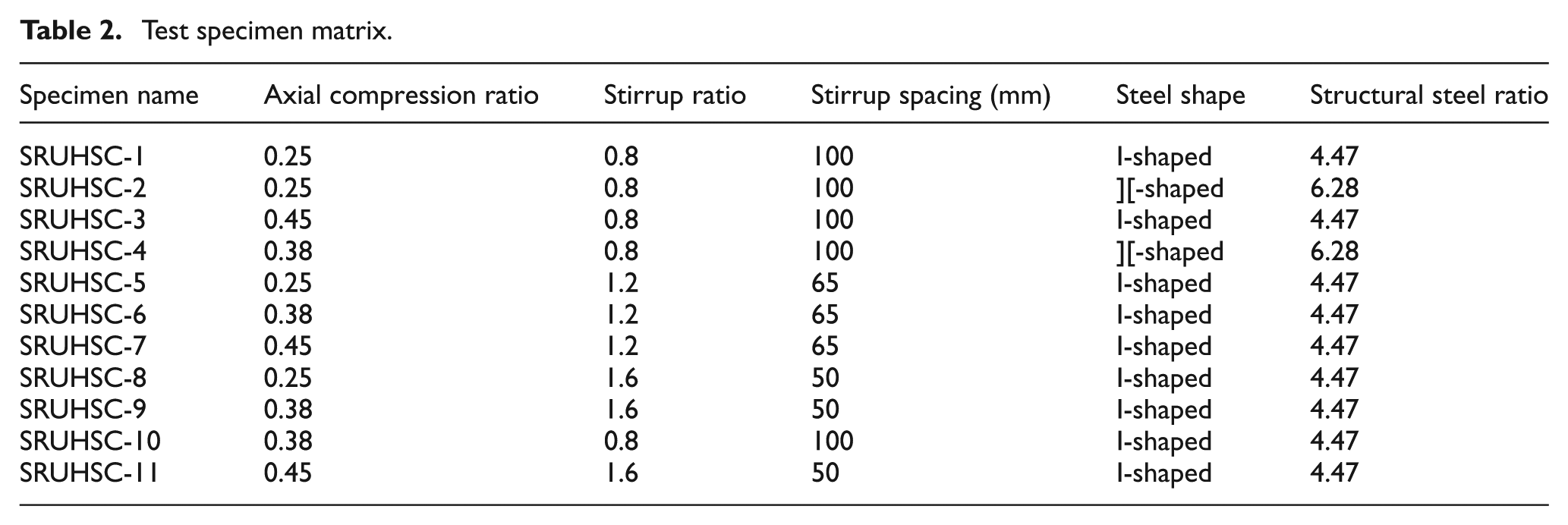
The authors considered the following conditions with respect to the preferences of the axial compression ratio: 0.25 is the axial stress level when the balance is destroyed and 0.38 is the limited value of the axial compression ratio in the existing literature (Tables 1 and 2).
Limited values of the axial compression ratio of the high steel-reinforced concrete column (i.e. C65–C80 (Li et al., 2008) and C95–C100 (Jiang, 2007)).
Test specimen matrix.
The design limited value of the axial compression ratio (i.e. 0.55–0.70) was converted to the test limited value of the axial compression ratio (i.e. 0.32–0.40) based on equation (7). Hence, 0.38 was an axial compression ratio grade, and 0.45 was an axial stress level for the unpredictable list that may appear in an earthquake. The corresponding axial load of 0.45 was 190 t, which was close to allowable maximum axial pressure values in existing laboratory conditions. The existing jack maximum tonnage of the laboratory was 200 t.
Specimen design
The shear reinforcement at the joint was calculated based on the bending moment of the beam to ensure the joint failure. First, the ultimate shear capacity of the joint was calculated based on JGJ 138-2012 (2012). Second, the ultimate flexural capacity of the beam was calculated based on JGJ 138-2012 (2012). Third, the test shear capacity of the joint was calculated according to the force equilibrium condition. Table 3 shows details on the 11 beam–column joint specimens subjected to cyclic lateral loading. The main parameters analyzed included the axial compression ratio nt (i.e. 0.25, 0.38, and 0.45), stirrup ratio ρsv (i.e. 0.8%, 1.2%, and 1.6%) in the joint core, and the ratio of structural steel (i.e. 4.47% and 6.28%) in the joint core.
Mechanical properties of the steel reinforcement and the structural steel.

The beams and the columns had cross sections of 160 mm × 300 mm and 200 mm × 200 mm, respectively. Figure 1(a) shows the layout of the longitudinal reinforcements and the spacing of the stirrup reinforcements. The concrete compressive strength resulting from the compression tests of 10 cubic specimens with a dimension of 150 mm was 112 MPa. Having a dimension of 1.02 m in length and 1.5 m in height, all the specimens contained the same amount of longitudinal and stirrup reinforcements with a concrete cover of 20 mm. Tables 2 and 3 list the material properties, including the yield stress fy and the ultimate stress fu values of the longitudinal steel bar and the stirrup bar.
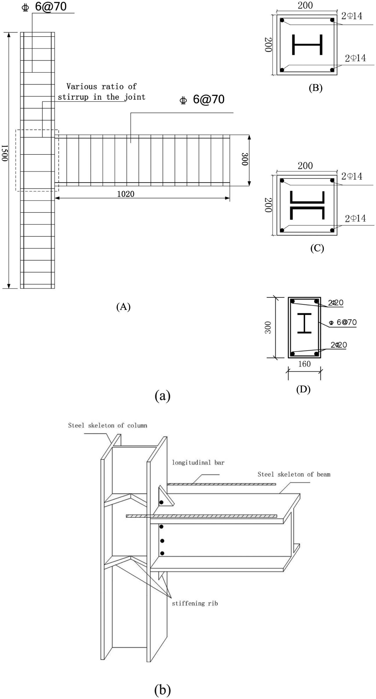
Details of the test specimens: (a) geometry and reinforcement details of the test specimens (unit: mm)—(A) joint configuration, (B) column configuration for the I shape, (C) column configuration for the ][ shape, and (D) beam configuration—and (b) detailed information on the construction in the joint zone.
Test setup and procedures
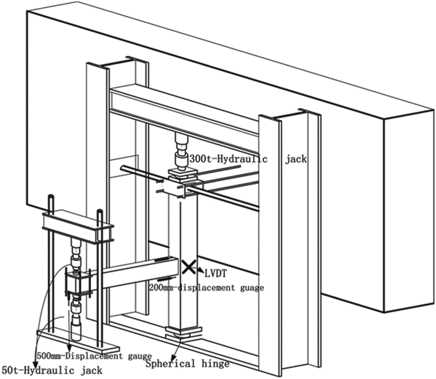
Figure 2 shows that the experimental setup consisted of two 500-kN hydraulic jacks at the beam ends to simulate the lateral load and a 3000-kN hydraulic jack on top of the column to simulate the constant axial load.
Test setup for all the specimens.
The column was hinged at both ends to restrain the potential in-plane and out-plane displacements, where as the beam end was free to move. The axial load was applied to the column through the 3000-kN hydraulic jack to enforce a constant axial compression ratio generated by the weight of a few stories above the studied column. Note that the simulated reversed cyclic lateral load was vertically applied by pulling and pushing the beam end.
The displacements at various locations in each specimen were measured by two linear variable differential transformers, two 200-mm displacement gauges, and two 500-mm displacement gauges (Figure 2). All the specimens were loaded under a force control mechanism before yielding and under a displacement control mechanism for the post-yielding stage. Figure 3 shows the adopted loading history, in which the loading was repeated once at each control point before the specimen yielded and repeated twice at each control point to obtain the degraded restoring force curves after the specimen yielded.
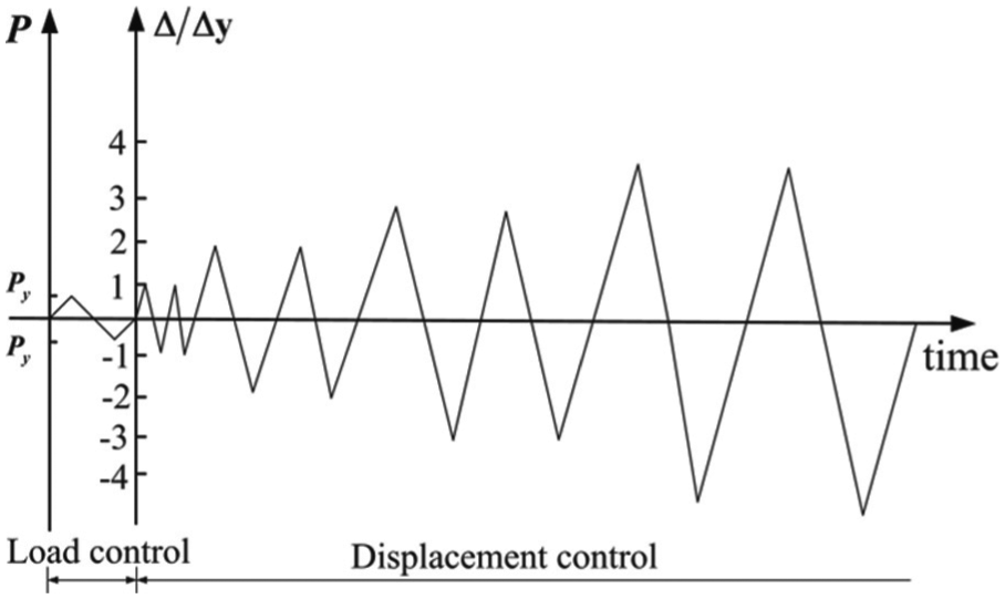
Loading history.
Crack pattern and failure mode
The specimen cracks in the experiment can be divided into three categories. The first type of cracks is the diagonal and vertical cracks caused by the shear force and the bending moment in the beams, respectively. The second type of cracks is the diagonal cracks in the joint core region caused by the principal tensile stress. The third type included cracks in the corner of the beam–column joints caused by the bond slip of the beam longitudinal reinforcement and the vertical cracks in the beams adjacent to the joint core area.
For the first set of specimens, including SRUHSC-1, SRUHSC-2, and SRUHSC-5 with an axial compression ratio of nt = 0.25, cracking of the concrete at the end of the beam was first observed when the lateral force reached a positive 30 kN. The diagonal cracks in the joint were observed at a 1% story drift accompanied by a yielding of the beam longitudinal bars. Two major diagonal cracks were identified in the joint region with the increase in the lateral load. Each crack appeared at the corner of the joint and extended diagonally to the exterior column surface. The concrete in the joint core began to crush, corresponding to a 5% story drift. Moreover, the tendency gradually developed with the increase in the displacement amplitude. Figure 4(a) illustrates the shear failure mechanism formed at the joint core. A different cracking pattern was observed in SRUHSC-8 (nt = 0.25 and ρsv = 1.6) because of the transverse reinforcement in the joint. A cracking pattern similar to that of the aforementioned specimens was formed at the beam end in the elastic stage. Furthermore, several inclined hairline cracks were noticed at the 1% story drift. An extensive number of inclined cracks kept forming in the joint when the specimen began to sustain an inelastic deformation. The hairline diagonal cracks were also distributed over the joint region by the end of the test (6% story drift). Note that the local buckling of the steel compressive flange adjacent to the joint core region also occurred, and the concrete at beam end started to spall off at the 5% story drift. Finally, a typical flexural failure mechanism with a plastic hinge formed at the beam end (Figure 4(b)).
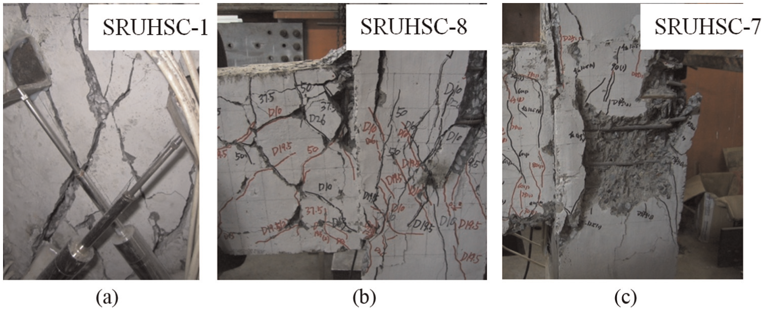
Crack pattern: (a) SRUHSC-1, (b) SRUHSC-8, and (c) SRUHSC-7.
The second set of specimens specified the constant axial compression ratio of nt = 0.45 (SRUHSC-3, SRUHSC-7, and SRUHSC-11). The formation of the diagonal cracks in the joint core was delayed compared with the first set of specimens. Although the diagonal cracks began to appear at the 1% story drift similar to that in the first set specimens, the growth of the diagonal cracks was rapid, and the joint diagonal cracks expanded vertically above and below the joint along the direction of the column steel flange. This led to concrete spalling and severe damage in the joint region at a 2% story drift (Figure 4(c)). Specimen SRUHSC-11 (nt = 0.45; ρsv = 1.6) followed the crack pattern of specimen SRUHSC-1.
The third set of specimens consisted of SRUHSC-6, SRUHSC-9, and SRUHSC-10 with nt = 0.38. The shear failure at the joint cores for both SRUHSC-6 and SRUHSC-10 occurred after a joint yielding and an extensive development of diagonal cracks. However, the degree of damage in the connection of the specimen SRUHSC-9 was reduced because of the 50% higher stirrup ratio compared with that of specimen SRUHSC-10. The strength of specimen SRUHSC-9 was governed by the flexural capacity of the beam and the flexural failure with the plastic hinge formed at the end of the beam.
Results and discussion
Load versus displacement hysteresis loops
Figure 5 graphically illustrates the load–displacement hysteretic behaviors for the 10 specimens to study the mechanical performance of the SRUHSC beam–column joints. All the hysteresis loops of the specimens were plump with no evident pinching effect, which can be explained with two reasons. On one hand, the structural steel in the specimen can effectively restrain the crack growth. On the other hand, the structural steel may be capable of providing the specimens with extra stiffness as the stiffness deterioration occurs in the subassemblies because of the development of microcracks (Ho et al., 2014; Yao et al., 2014). Compared to specimens SRUHSC-1, SRUHSC-5, and SRUHSC-6, a better ductility, loading capacity, and energy dissipation capacity can be observed in the hysteresis curve of SRUHSC-8. This finding indicated that the specimens with a flexural failure at the beam end were superior to those with a shear failure in the joint region. A total of 14 cycles were applied to SRUHSC-5, with a maximum displacement of 65 mm. SRUHSC-6 was subjected to 10 cycles with a maximum displacement of 45 mm. Meanwhile, SRUHSC-7 was subjected to eight cycles with a maximum displacement of 20 mm. In summary, the specimens were basically within their elastic limits before the lateral load of 75 kN and experienced stable yielding between 80 and 85 kN.

Hysteresis loops: (a) SRUHSC-1, (b) SRUHSC-2, (c) SRUHSC-3, (d) SRUHSC-4, (e) SRUHSC-5, (f) SRUHSC-6, (g) SRUHSC-7, (h) SRUHSC-8, (i) SRUHSC-10, and (j) SRUHSC-11.
The maximum lateral loads in the positive and negative directions are defined as
Skeleton curves
The skeleton curves of the specimens can be obtained from the hysteresis curves to predict the variation of the load-carrying capacity and ductility. Figure 6(a) and (b) shows the skeleton curves of the specimens with various axial compression ratios. The increased axial loads had beneficial influence on the carrying capacity of the specimens as the axial compression ratio increased from 0.25 to 0.38 because the axial load increased the depth of the column concrete compression zone. However, note that the effect was not obvious. The reason for this was the axial load increasing the area of the concrete compression zone and the diagonal angle and the decreasing cosine value of the diagonal angle. Therefore, the
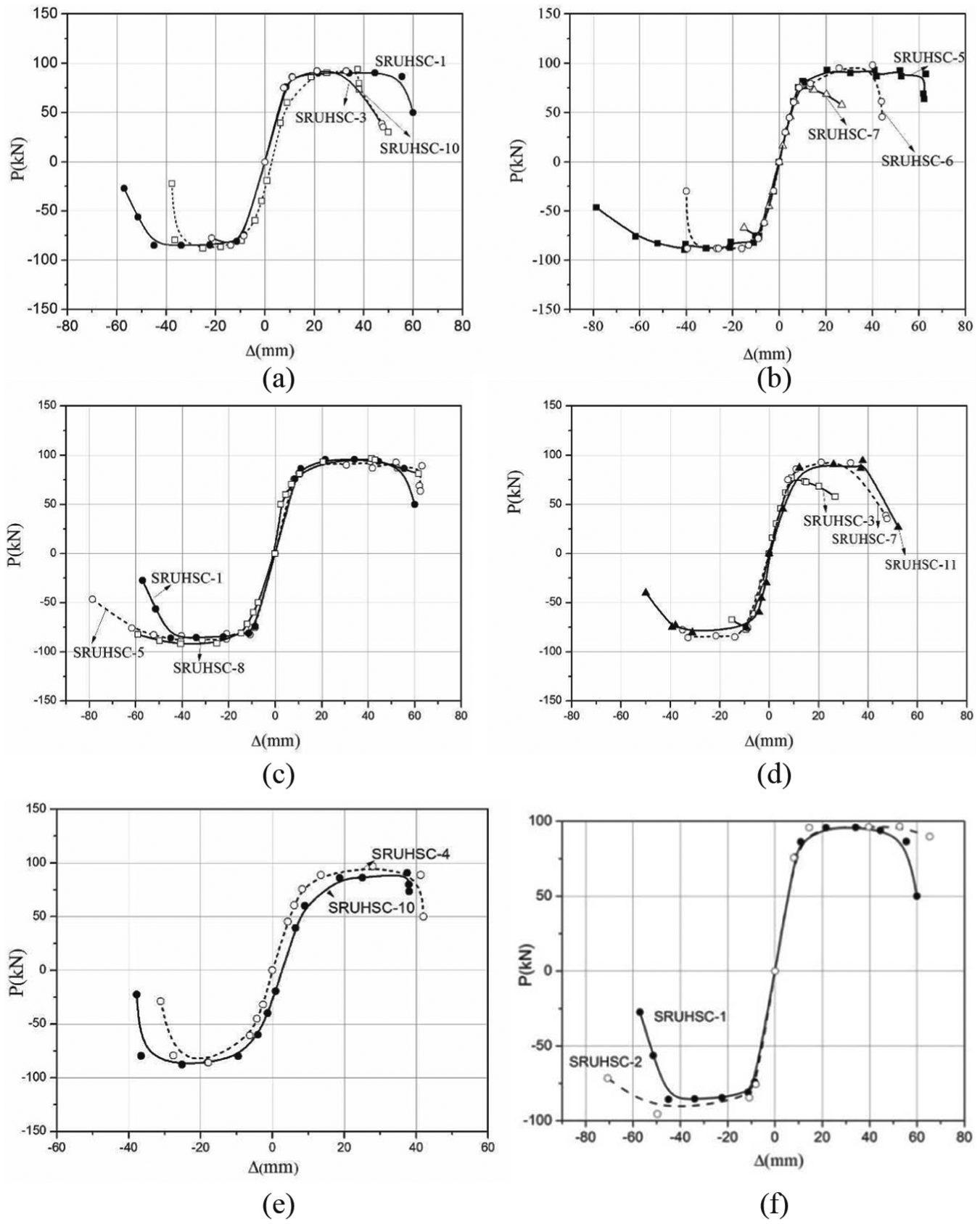
Skeleton curves of the specimens: (a) and (b) shows the skeleton curves of the specimens with various axial compression ratios. (c) and (d) presents the skeleton curves of the specimens with various stirrup ratios.(e) and (f) shows the skeleton curves of the specimens with various structural steel ratios.
Figure 6(c) and (d) presents the skeleton curves of the specimens with various stirrup ratios that indicated that the increased stirrup ratio had a favorable influence on the load-carrying capacity of the specimens. This result can be explained from two perspectives. On one hand, the increase in the stirrup ratio enhanced the confinement effect on the concrete and improved the effective compression strength. On the other hand, the shear strength resistance of the stirrups improved because of the increased effective stirrup areas.
Figure 6(e) and (f) shows the skeleton curves of the specimens with various structural steel ratios. Figure 6(e) depicts that the structural steel ratio increase resulted in the increase in the load-carrying capacity of the specimens. Li et al. (2011) found that a higher steel ratio can cause a higher initial stiffness. Accordingly, a higher initial stiffness can cause a higher peak load. However, increasing amplitude decreased with the increase in the axial compression ratio (Yin et al., 2013), which could be explained by the effect of the structural steel ratio on the initial stiffness and the shear strength being unobvious (Figure 6(e) and (f)).
Ductility
The inelastic deformation was quantified by the displacement ductility µΔ to compare the ultimate deformation capacity of the SRUHSC exterior joints. The displacement ductility µΔ is defined as follows based on the characteristic of the hysteretic responses of the SRUHSC exterior joints (Liu et al., 2015)
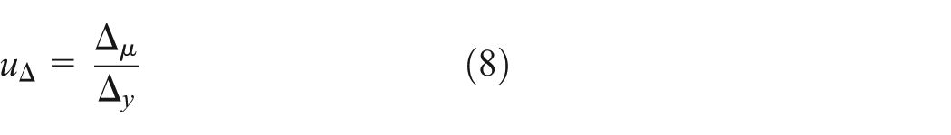
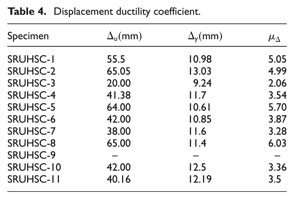
where Δ µ and Δ y are the ultimate and yielding displacements, respectively. Δ µ is defined as the post-spalling displacement, where the residual lateral force has declined to 85% of Fmax, depending on the final failure mode. Table 4 lists the displacement ductility coefficients of all the specimens. Encasing the structural steel into the SRUHSC frame was an effective method of enhancing the shear ductility. These results can be explained by two reasons: the structural steel can improve the stiffness of the specimens and the presence of the structural steel prevents the sudden failure of the specimens and allows capacity degenerating at a slower rate in the post-peak region. Figure 7 shows that the axial compression ratio and the stirrup ratio can significantly influence the specimen ductility. The specimens with the lowest axial compression ratio exhibited a full ductile behavior and an excellent load-carrying capacity to sustain a large inelastic cyclic displacement without sudden failure. Note that the shear ductility value dropped by 57% when the axial compression ratio increased by 80%, indicating a negative axial-loading effect on the inelastic cyclic behavior of the column.
Displacement ductility coefficient.

Schematic diagram of the
The indices demonstrated that the increase in the axial compression ratio (increase in the compression stress of the cross section) will lead to a drop in both the ductility and the load-carrying capacity of the specimen. For a higher axial compression ratio, the shear stress tended to increase to the failure stress before the bending displacement was fully developed.
Table 4 shows the effect of the stirrup ratio on the shear ductility. The shear ductility value increased by 20% with the stirrup ratio increase. Similarly, among specimens SRUHSC-3,SRUHSC-7, and SRUHSC-11 with the same axial compression ratio of nt = 0.45, SRUHSC-11 (with a higher stirrup ratio) exhibited a better shear ductility than SRUHSC-3 (Figure 6(d)). The positive effect of the stirrup ratio on the shear ductility was basically caused by the tying effect of the stirrup by restricting the development of diagonal cracks. An increase in the stirrup ratio also enforced a decrease in the slip between structural steel and ultra-high-strength concrete to ensure that the latter will coordinately work well with the structural steel, demonstrating the positive effect of the stirrup ratio on the specimen’s shear ductility.
Yan et al. (2010) reported that the shape of steel can affect the ductility of the joint specimens, and the specimens with a  steel shape had a better ductility than specimens with a
  steel shape because of better confinement. However, the effect of improving the volumetric ratio of the steel confinement on the shear ductility of the joint with the similar steel shape was not obvious in this study.
Dissipation capacity
The energy dissipation capacity is an important index in evaluating the structure’s seismic performance. The energy dissipated by the structure for the ith cycle has been defined as the hatched area in Figure 7 and can be expressed as follows

Note that the energy dissipation capability can be indicated by the equivalent damping ratio

where

Figure 8 shows the curves of

Energy dissipation capacities of the specimens: (a)
External actions and internal shears at the exterior joint: (a) global equilibrium in the exterior beam–column joint and (b) internal shears at the exterior joint.
Shear strength of the joint core
Equilibrium of the ultimate external forces and the internal shear strength
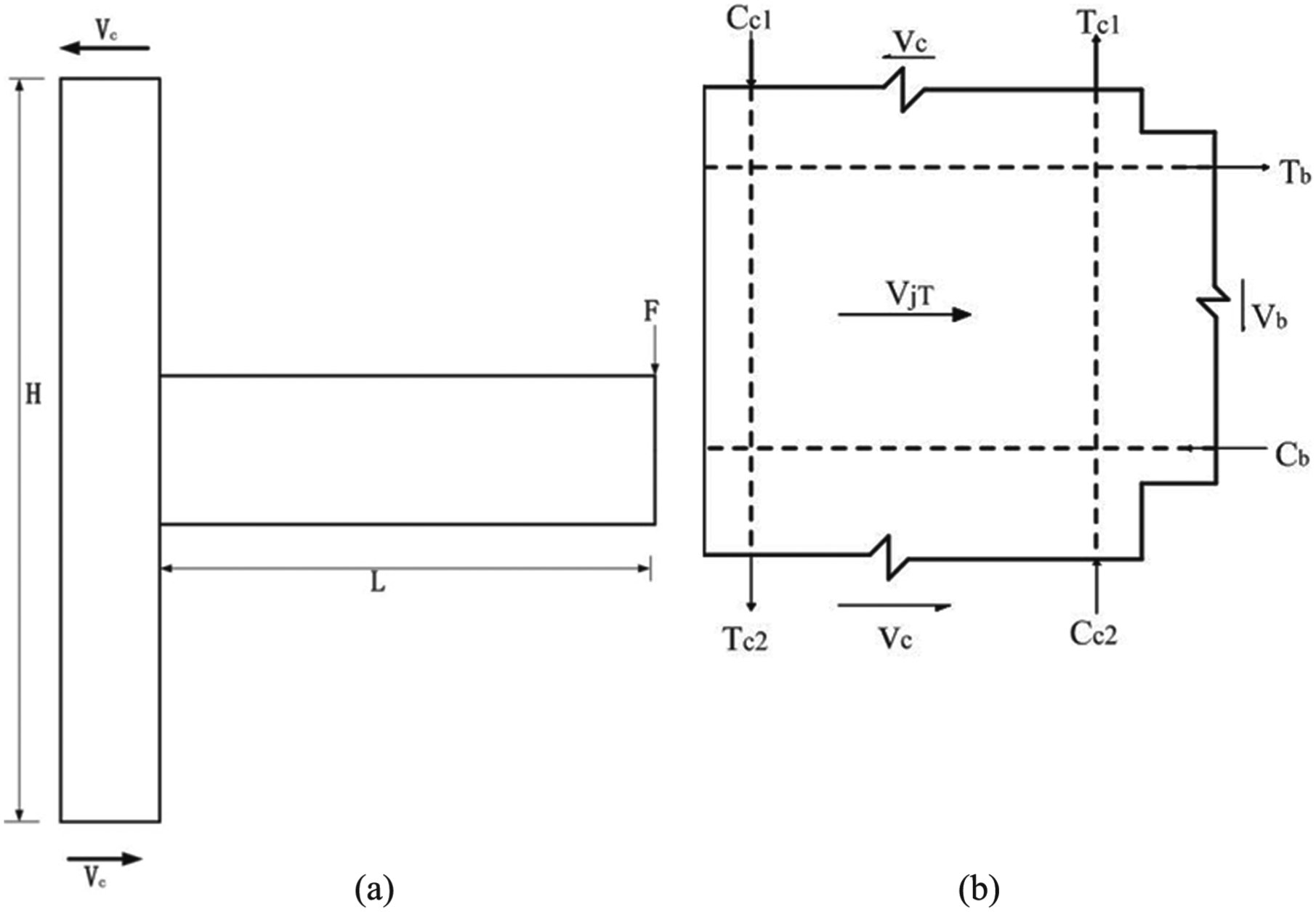
Figure 9 shows the earthquake-induced forces acting on the exterior joint. The horizontal joint shear force was estimated using the notation (Figure 9) and expressed as follows.
The equilibrium of the horizontal forces yielded the following equilibrium equation based on the moment balance
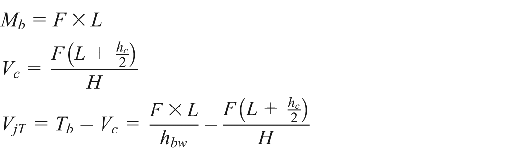
where Mb is the bending moment of the beam; Vc is the column shear forces; L is the length from the beam inflection point to the column face; H is the height between the upper and lower column inflection points; hc is the section height of the column; VjT is the horizontal joint shear force; Tb is the tensile force resulting from the steel of the beam; and Vc is the horizontal column shear force above the joint. For the steel-reinforced concrete beam, hbw is generally defined as the distance between the tensile steel flange and the compression steel flange (Fukuhara and Minami, 2008; Sangjoon and Khalid, 2012; Tian, 2015; Yan et al., 2010).
Effective shear strengths by three mechanisms
The shear strength of the joint core can be evaluated using the strength superposition method (Park and Mosalam, 2012). The shear strengths contributed by the steel, concrete, and stirrups were first calculated separately before being superposed to obtain the joint shear strength.
Horizontal shear strength of the steel web panel
The effective shear strength contributed by the shear mechanism Vw of the steel web panel can be calculated as follows using equation (12), which was proposed by Parra-Montesinos (2001a)
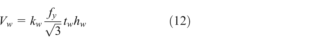
where
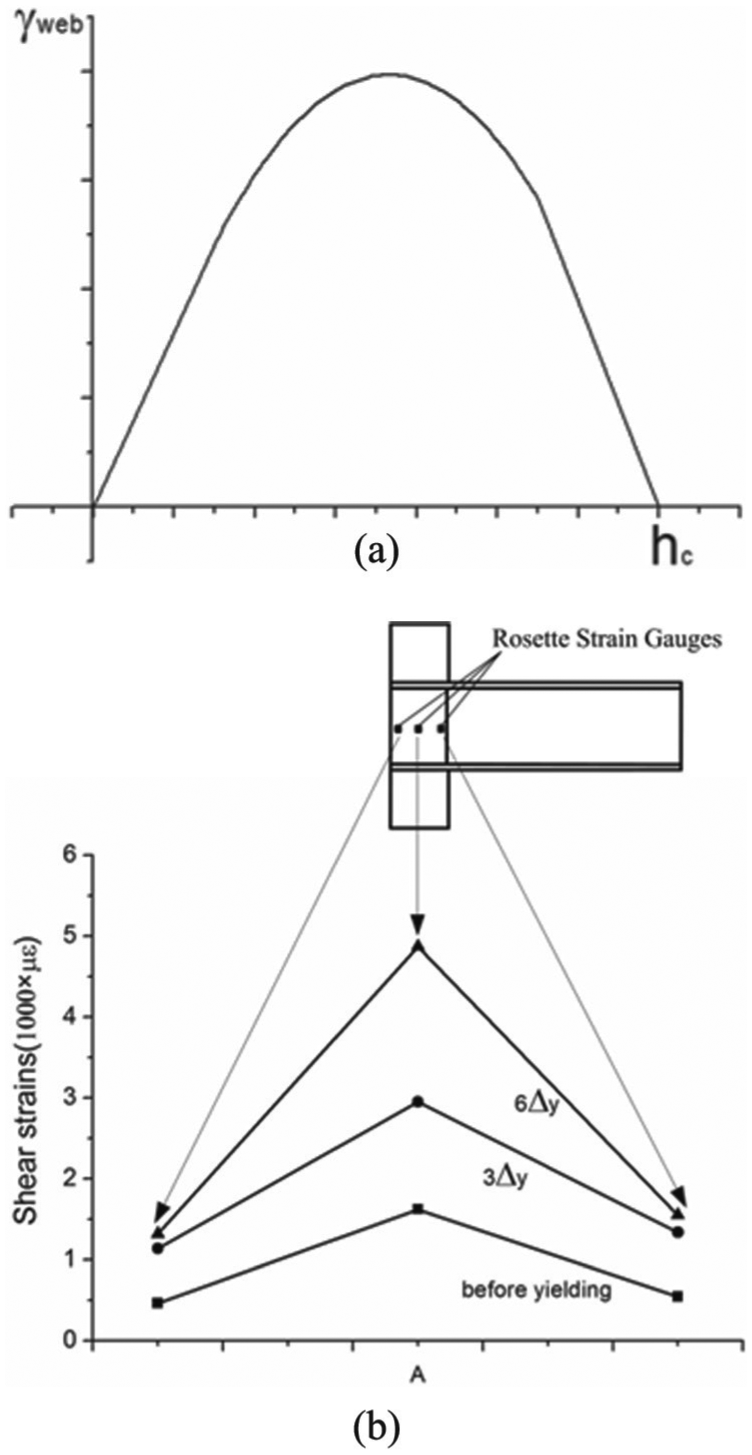
(a) Distribution of the shear strains in the steel web panel (Parra-Montesinos et al., 2012) and (b) strains at the three different locations in the steel web panel.
Concrete compression strut
The concrete compression strut can be divided into an inner concrete compression strut and an outer concrete compression strut because of the joint confinement (Figure 11).
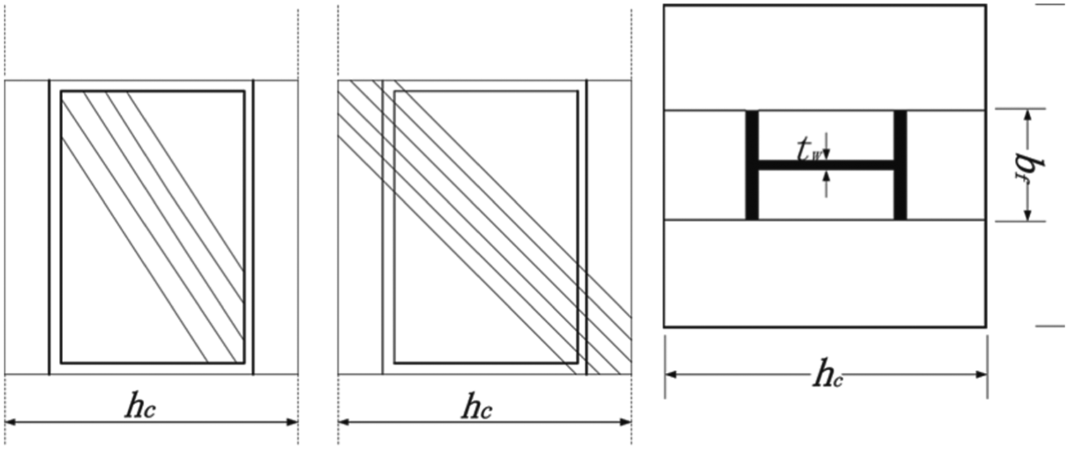
Concrete diagonal struts.
The inner concrete compression strut mechanism was activated by the bearing of the column steel flange and web stiffeners. The compression strut was approximately assumed to have a depth of 30% of its length (Tang and Chen, 1990), such that the effective shear strength contributed by the inner concrete compression strut and the outer concrete compression strut can be obtained as follows


where

The effect of the transverse tensile strains on the concrete softening was considered herein by factor
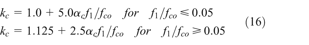

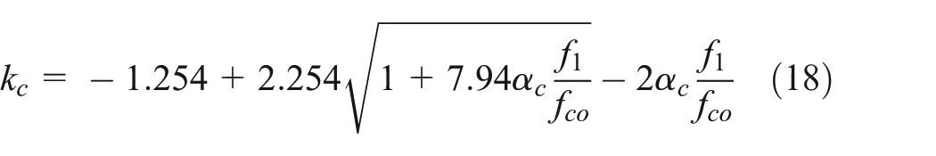
The result showed that the computation for well-confined members may exceed a value of 2.0. Hence, a value of 2.0 can be a lower limit of kc (Parra-Montesinos and Wight, 2001b). This was relatively high compared to a RC section of the same dimensions and of a similar reinforcement detailing, which would provide a value of 1.0–1.2. Hence, kc = 2 was used conservatively for the inner concrete, which was well confined (Zhu, 2013). A value of kc = 1.1 was used for the outer concrete, which was partially confined.
Vecchio and Collins (1993) proposed a softening parameter
where
Shear strength contributed by the stirrups
The measurements of the linear strain gauges attached to the stirrup legs parallel to the loading direction indicated that most of the stirrups behaved elastically before the beam bended. Figure 12(a) plots the average strain measured in the joint transverse reinforcement of five specimens for various lateral load levels. The indices showed that the contribution of the confinement stirrup to the concrete played a dominant role at the elastic stage. However, the contribution of the shear resistance property significantly increases after the occurrence of diagonal cracks in the joint.

Strains in the joint stirrups: (a) strains of various specimens and (b) strains in various positions.
The effect of the bond force distribution was not an important variable compared with the strength of the exterior beam column joints, in which bond failure did not occur. The shear strength of the stirrups can be expressed as follows

where
Verification and discussion
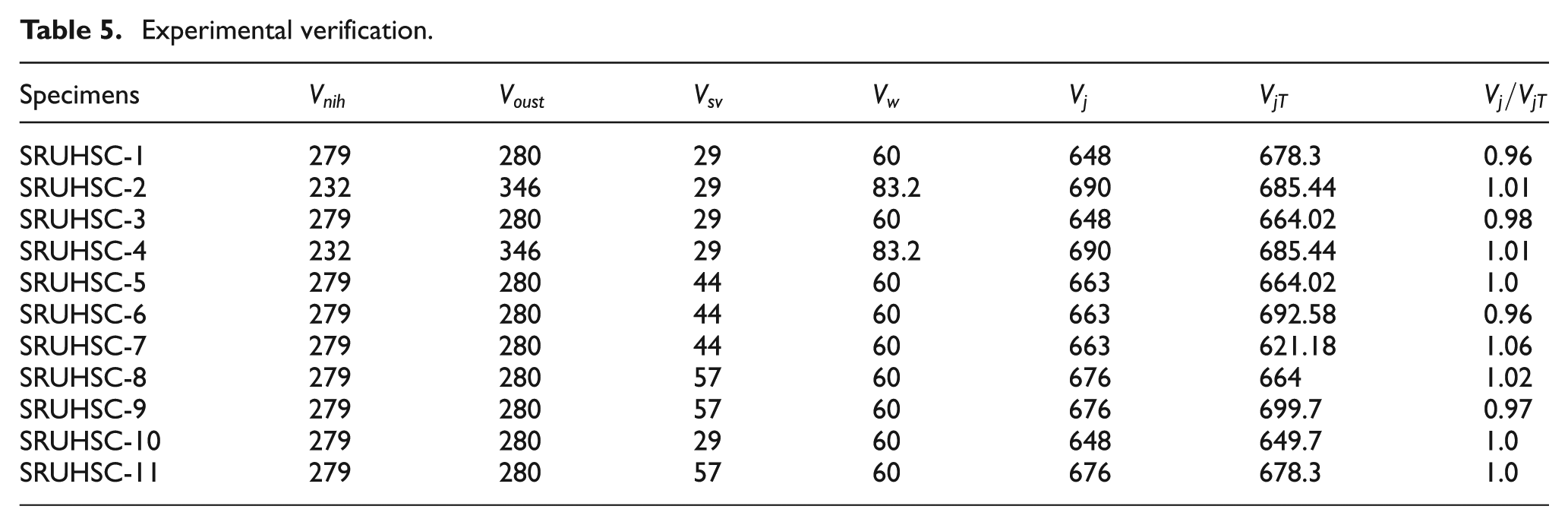
The ultimate shear forces of the specimens at the beam inflection point caused by the shear failure at the joint cores can be calculated using the proposed superposition method. Table 5 lists the predictions of all the specimens.
Experimental verification.
Effect of the ultra-high-strength concrete
The ultra-high-strength concrete provides superior durability, low permeability, high resistance to abrasion, and reduced shrinkage and creep (ACI). The ultra-high strength of concrete allows a size reduction of the structural members, while the corresponding weight reduction will further decrease the inertial force in earthquake regions. The proportion of strength among concrete, structural steel, and stirrup shows that the concrete bears most of the shear strength. However, the softened coefficient decreased with the increase in the concrete strength grade because of the principle tensile strain reducing the principal compression strain. Hence, strengthening the constraints is important in ensuring a good seismic behavior of the ultra-high-strength concrete structures.
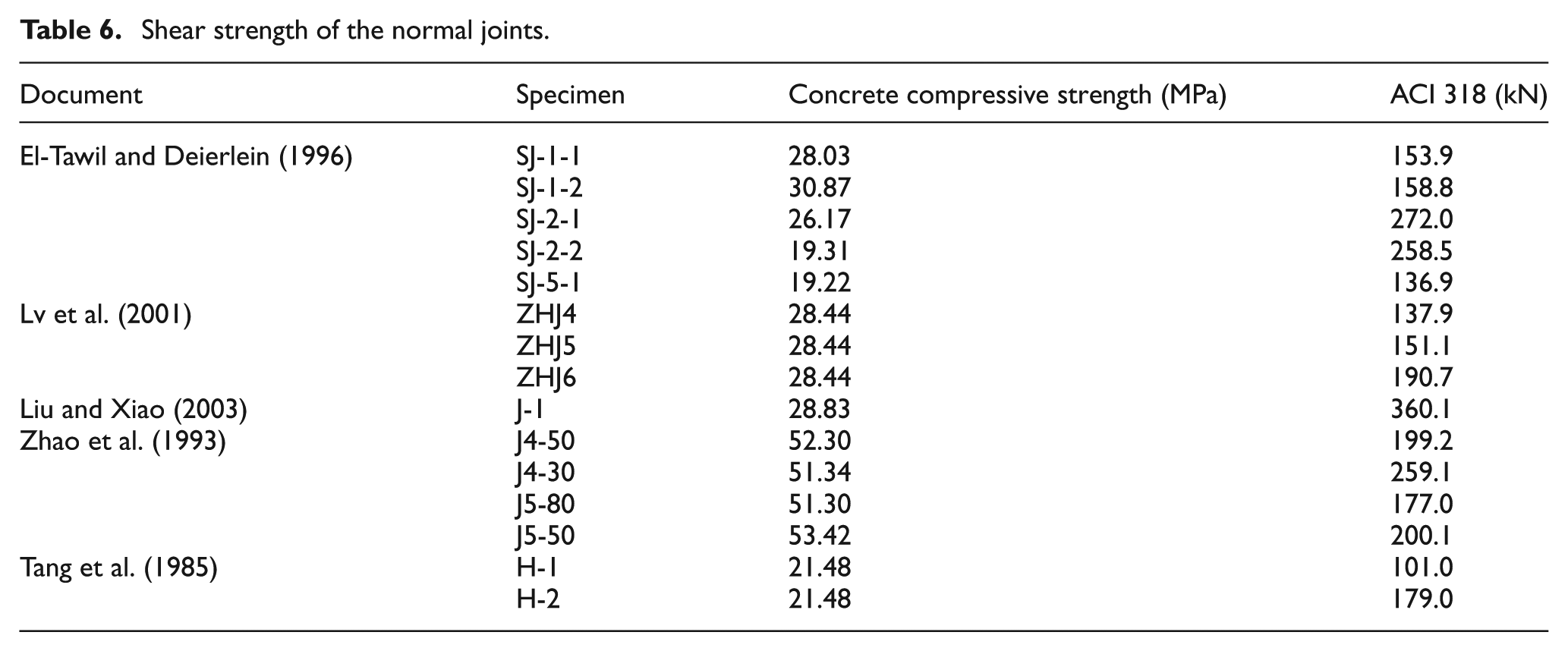
The shear strength of the normal joints with sizes similar to the test joints in this article was calculated by ACI 318 (Table 6). Compared with the shear strength of the hybrid joints in this study, the shear strength of the hybrid joints with structural steel was improved five times.
Shear strength of the normal joints.
Conclusion
This study conducted pseudo-static reversed cyclic tests on 11 specimens to investigate the mechanical properties of the SRUHSC beam–column joints subjected to earthquake loading and better understand the seismic behavior of the beam–column joints. The main test variables were the axial compression ratio, stirrup ratio, and ratio of structural steel. The test focused on the cracking pattern, hysteretic behavior, load-carrying capacity, shear ductility, energy dissipation, and stiffness degradation of the SRUHSC beam–column joints. The following conclusions were drawn from the experimental results described in this article:
The test results of the specimens indicated no essential change in the failure modes as the axial compression ratio increased, but the specimens were more inclined to be subject to brittle failure with the decrease of cracks. The damage of the joint core area was more serious for the lower axial compression ratio, with more damage occurring in the plastic hinge regions of the adjacent beams. Most of the damage occurred in the joint core area for the specimens with a higher axial compression ratio.
The load versus the displacement relationship (hysteresis loops) of each specimen was graphically illustrated. All the hysteresis loops were plump without an evident pinching effect, thereby indicating that the structural steel significantly improved the seismic behavior of the beam–column joints.
As regards the SRUHSC exterior joints, an increase within 0.38 of the axial compression ratio can improve the load-carrying capacity of the beam–column joints. However, this load-carrying capacity will decrease when the axial compression ratio increases to 0.45. The increase in the stirrup ratio and the ratio of structural steel had a positive influence on the shear capacity of the specimens.
The safe use of the SRUHSC specimens in seismic zones depended on the association of the required ductility with the confinement detailing and the amount of transverse reinforcement. The specimens with a low axial compression ratio had an excellent seismic behavior characterized by sufficient energy dissipation and deformation capacity even when confined with less transverse reinforcement. A significant amount of transverse reinforcement was necessary when the subassemblies were subjected to a high axial compression. The influence of the volumetric stirrup ratios confined with joints on the deformation capacity was more remarkable, especially under high axial compression conditions.
The model used to derive the design formula for the shear strength of the joint core in the analytical research comprising the inner concrete compression strut, outer concrete strut, steel web panel shear, and stirrup mechanism can accurately predict the actual shear strength of the test joints.
Footnotes
Declaration of Conflicting Interests
The author(s) declared no potential conflicts of interest with respect to the research, authorship, and/or publication of this article.
Funding
The author(s) disclosed receipt of the following financial support for the research, authorship, and/or publication of this article: This work was supported by the National Natural Science Foundation of China (grant no. 51178078) and the 863 Project of the Ministry of Science and Technology of the People’s Republic of China (grant no. 2007AA11Z133). The authors express their gratitude for this financial support.