



Abstract
This article elaborates on experimental and analytical studies on the behavior of tube-confined steel-reinforced ultra-high-strength concrete short columns subjected to axial compressive load. A total of 22 specimens were fabricated and tested to investigate the failure mode and axial load behavior of tube-confined steel-reinforced concrete columns. The parameters for the tests include the following: (1) tube shape, (2) the shape of inner steel, (3) the thickness of the steel tube, and (4) tube tensile strength. The test results indicate that the confinement effect of the circular tube is greatly superior to that of the square tube, because the circular tube can prevent the ultra-high-strength concrete from brittle failure more efficaciously. The O-shape of the steel exhibited better mechanical performance than other shapes of the steel. The larger the area of the concrete that could be constrained by the steel shape, the better the performance it could provide. Elastic–plastic analysis of the tube was utilized to investigate the mechanism of tube-confined steel-reinforced concrete columns under axial compression. A bearing capacity formula for tube-confined steel-reinforced concrete columns was proposed based on the test results, which can be used as a reference for further study and guideline for engineering application.
Keywords
Introduction
A stringent need to improve simultaneously the load-bearing capacity and ductility of pillars/piers has emerged with the development of high-rise buildings and long-span bridges (Wang et al., 2014). In response, composite structures and high-performance materials, especially concrete-filled steel tube (CFST) structures and high-strength concrete, have been extensively studied in recent years (Patel et al., 2014). However, some disadvantages limit the application of CFST structures in contemporary buildings, such as the complexity of beam–column joints, local buckling of the tube, and poor fireproof performance (Qi et al., 2011; Yu et al., 2010).
“Tubed column” is a new type of composite structure first proposed by Tomii et al. (1985).They studied the mechanical behavior of tube-confined reinforced-concrete columns and proved the excellent earthquake-resistant behavior of this composite structure. This study then attracted vast attention and laid a strong foundation for later researches. Xiao et al. (1986) discussed the design method of tube-confined reinforced-concrete columns, promoting the engineering application of such structure. Elremaily and Azizinamini (2002) explored the behavior of concrete-filled tube columns under seismic loads and found that the confinement provided by the steel tube can significantly improve the bearing capacity of the column.
The critical diagonal shear crack crossing the midrange of the column has been widely accepted as the primary trigger of the failure of tube-confined concrete column. And hence the shear crack should be avoided as far as possible in engineering practice. Wang et al. (2003) proposed to insert a steel section into a CFST and concluded that the combination of the steel tube, concrete, and steel section provides a superior performance in strength, ductility, and capacity of energy absorption. It is found exceedingly effective to impose a steel core in the concrete to improve the shear resistance of a CFST and to retard the spreading of the critical diagonal shear crack. And the load-bearing capacity and inherent ductility of the column would be significantly improved by this way (Luo et al., 2014; Wang et al., 2004). By inserting steel section of different shapes into circular and square tube-confined columns, Zhou and their team (Liu et al., 2009, 2015; Liu and Zhou, 2010; Zhou et al., 2015) systematically analyzed the axial load–bearing capacity and seismic performance of circular and square tube-confined steel-reinforced concrete (CTSRC and STSRC, respectively) columns. In Europe, similarly encased open-section composite columns have been studied by ARBED, a steel- and iron-producing company focusing on the engineering application of composite columns. Figure 1(a) shows the configuration of this composite column with inner steel section. The outward tube is disconnected in the beam–column joint without getting through the joint core region, which means that the essential function of the steel tube is to confine the concrete core, shouldering no axial load directly. By this way, the complexity of beam–column joints of CFST columns is shunned and such column would receive more extensive engineering application.
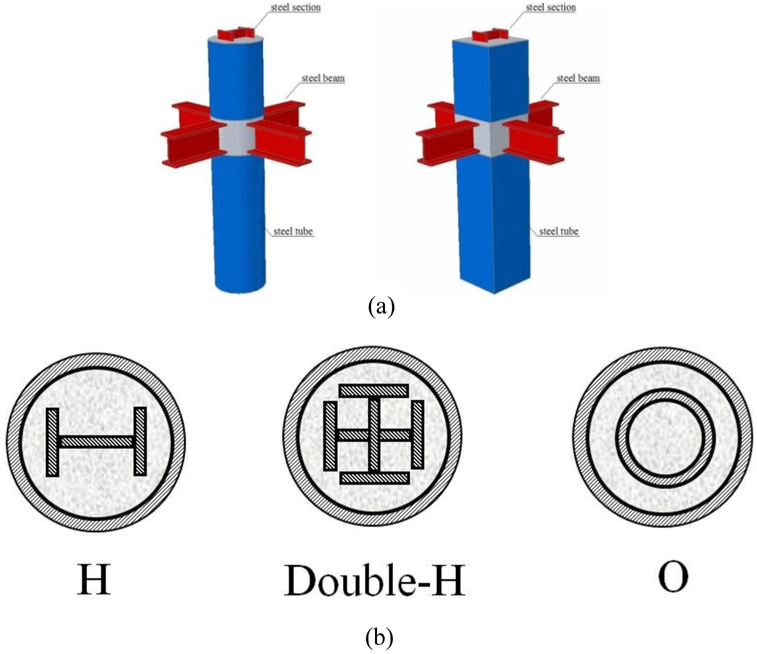
(a) CTSRC/STSRC columns in a structural frame and (b) cross sections of various forms.
Ultra-high-strength concrete, such as C100 concrete, is expected to receive wide application in the field of engineering. The literature review conducted concludes that the research of tube-confined steel-reinforced columns with ultra-high-strength concrete is far from adequate. It is generally acknowledged that high-strength concrete is more brittle than normal one (ACI Committee 318, 2008). Therefore, the research about the behavior of tube-confined steel-reinforced ultra-high-strength concrete short column needs to be further developed.
The main purpose of this article is to investigate the compression behavior of tube-confined ultra-high-strength SRC short column under axial loads. The impact of some parameters on the strength and ductility of the tube-confined SRC columns is explored. These test parameters considered include tube shape, steel shape, the thickness of the steel tube t, and the tensile strength of the tube.
Experimental program
Details of specimens
Theaxial compression tests were implemented on 22 short tubular confined SRC columns, including 2 CFST columns and 20 tubular confined SRC columns (10 circular specimens and 10 square specimens). Details of the specimens are shown in Tables 1 and 2. Four main parameters are accounted for in these tests, including the following:
The shape of the tubes (circular and square);
The shape of inner steel (H-shaped, double H-shaped, or O-shaped);
The thickness of the steel tube t;
Tube tensile strength (Q235 and Q345).
Details of circular short columns.
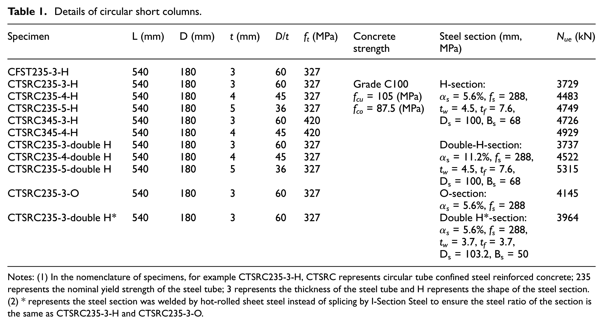
Notes: (1) In the nomenclature of specimens, for example CTSRC235-3-H, CTSRC represents circular tube confined steel reinforced concrete; 235 represents the nominal yield strength of the steel tube; 3 represents the thickness of the steel tube and H represents the shape of the steel section.(2) * represents the steel section was welded by hot-rolled sheet steel instead of splicing by I-Section Steel to ensure the steel ratio of the section is the same as CTSRC235-3-H and CTSRC235-3-O.
Details of square short columns.
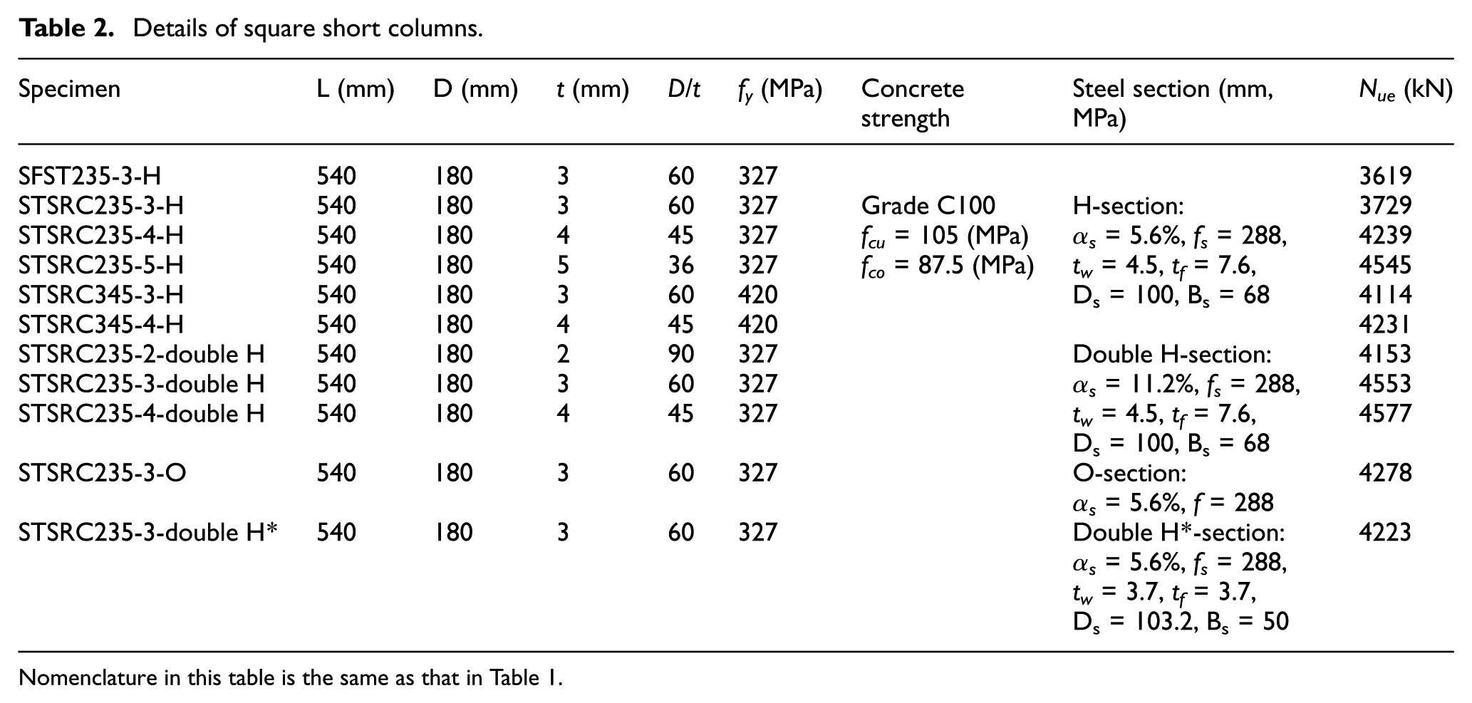
Nomenclature in this table is the same as that in Table 1.
To guarantee the specimen’s short column behavior, the length-to-diameter/width ratio of each column is 3. Two small grooves were cut on the tube near the edges of each specimen to ensure that the tube was not under direct compression during the test and the main role of the tube is to confine the concrete. The cross sections of different steel shapes are depicted in Figure 1(b).
Test setup and instrument layout
All the columns were tested at a 10,000-kN capacity universal testing machine. Figure 2 demonstrates the test setup of the columns. A pair of strain gauges arranged in 90° was attached to the mid-height of the tube to monitor the axial and lateral strains. A total of 16 strain gauges were glued on the external surface of the tube at the top, mid-height, and bottom part, facilitating the observation of the different confinement between the end and middle of the tube. Two linear variable differential transducers (LVDTs) were placed along the specimen to measure the axial deformation.
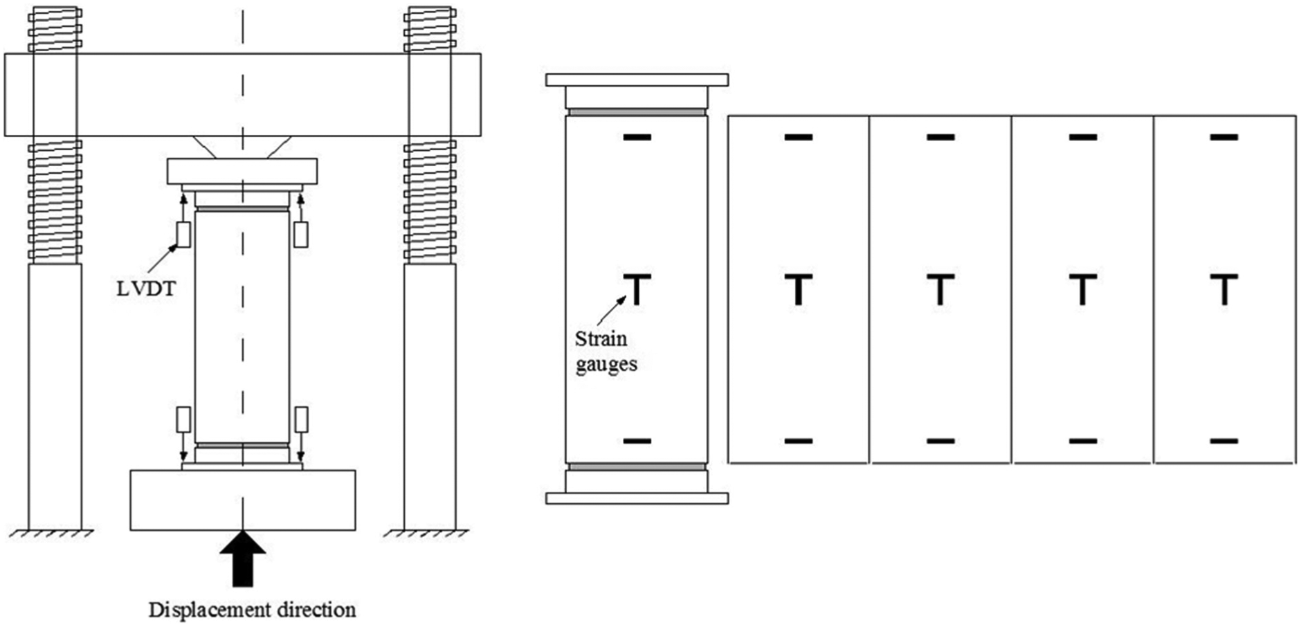
Test setup.
The loading rate for each specimen was set as 0.8 MPa/s before reaching 80% of the estimated load-carrying capacity. And the load interval was kept 8% of the estimated load-carrying capacity during the loading process. Each loading interval was maintained for about 2 min. Then the loading rate changed to 0.16 mm/min until the test was finished.
Experimental results and discussions of CTSRC columns
Failure modes of CTSRC columns
Typical failure modes of CTSRC columns are shown in Figure 3. A line of small bulge was first observed at the surface of the tube. The local bulge started to trigger the failure of the column as loading proceeded. Conformal coating was peeled off from the tube and then a critical diagonal crack occurred on the concrete core, leading to the final failure of the column. Similar shear failure was observed in all the CTSRC columns tested. It is interesting that the cracks on the surface of the concrete almost coincided with the bugles on the tube. These bulges on the tube were produced by the relative slip of the concrete. The inserted steel shape restricted the development of the slip within half side of the cross section; thus, the relative slip of the concrete was tiny, and the deformation of the tube was hardly visible.
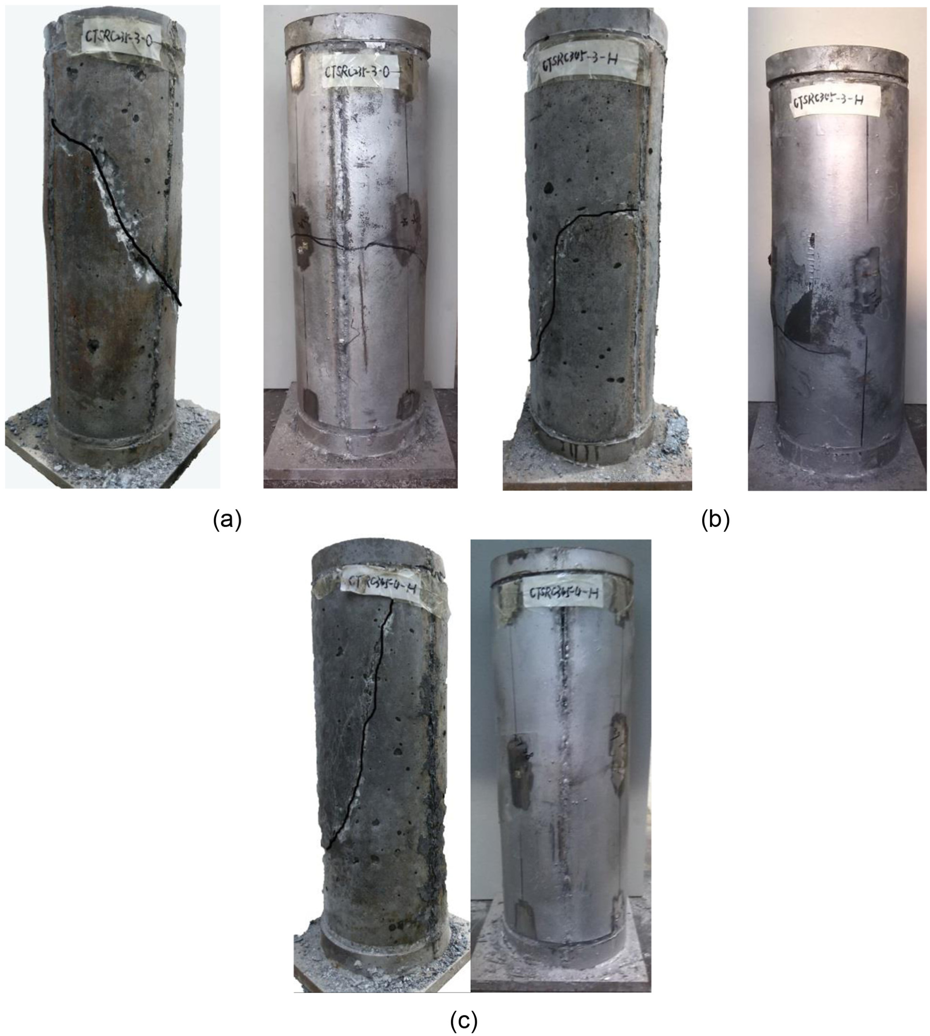
Failure modes of CTSRC columns: (a) CTSRC235-3-O, (b) CTSRC345-3-H, and (c) CTSRC345-4-H.
Load–axial deformation responses of CTSRC columns
Figure 4 shows the load–axial displacement curves (N–Δ) of the test specimens, where Δ is the average displacement measured by the LVDTs. The maximum loads (Nue) obtained in the test are summarized in Table 1. For CFST column, during the initial loading stage, in general, the N–Δ is approximately linear of loading followed by the deterioration in load capacity. Like CFST column, CTSRC columns showed the same linear behavior at the initial stage. However, its maximum load capacity experienced a hardening stage before reaching a degradation that is gentler than CFST column.
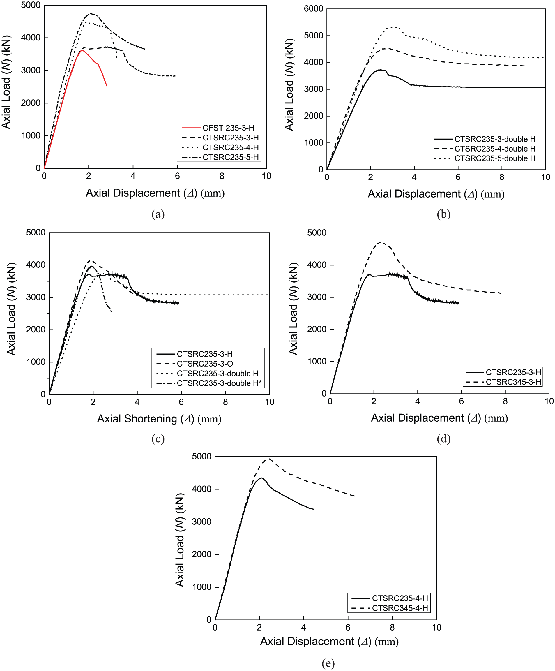
Load–axial displacement curves of CTSRC columns: (a) effect of thickness of steel tube (H), (b) effect of thickness of steel tube (double H), (c) effect of thickness of shape of inner steel, (d) effect of tube tensile strength (t = 3 mm), and (e) effect of tube tensile strength (t = 4 mm).
Load capacity enhancement index (SEI) and ductility index (DI) were calculated to quantify the effect of different parameters on load capacity and ductility, shown in the following. Table 3 shows the SEI and DI values of the specimens obtained from the test results



where Nue and NCFT,ue denote the ultimate load capacity of CTSRC columns and CFST columns, respectively. Δ85% is the axial strain where the load falls to 85% of the ultimate load capacity. Δ y is the yield displacement, and Δ75% is the axial shortening when the load reaches 75% of the ultimate load in the pre-peak state.
SEI and ductility evaluation of circular short columns.
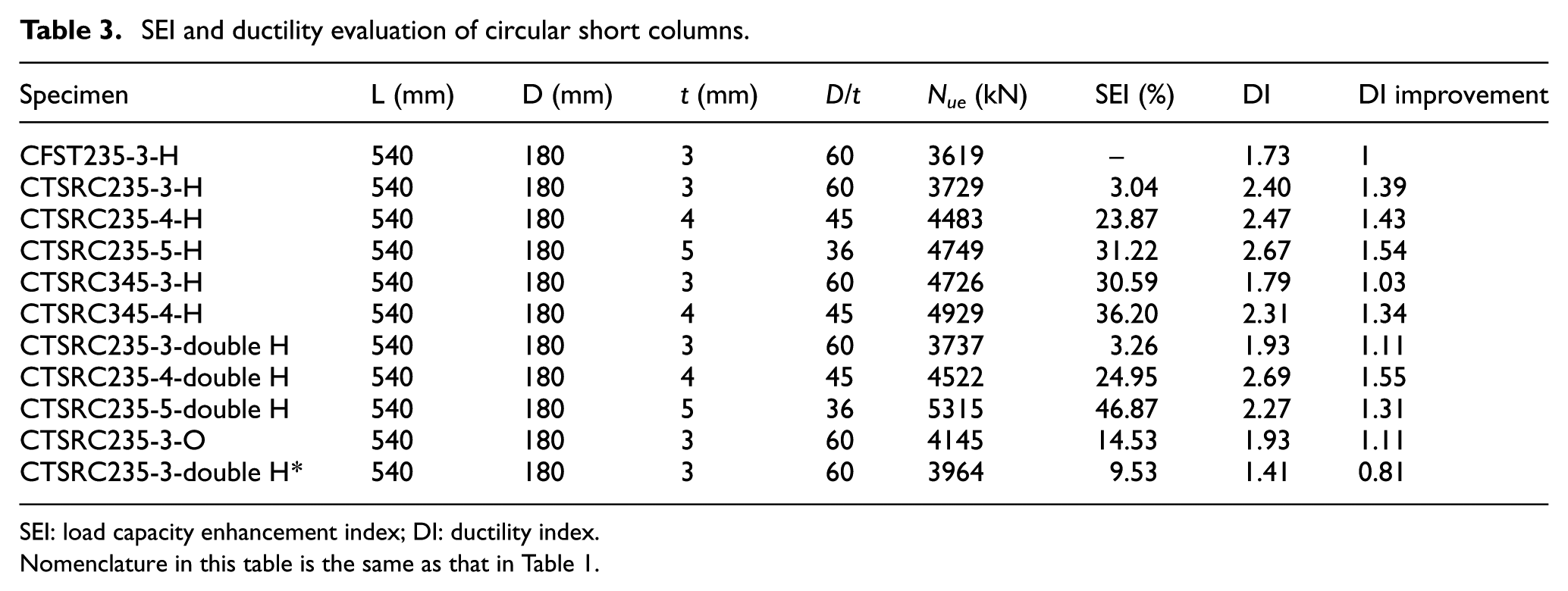
SEI: load capacity enhancement index; DI: ductility index.
Nomenclature in this table is the same as that in Table 1.
From Figure 4(a) and (b), the load capacity of CTSRC columns was improved apparently compared with CFST columns. As also shown in Table 2, it is obvious that the bearing capacity was enhanced with the increase in t due to the magnification of the confinement effect of the tube, and the stiffness of the columns was slightly improved meanwhile. The SEI values of CTSRC 235-3-H, CTSRC235-4-H, and CTSRC235-5-H were 3.04%, 23.87%, and 31.22%, respectively. Figure 4(c) demonstrates the N–Δ curves of the columns with different inner steel shapes and same shape steel ratios. The axial load capacities of CTSRC235-3-double H* and CTSRC235-3-O improved 9.53% and 14.53%, respectively, which showed better bearing capacity than others. Figure 4(d) and (e) compares two groups of specimens with different thicknesses of the steel tube to investigate the effect of tube tensile strength. As expected, the tensile strength of the tube had positive influence on the final compression capacity, which, however, reduced with increasing thickness of the steel tube. The reason may be the tensile strength only dominated in the thin-walled tube (the thickness is lower than 3 mm).
The ductility mattered a great deal on high-strength concrete accounting for the influence of fragility. The superior confinement provided by CTSRC columns can be verified by DI values in Table 3. The DI values of whole CTSRC columns were superior to CFST columns, except CTSRC235-3-double H*. This can account for the welding residual stress in CTSRC235-3-double H*. It is also obvious that the descent stage appeared later and the descend range was smaller in the curves along with the increase in the thickness t in the same shape of inner steel, from Figure 4(a) and (b). Compared with the positive effectiveness in load capacity, the tensile strength of the tube had inconspicuous influence on the ductility.
This conclusion can generally be made from Figure 4 and Table 2: (1) CTSRC columns showed the enhancement of bearing capacity and ductility efficiently due to the better confinement. (2) CTSRC235-3-O showed the best performance comprehensively while CTSRC235-3-H showed the worst. The shape of the steel section does affect the performance of the columns. It can be explained that O-section has the strongest confinement on the concrete surrounded by it while H-section is inferior, and double H-section provides partial confinement on the concrete around it. (3) The tensile strength of the tube has limited influence on the final compression capacity and ductility.
Normalization curve about |εh/εv| of CTSRC columns
The gauges bonded at the mid-height of the specimens measured the horizontal and vertical strains of the tube. For each specimen, four horizontal strains (εh) and four vertical strains (εv) were recorded and the relation of the average horizontal and vertical strains with the load is shown in Figure 5. The connections of such structural members can be observed from the normalization curve compared with CFST column about |εh/εv| (Figure 6). It is obvious that when the load was less than 0.2Nu, the |εh/εv| of CTSRC stayed around 0.29, equal to the Poisson’s ratio of steel. The frictional force in the longitudinal direction was the primary force between the steel tube and the concrete in this stage. Later on, the numerical value of |εh/εv| increased suddenly in CTSRC compared to the constant approximately in CFST. It demonstrated that the confinement effect of CTSRC was stronger than CFST, and the confinement provided by the steel tube of CFST was inefficient in the early stage.
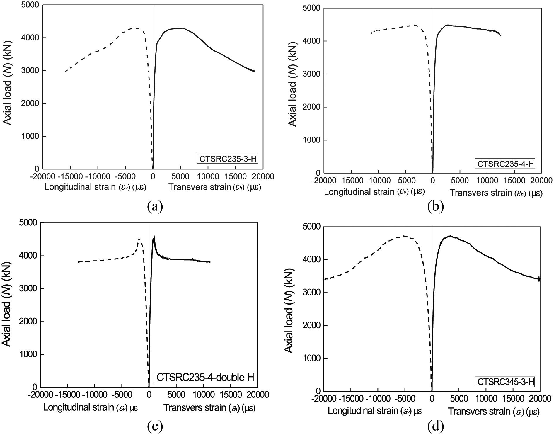
Load–tube strain responses of CTSRC columns: (a) CTSRC235-3-H, (b) CTSRC235-4-H, (c) CTSRC235-4-double H, and (d) CTSRC345-3-H.
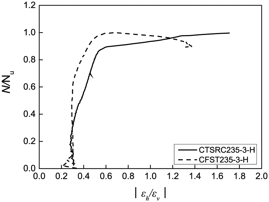
Normalization curve about |εh/εv| of CTSRC columns.
Elastic–plastic analysis on steel tube of CTSRC columns
Based on the strains obtained in Figure 5, the stresses of the tube can be calculated (Zhang et al., 2005).
In the elastic range of the tube, the Hooke’s law is applied

where σh and σv are the transverse stress and longitudinal stress, respectively; εh and εv are the transverse strain and longitudinal strain, respectively, measured by the gauges bonded at the mid-height of the specimens. µs is the Poisson’s ratio of steel in the elastic phase, which equals to 0.283 for low-carbon steel. Es is the elastic modulus of the tube.
As for the elastic–plastic range, elastic–plastic incremental theory (Han et al., 2009) is applied. In the plastic range, von Mises yield criterion is used

Here



where Et is the tangent modulus in the elastic–plastic range of the steel tube. σz is the equivalent stress of the steel tube. µsp is the Poisson’s ratio in the elastic–plastic range. ft is the yield strength of the steel tube. fp is the proportional stress of the steel tube, which can be calculated as fp = 0.7ft.
As for the plastic hardening range, the von Mises yield and the Prandtl–Reuss flow rule are adopted to analyze the behavior of the steel
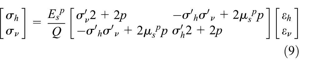






where
The load–tube stress responses are depicted in Figure 7. For all the CTSRC columns, the tube yielded near the peak loading point. For CTSRC235-3-H, horizontal stress was higher than vertical stress while for CTSRC235-4-H and CTSRC235-5-H, horizontal stress was less than vertical stress when the tube yielded. The explanation is that a stronger confinement provided by a column with higher t leads to a better mechanical performance of the columns. The initiation of the lateral expansion of the concrete delayed with the increase in t. Figure 7(b) and (f) illustrates the influence of the tensile strength of the tube. There is no tremendous increase in the horizontal stress of CTSRC345-3-H compared with CTSRC235-3-H. Consequently, the enhancement of confinement effect due to the increase in tube’s tensile strength is fairly limited.
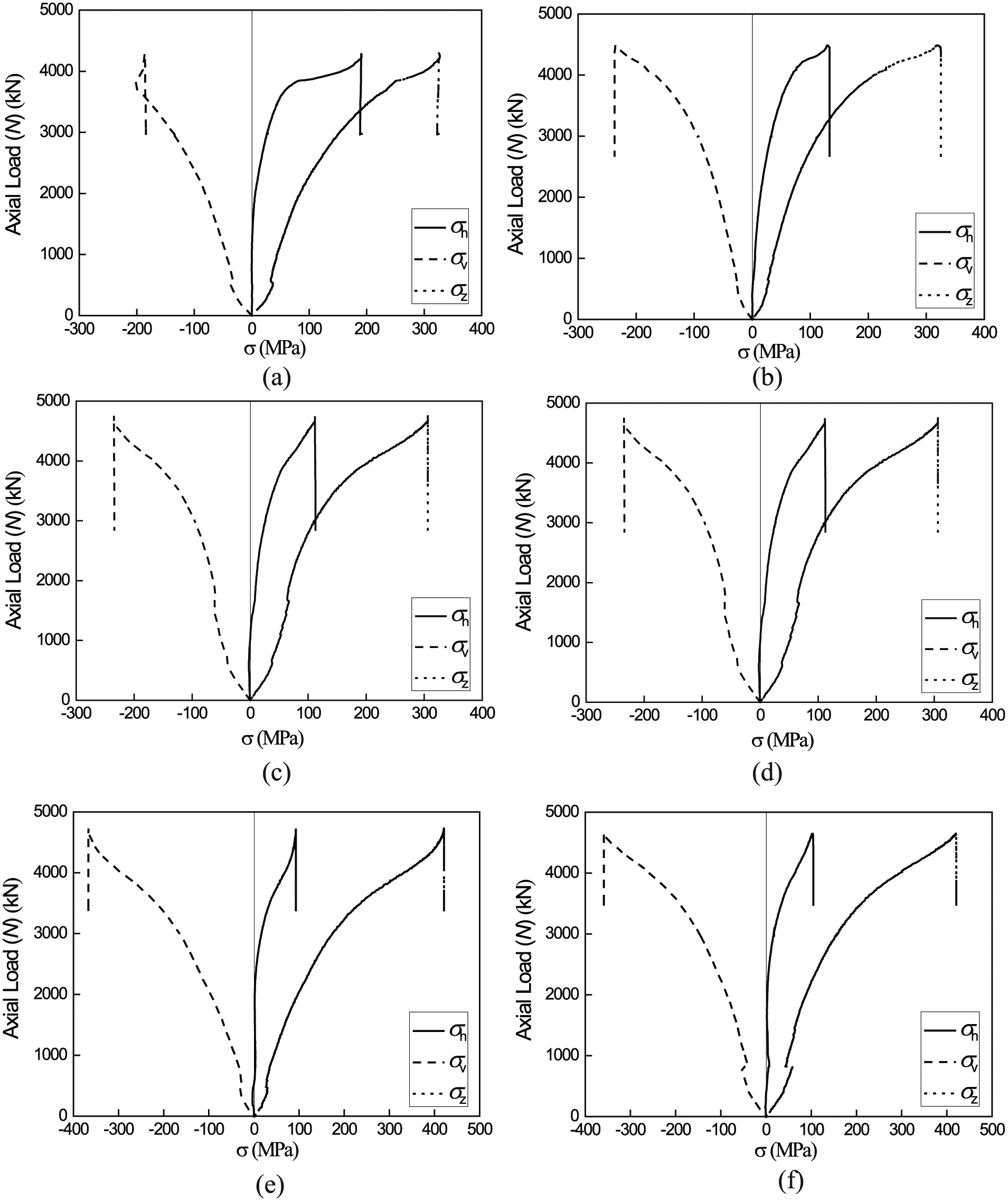
Load–tube stress responses of CTSRC columns: (a) CTSRC235-3-H, (b) CTSRC235-4-H, (c) CTSRC235-5-H, (d) CTSRC235-3-O, (e) CTSRC345-3-H, and (f) CTSRC345-4-H.
Experimental results and discussions of STSRC columns
Failure modes of STSRC columns
Figure 8 demonstrates the failure modes of STSRC columns. Similar to CTSRC columns, all the STSRC columns had shear failure in the concrete. However, the brittleness of ultra-high-strength concrete played a more significant role for STSRC columns, and the failure process is different from CTSRC columns. Right after the specimen reached its peak load, the tube yielded. They almost happened simultaneously. In the meantime, there was an energy release process with an explosive sound. This phenomenon can imply an inferior confinement effect of the square tube compared to the circular tube. In other words, the square tube cannot provide enough confinement in prevention of the brittle failure of ultra-high strength.
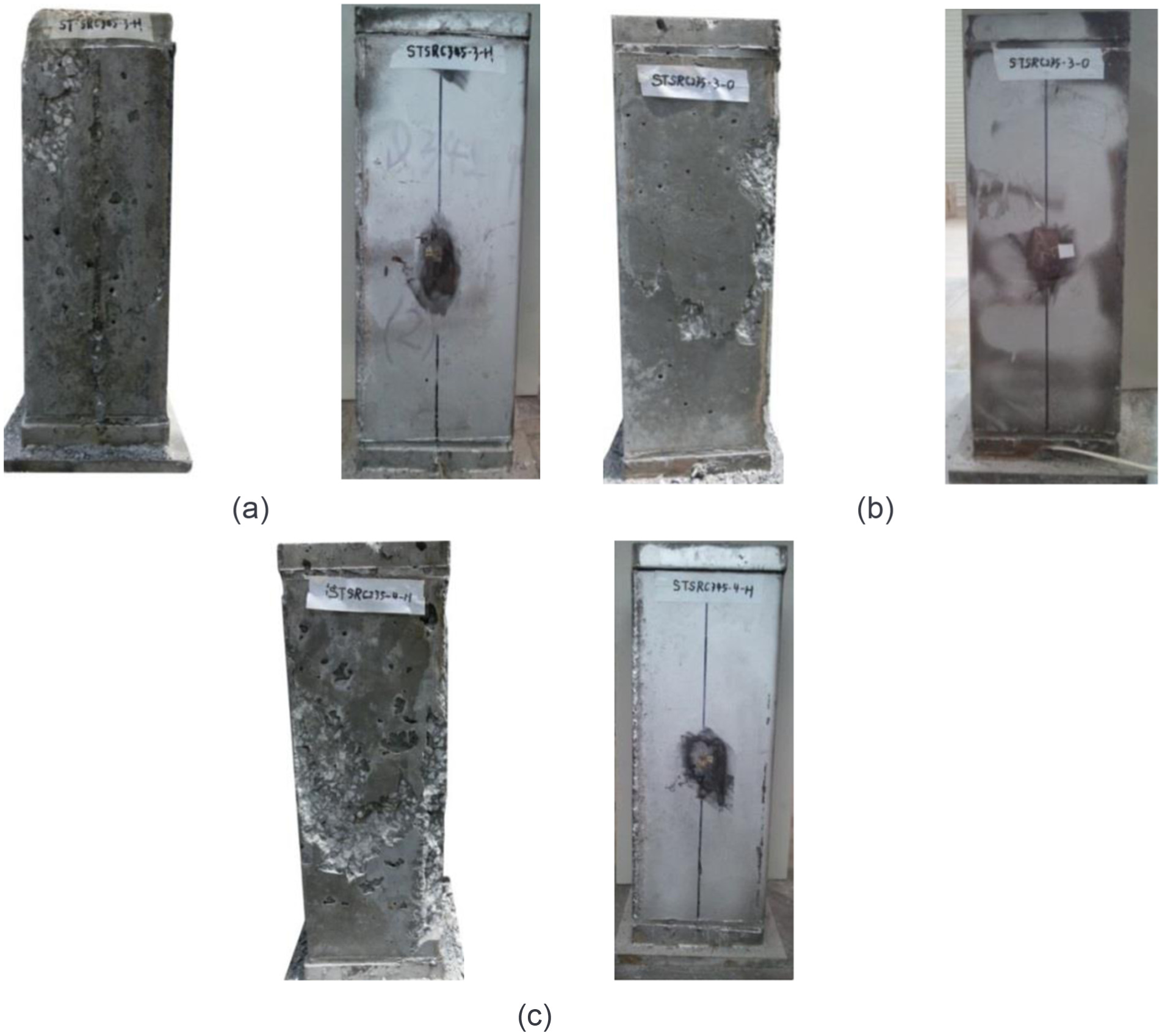
Failure modes of STSRC columns: (a) STSRC345-3-H, (b) STSRC235-3-O, and (c) STSRC345-4-H.
Load–axial deformation responses of STSRC columns
The load–axial displacement curves (N–Δ) are shown in Figure 9, where Δ is the average displacement measured by the LVDTs. The maximum loads (Nue) obtained in the test are summarized in Table 2. Compared with SFST column (square concrete-filled steel tube), the load capacity of STSRC columns was improved apparently. The curves of square specimens showed the same trend and changes with circular specimens in Figure 9(a) and (b). Figure 9(c) demonstrates the N–Δ curves of the columns with different shapes of steel, and the shaped steel ratios are equal. The axial load capacities of STSRC235-3-double H and STSRC235-3-O improved 26.09% and 18.47%, respectively, compared to SFST235-3-H. This tells that the shape of steel section does affect the performance of the columns. STSRC235-3-O and STSRC-3-double H* showed nearly the same strength and stiffness, and STSRC235-3-H showed the worst. From Figure 9(d), it can be noted that the stiffness of the columns was remarkably improved due to the increase in tensile strength of the tube which was different with circular specimens. For STSRC235-4-H and STSRC345-4-H, their peak loading is almost equal; therefore, the tensile strength of the tube had limited influence on the strength of the column like circular specimens.
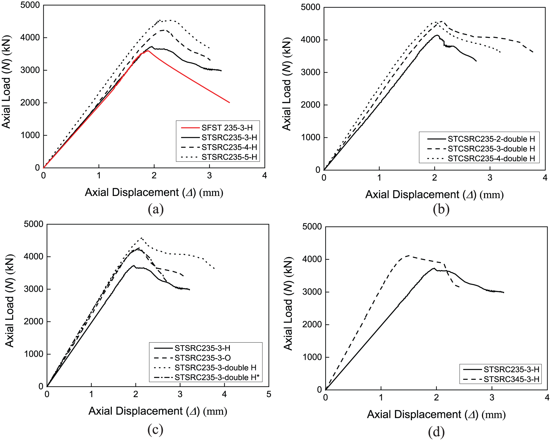
Load–axial displacement curves of STSRC columns: (a) effect of thickness of steel tube (H), (b) effect of thickness of steel tube (double H), (c) effect of thickness of shape of inner steel, and (d) effect of tube tensile strength (t = 3 mm).
As for ductility of STSRC columns, the efficiency of the confined steel tube can be verified that the DI values of whole STSRC columns were superior to SFST columnsas shown in Table 4. It has a semblable variation tendency with N–Δ curves of CTSRC columns. The O-shape (STCRC235-3-O) showed the best behavior in load capacity and ductility synthetically. It is induced that the larger the area of the concrete that could be constrained by the steel shape, the better the performance it could provide. As a whole, however, STSRC columns behaved a little weak compared with CTSRC columns.
SEI and ductility evaluation of square short columns.
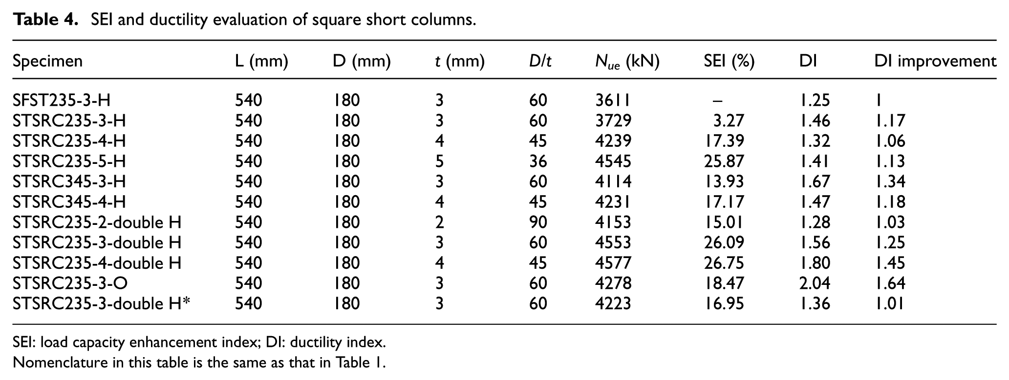
SEI: load capacity enhancement index; DI: ductility index.
Nomenclature in this table is the same as that in Table 1.
Normalization curve about |εh/εv| of STSRC columns
The horizontal strains (εh) and four vertical strains (εv) were obtained from gauges bonded at the mid-height of the specimens same as CTSRC columns. As shown in Figure 10, the comparison between STSRC and SFST of the normalization curve about |εh/εv| can be concluded in the same manner as CTSRC and CFST. The value of |εh/εv| remained unchanged instead of increasing suddenly when the load is in the range of 0.4Nu to Nu. It could be noted that the STSRC columns provided inferior confinement effect but still superior to SFST.
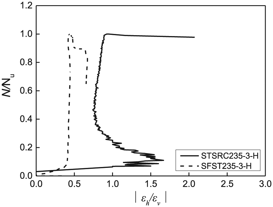
Normalization curve about |εh/εv| of STSRC columns.
Elastic–plastic analysis on steel tube of STSRC columns
The stresses are calculated according to the method discussed in section “Elastic–plastic analysis on steel tube of CTSRC columns,” and the load–tube stress responses are depicted in Figure 11. For all the STSRC columns, the tube yielded after the peak loading point. When the specimen reached its peak loading point, the broken in concrete happened suddenly which cause a rapid-release of bearing capacity. For all the STSRC235-3-H, STSRC235-4-H, and STSRC235-5-H columns, horizontal stress was less than vertical stress when the tube yielded. That is because the confinement of the square tube is not as effective as the circular tube, and the confinement that the square tube could provide is limited. Figure 11(b) and (f) illustrates the influence of the tensile strength of the tube. The horizontal stress of STSRC345-3-H was nearly the same as that of STSRC235-3-H. Consequently, like CTSRC columns, the enhancement of confinement effect due to the increase in tube’s tensile strength is fairly limited.
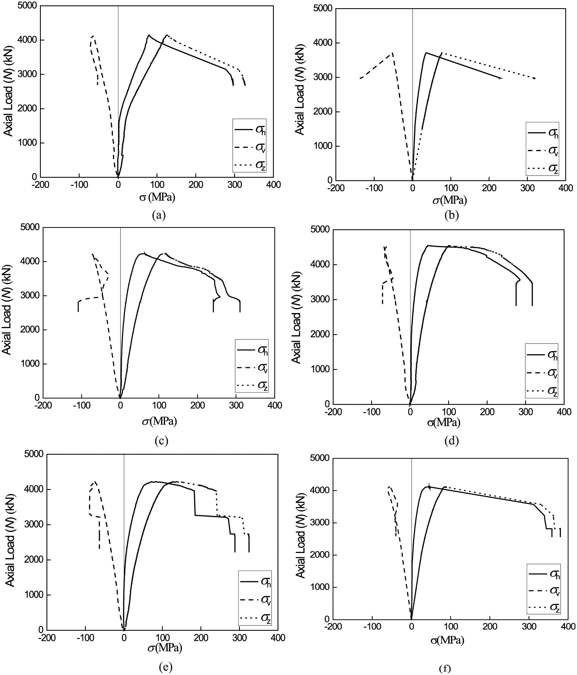
Load–tube stress responses of STSRC columns: (a) STSRC235-2-X, (b) STSRC235-3-H, (c) STSRC235-4-H, (d) STSRC235-5-H, (e) STSRC235-3-X*, and (f) STSRC345-3-H.
Ultimate load-carrying capacity of tubed SRC short columns
Ultimate load capacity of CTSRC short columns under axial loading
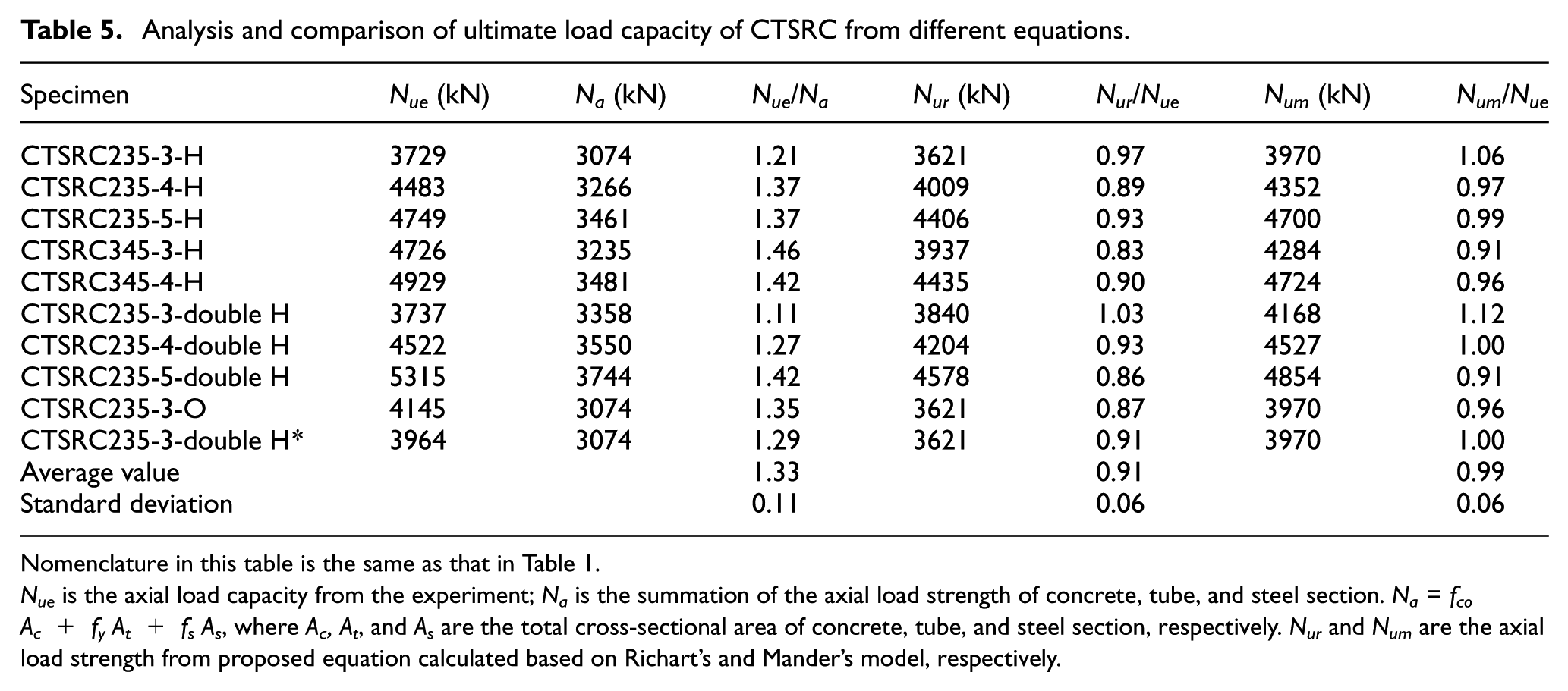
The calculation method is discussed for CTSRC short columns under axial loading. Three methods will be presented and the predicted values will be compared with this study’s test results (Table 5).
Analysis and comparison of ultimate load capacity of CTSRC from different equations.
Nomenclature in this table is the same as that in Table 1.
Nue is the axial load capacity from the experiment; Na is the summation of the axial load strength of concrete, tube, and steel section. Na = fco Ac + fy At + fs As, where Ac, At, and As are the total cross-sectional area of concrete, tube, and steel section, respectively. Nur and Num are the axial load strength from proposed equation calculated based on Richart’s and Mander’s model, respectively.
The ultimate load capacity can be calculated through equation (16) which simply aggregates load bearing of each section in this composite structure

where Ac, At, and As are the total cross-sectional area of the concrete, tube, and steel section, respectively. fco, fy, and fs are the compression strength of the unconfined concrete, the yield strength of the steel tube, and steel section respectively.
Zhou and Liu (2010) proposed a design method to calculate the axial load strength of tubed SRC columns. In this method, the longitudinal stress of steel tube was not considered in the calculation of axial strength. It is because of the two small grooves cut on the tube near the edges of each specimen in guarantee that the tube was not under direct compression during the test. The equation can be illustrated as

where Ac and As are the cross-sectional area of the concrete and the cross-sectional area of the steel section, respectively. fcc and fs are the compression strength of the confined concrete and the yield strength of the steel section, respectively.
Richart et al. (1928) proposed an equation of the compression strength of the confined concrete

in which fco is the compression strength of the unconfined concrete. fr,c is the effective confining stress of the circular tube acting on the concrete that can be calculated as follows

Another widely accepted calculation of the compression strength of the confined concrete was proposed by Mander et al. (1988)

Based on the two methods mentioned above, the test results of the axial load capacity and predictions are plotted in Table 5. The summation of each material’s strength in the cross section is also presented by Na. From the results of Nue/Na, it is obvious that this kind of composite structure does combine those sections in an efficient way that produces something greater than the sum of the parts with the load capacity enhancement of 33% approximately. It is induced that the confinement of the steel tube is more excellent when the steel tube is not subjected to the axial compression load directly. The local buckling of the tube can be delayed which improves the ductility of the high-strength concrete. The calculation results based on Mander’s model showed a great agreement with the test results of an average value of about 0.99. And the results based on Richart’s model provided more conservative results with an average value of about 0.91. The main reason for this result is the Richart’s model does not account for the influence of concrete strength on the enhancement of confined concrete strength; however, the Mander’s model is more reasonable accounting for the influence of both confining pressure and concrete strength.
Ultimate load capacity of STSRC short columns under axial loading
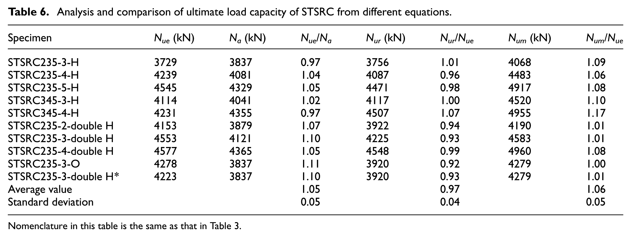
The design method proposed for CTSRC columns can be applied to STSRC columns as well. The coefficient fr,c should be replaced by fr,s as the confinement effects of the circular and square tubes are different

where σh,s is the transverse stress of the square tube at the peak load point, and
Table 6 indicates the test results of the axial load capacity and predictions for STSRC columns. Compared with CTSRC columns, the axial load capacity of STSRC columns was slightly improved due to the poor confinement effect of the square tube. From the results of Nue/Na shown in Table 6, it is obvious that this kind of composite structure had no significant effect on ultimate capacity of STSRC. The calculation results based on Richart’s model and Mander’s model do not consist well with the test results. The load-carrying mechanism of the square columns is more complicated than the circular columns such as the effects of stress concentration in corners. The ultimate load capacity prediction needs to be investigated in the future.
Analysis and comparison of ultimate load capacity of STSRC from different equations.
Nomenclature in this table is the same as that in Table 3.
Summary and conclusion
This article provides experimental and analytical results of tube-confined steel-reinforced ultra-high-strength concrete short columns subjected to axial compression. A total of 22 columns (11 circular columns and 11 square columns) were tested to failure under compression. Their failure modes, compressive load capacity, ductility, and the influence of parameters were compared, including the shape of the tubes (circular and square), the shape of steel (H, double H and O), the thickness t, and tube tensile strength (Q235 and Q345). The following are the conclusions obtained from the experimental research:
The CTSRC column and STSRC column has efficient influence compared to CFST column and SFST column including its excellent bearing capacity and ductility and improves the brittleness of ultra-high-strength concrete more validly.
The increase in thickness can effectively improve the strength of the SRC columns when the length-to-diameter/width ratio of each column is 3. However, the enhancement of confinement effect due to the increase in the tube strength is limited when the thickness of the steel tube exceeds 3 mm.
The shape of inner steel section does affect the behavior of the columns. O-shape exhibited the worst mechanical performance than others with the same thickness of the steel tube and equal shape steel ratios.
For SRC columns, the confinement effect of the circular tube is greatly superior to that of the square tube, for the reason that the circular tube can efficaciously prevent the ultra-high-strength concrete from brittle failure; however, the square tube cannot in consequence of the stress-focusing effect.
The combination of the different portions in a composite ways has a greater performance in load capacity. The load capacity can be increased evidently compared with the simple sum of the strength of high-strength concrete, steel tube, and steel section.
For CTSRC strut columns, Richart’s equation is recommended to calculate the load-bearing capacity. It should be noted that the shape of the steel is an important parameter in the calculation of the load-bearing capacity. The bearing capacity formula taking into account the parameter of the shape of the steel should be studied in the future.
It is notable that the magnitude of the efficiency depends significantly on the geometry of the specimen configuration and material characteristics. This aspect does not relate directly to the confining effect but influences the assessment of the results.
Footnotes
Appendix 1
Declaration of Conflicting Interests
The author(s) declared no potential conflicts of interest with respect to the research, authorship, and/or publication of this article.
Funding
The author(s) disclosed receipt of the following financial support for the research, authorship, and/or publication of this article: This research was financially supported by National Science Foundation of China (project no. 51178078), which is gratefully acknowledged.