
Abstract
Engineered cementitious composite is an advanced composite material with strain-hardening and multiple cracking behavior. Substituting conventional concrete with engineered cementitious composite can significantly improve the seismic performance of reinforced concrete structures. This article presents the seismic behavior of a precast engineered cementitious composite/reinforced concrete composite frame and a precast reinforced concrete frame. In the precast engineered cementitious composite/reinforced concrete composite frame, engineered cementitious composite is used to replace concrete in the beam-to-column joints and the bottom columns. The shaking table test results on the two scaled frames are presented. The frame failure characteristics and dynamic properties, including the fundamental frequency, story displacement, inter-story drift, and story acceleration, are comprehensively studied. The test results indicate that the connection method adopted in the tested frames is applicable and reliable. Both of the frames have good seismic performance and can withstand earthquakes at the design seismic intensity. Using engineered cementitious composite in precast frames can greatly reduce damage. The precast engineered cementitious composite/reinforced concrete composite frame has better deformation capacity, better energy dissipation ability, and slower stiffness deterioration than the precast reinforced concrete frame.
Keywords
Introduction
In recent years, precast reinforced concrete (RC) structures have received increasing attention. Precast RC structures have the advantage of rapid and economical construction, offer high allowances for quality controls, and require less on-site labor (Brunesi et al., 2015). However, some researchers have indicated that precast RC structures suffer far more serious damage than cast-in-place RC structures. Precast RC structures exhibit severe damage in the connection areas but only slight damage in the precast members; therefore, connections are the critical areas of RC precast structures (Ghosh and Cleland, 2012; Khoo et al., 2006). Recent earthquakes in New Zealand (4 September 2010, Mw = 7.0 and 22 February 2011, Mw = 6.1) and Italy (20 and 29 May 2012, Mw = 5.9) confirmed these findings and presented the main failure modes experienced by precast RC structures, particularly for precast RC frames (Belleri et al., 2015; Liberatore et al., 2013; Smyrou et al., 2011).
In the past decades, extensive research has been undertaken to test different types of connections since the seismic response of precast RC frames greatly depends on the behavior of the connections. Prestressing tendons and U-shaped steel bars are preferred for rigid beam-to-column connections. These properly designed connections have been shown to be suitable for seismically active regions in terms of strength and energy dissipation (Alcocer et al., 2002; Ertas et al., 2006; Parastesh et al., 2014; Priestley and Macrae, 1996; Varney et al., 2011). Pinned beam–column connections are also traditionally used in precast RC frames. Some experiments demonstrated that pinned connections were a viable solution for improving the response of precast RC frames subjected to seismic loads and could accommodate large rotations without significant loss of strength (Belleri and Riva, 2012; Bournas et al., 2013; Psycharis and Mouzakis, 2012a, 2012b).
Beam-to-column joint is a typical connection in a precast or cast-in-place RC frame. However, beam-to-column joint is designed to sustain vertical loads and horizontal loads simultaneously, leading to complicated stress in the joint zone. It undoubtedly weakens the integrity and seismic performance of precast concrete structure. Therefore, it may be more suitable to locate the connections in regions with minimum stress instead of at beam-to-column joints. In this article, a new type of connection system that includes a beam-to-beam connection and a column-to-column connection is developed for precast concrete frames in seismic regions. These connections are located near the inflection point of structural member, where the minimum stress occurs. Compared with conventional beam-to-column connections, the proposed connections are expected to improve the integrity of precast structures and eliminate premature connections failure.
In addition to inadequate connections, the lack of ductility and energy dissipation capacity limits the application of precast RC frames in seismic regions. To improve the seismic performance of precast RC frames, this article proposes replacing concrete with a high-performance fiber-reinforced cementitious composite called engineered cementitious composite (ECC) at the beam-to-column joints and at the bottom columns of precast RC frames. ECC is a type of advanced composite material with strain-hardening and multiple cracking behavior (Li and Wu, 1992; Naaman and Reinhardt, 1996). Experimental results of ECC and ECC/RC composite members and frames have indicated that ECC can improve the structural integrity, ductility, and energy dissipation ability at various stages; furthermore, ECC can partially replace the shear reinforcement in the joints and the columns, decreasing the amount of stirrups required (Fischer and Li, 2002, 2003; Li and Wang, 2002; Yuan et al., 2013). Considering the high cost of ECC, applying ECC in entire precast frames is not economical. The application of ECC in critical regions of the structure, such as beam-to-column joints and the bottom of columns, can simultaneously reduce the construction cost and improve seismic performance. Hence, a precast ECC/RC composite frame is expected to have superior seismic performance than a precast RC frame.
Nowadays, the shaking table test is the most widely adopted method to evaluate the seismic performance of structures. Dolce et al. (2005) compared the seismic performance of RC frames with and without passive control systems. Li et al. (2006) carried out a shaking table test of a 1:20 scale high-rise building with a transfer plate system. Lu et al. (2007) fabricated a 1:50 scaled model of Shanghai World Financial Center Tower and tested on shaking table. The data obtained from these shaking table tests could accurately assess the structural damage. This article presents the seismic response of a precast ECC/RC composite frame and a precast RC frame with shaking table tests. The seismic performances of the precast frames are evaluated based on the experimentally recorded dynamic responses, including fundamental frequencies, story displacements, inter-story drifts, and story accelerations.
Experimental program
Model preparation
The experimental model was scaled down by a factor of 3 (i.e. dimension scale factor SL = 1/3) from a typical building structure to fully satisfy the dimensions and the load capacity of the shaking table facility. The prototype structure is a four-story, single-bay, symmetrical frame that is square in plan. The design of the full-scale prototype was established according to the China Code for the seismic design of buildings (China Ministry of Construction, 2010). It requires the precast concrete structures to be regarded as the cast-in-place concrete structures in the seismic design. But some unique principles should be obeyed. For instance, the connection areas for precast members are recommended in the places with smaller stresses. The interface between precast members should be roughed. The post-poured concrete should have higher strength than the concrete used in precast members. Longitudinal bars in columns cannot be disconnected in the joint zones. Reliable connection method should be used to connect load-bearing bars in columns and beams, such as mechanical connection, weld, etc. The following main design parameters were selected: type-one seismic design group, type-two site condition, seven-degree seismic fortification intensity, and 0.10 g basic design acceleration. The imposed load (variable load) is 2.0 kN/m2 based on the load code for the design of building structures (China Ministry of Construction, 2012), and 0.4 kN/m2 is considered as the finishes and screeding load.
Generally, amplified accelerations are demanded to prevent the measurements from being distorted by the noise wave (Lu et al., 2007); therefore, the horizontal acceleration for the tested models was magnified by 2 times (Sa = 2). Other similitude scale factors of the tested models were calculated according to similarity laws and are shown in Table 1.
Similitude scale factors of the tested models.

Two models were tested to study the seismic behavior of precast frames: a precast RC frame and a precast ECC/RC composite frame. Figures 1 and 2 show the detailed dimensions of the models. For the ECC/RC composite frame, the ECC material was used in the beam-to-column joints and the bottom columns. The ECC material was also used in the connections of the foundation beams to strengthen the interface between the column and foundation beam, as shown in Figure 1.
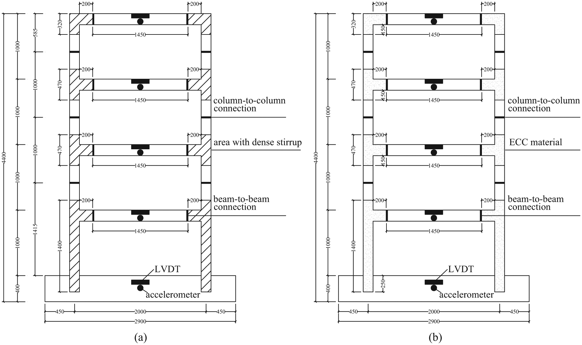
Detailed dimensions of the tested models in elevation (a) RC frame and (b) ECC/RC composite frame.

Detailed dimensions of the tested models in plan (a) RC frame and (b) ECC/RC composite frame.
All columns have an identical cross section of 150 × 150 mm, and all beams have an identical cross section of 85 × 170 mm. Four large foundation beams with a cross section of 300 × 400 mm were used to provide fixed constraints for the columns at the base. The details of steel reinforcement configuration for the beams, columns, and base beams are shown in Figure 3. For the precast ECC/RC composite frame, 6-mm-diameter bars were used as the shear reinforcement in all the beams and columns with a spacing of 150 mm. For the precast RC frame, the 6-mm-diameter shear reinforcement with a spacing of 75 mm was used in the beam-to-column joints and the bottom columns, and a spacing of 150 mm for the shear reinforcement was used in other areas. The areas with the increased stirrup ratio in the precast RC frame are shown in Figure 1. The floors have a thickness of 50 mm. 6-mm-diameter steel bars were used as bi-directional reinforcement for the floor with a spacing of 80 mm. Mass-similitude scaling required a mass system with a weight of 17.47 kN for the roof and 27.2 kN for each of the other stories. The weight of each model was approximately 170 kN.

Reinforcement details of the tested models: (a) beam (b) column, and (c) base beam.
Proposed connection
A new connection system, including beam-to-beam connections and column-to-column connections, was developed in this article. The column-to-column connection was designed in the middle of the column, while the beam-to-beam connection was designed 200 mm away from the column edge, as shown in Figures 1 and 2. The connections were located near the inflection points as calculated from the internal force analysis for the frame structure. The bottom columns were integrally prefabricated to improve the seismic behavior of the first story and to avoid the formation of a weak story.
Figure 4 shows the details of the connections between the precast members. The columns were prefabricated along with the beam-to-column joints, and four grout sleeves were pre-embedded in the bottom of the precast columns for connecting corresponding longitudinal bar of the lower columns. The connection faces of the columns were roughened to increase the connection strength before a thin layer of high-strength mortar was placed between the two connecting columns. The beam-to-beam connections were similar to those of the columns. However, the beams were partly prefabricated with a height of 140 mm. The remaining parts were constructed with concrete floors to increase the structural integrity.
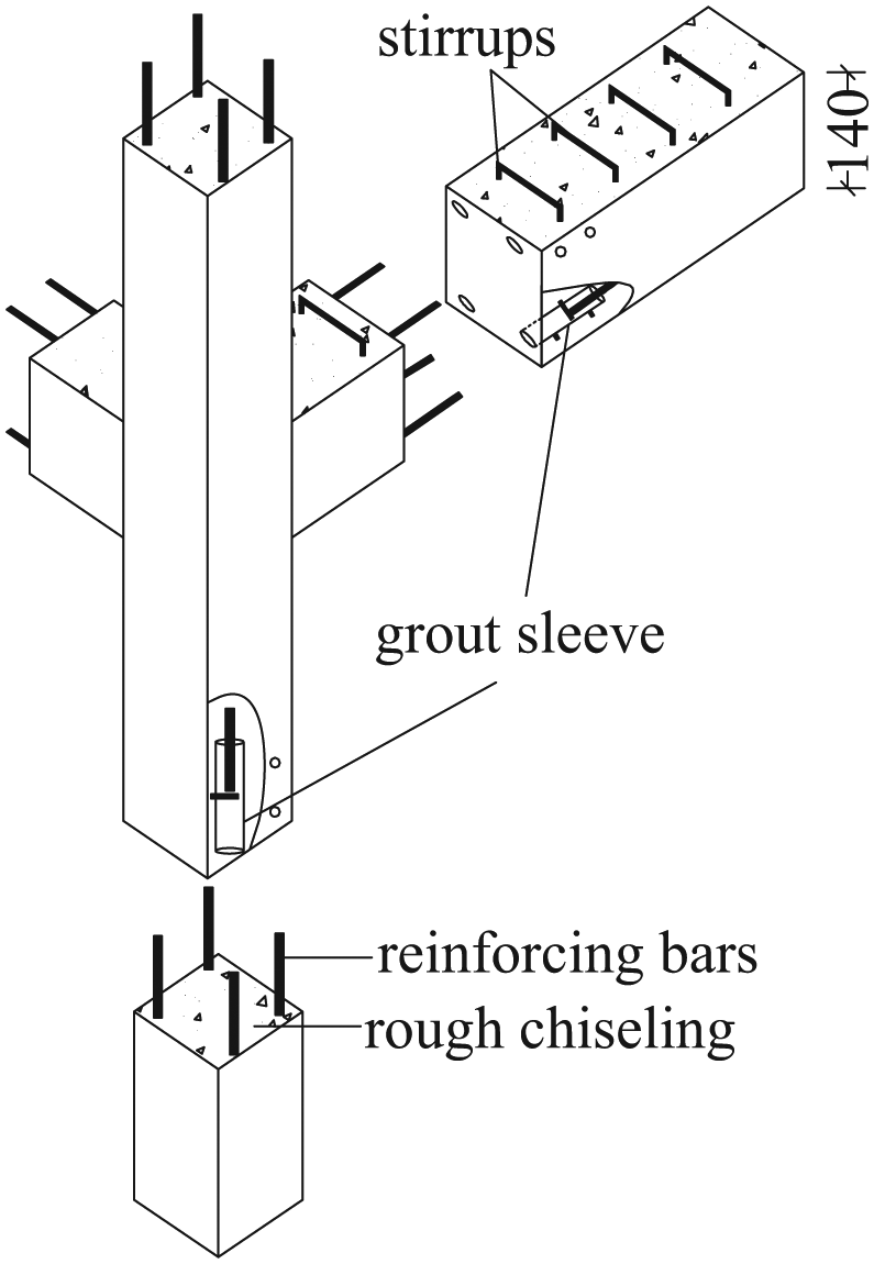
Details of the precast connection.
In the installation process, the longitudinal bars of the precast columns were first inserted into the grout sleeves, and then the horizontal bars from the beam joints were also inserted into the precast beams. High-strength grout was injected into the grout sleeves to connect the precast members, and the entire structure was completed after pouring the concrete floors. The connection methods in this test are complied with the seismic design requirement.
Material properties
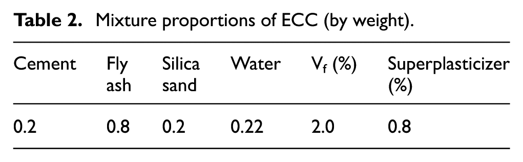
The constituents of ECC include Portland cement, fine silica sand, fly ash, polyvinyl acetate (PVA) fibers, super-plasticizer, and water. Ready-mixed concrete (concrete grade: C30) was used in the specimens. Mixture proportion of ECC and concrete is shown in Tables 2 and 3. Uniaxial tension tests were conducted to evaluate the ductile behavior of ECC. The specimens with dimensions of 350 × 5 × 15 mm were prepared and tested in uniaxial tension. Figure 5 shows the tensile stress–strain relationship of ECC, which indicates that the tensile strength of ECC can reach 5 MPa and the ultimate tensile strain approaches 4%.
Mixture proportions of ECC (by weight).
Mixture proportions of concrete (by weight).
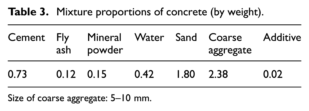
Size of coarse aggregate: 5–10 mm.

Tensile stress–strain relationship of ECC.
A number of cubic concrete and ECC specimens with dimensions of 150 × 150 × 150 mm were prepared and tested for obtaining the compressive strength. The compressive strengths of concrete and ECC are 33.73 and 35.53 MPa, respectively. The specimens with dimensions of 40 × 40 × 120 mm were prepared with grouting material used in grout sleeves and tested for compressive strength. The compressive strength of the grouting material is 81.2 MPa. Table 4 summarizes the material properties of the steel reinforcement obtained from direct tension tests. Reinforcing bars with a diameter of 6 mm (#6 bars) have a much lower yield and ultimate strength than other reinforcing bars because #8 and #12 bars are hot-rolled steel bars, while #6 bars are made from mild steel wire.
Material properties of steel reinforcement.
Test setup
In the experiments, shaking table was loaded by a horizontal hydraulic actuator, which was fixed on the reaction wall. Each scaled frame model was fixed on the shaking table with 28 vertical steel anchors.
A number of sensors were installed to record the overall and local seismic responses of the models during the testing. Five linear variation displacement transducers (LVDT) were used to measure the horizontal displacement variation of each story. An accelerometer was installed on the beam beside each LVDT, measuring the absolute horizontal acceleration. The distributions of the LVDTs and accelerometers for the scaled frame models are shown in Figure 1.
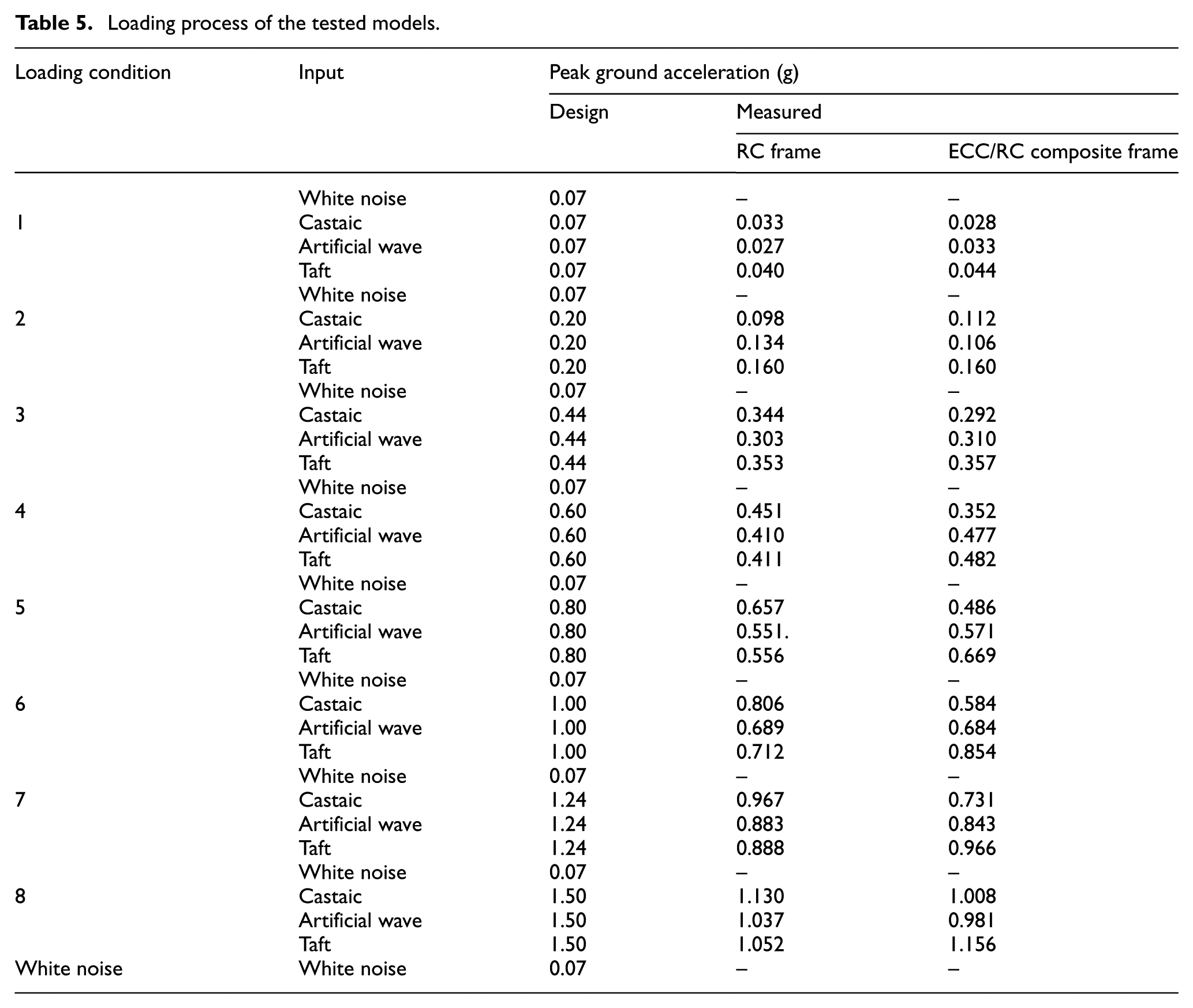
Loading process
Each model was subjected to an alternating series of seismic tests and random tests. The seismic tests evaluated the structural response to seismic motion with increasing intensity or peak ground acceleration (PGA) and included three types of seismic motion: Castaic wave, Taft wave, and artificial wave. The Castaic wave and Taft wave cases are really recorded motions, while the artificial wave is artificially generated ground motion. The predominant period of the recorded Castaic wave, Taft wave, and artificial wave is 0.32, 0.34, and 0.37 s respectively, which is very close to the characteristic period of the site 0.35 s, as the China Code for the Seismic Design of Buildings (China Ministry of Construction, 2010) requires. And the relative error between the average response spectrum of inputted seismic motions and the design response spectrum should be less than 20%. Figure 6 shows the normalized inputted acceleration profiles for each seismic motion. The average response spectrum of the seismic motions was compatible with the design response spectrum in the majority of the periods as shown in Figure 7, indicating that the selected seismic motions were suitable for the site conditions of the prototype structure. The random tests were conducted to assess the damage suffered by the structure during the previous seismic event by evaluating the fundamental frequency of vibration. The input motion for the random tests was white noise with an acceleration amplitude of 0.07 g; thus, the models had linear elastic deformations in these periods (Lu et al., 2007).
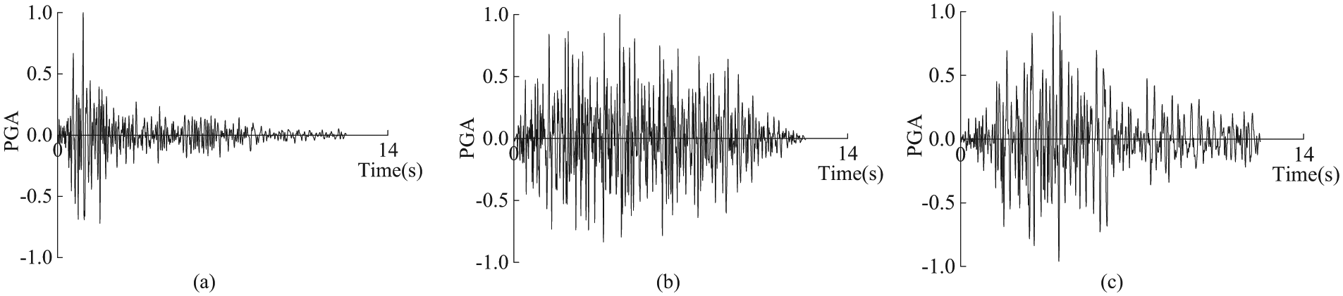
Normalized input waves for the shaking table test: (a) Castaic wave (b) artificial wave, and (c) Taft wave.

5% damped response spectra of the seismic motion.
The full-scale prototype was designed to experience seismic motions from 0.035 to 0.75 g PGA. In the test, the amplitude of the acceleration profile was scaled up by a factor of 2 and sped up by a factor of 0.408 for consistency with the model. Thus, the peak table acceleration progressively increased from 0.07 to 1.5 g for the eight loading conditions in the tests. Table 5 shows the details of the loading process. The designed peak table accelerations are different from the measured values because of the inevitable errors generated from the control system of the shaking table.
Loading process of the tested models.
Experimental results and discussion
Crack patterns
After each loading condition, the crack patterns were recorded to analyze the damage progress. Figure 8 shows the final crack patterns of the two models. For the precast RC frame, no visible macro-cracks were found in the first two loading conditions, indicating that the structural model was still in the elastic stage. After the third loading condition, some visible cracks occurred in the beam-to-beam connections along the direction of vibration of the first and second stories because of the low bonding strength between the grout and the concrete. In addition, some flexural cracks appeared at these beam ends. At the fourth loading condition, existing cracks in the connection areas propagated toward the center of the beam. Some tiny cracks appeared at the beam-to-beam connections in the third and fourth stories. Meanwhile, some flexural-shear cracks occurred in the beam–column joints with 45° angle, and horizontal cracks were observed in the bottom of columns in the first story. In the subsequent two loading conditions (i.e. fifth and sixth), more flexural-shear cracks occurred in the beam–column joint zones, and more flexural cracks occurred in the columns of the first story. The maximum width of the cracks at the beam ends of the first and second stories was approaching to 3 mm. After the seventh loading condition, the flexural-shear diagonal cracks in the beam–column joints continued to propagate. Concrete crushing and spalling were observed at four beam ends. Two beam ends were in the second story, and the other two were in the first and fourth stories, respectively, indicating the formation of plastic hinges. In the final loading condition, the frame vibrated with a large amplitude and the crack widths significantly increased.
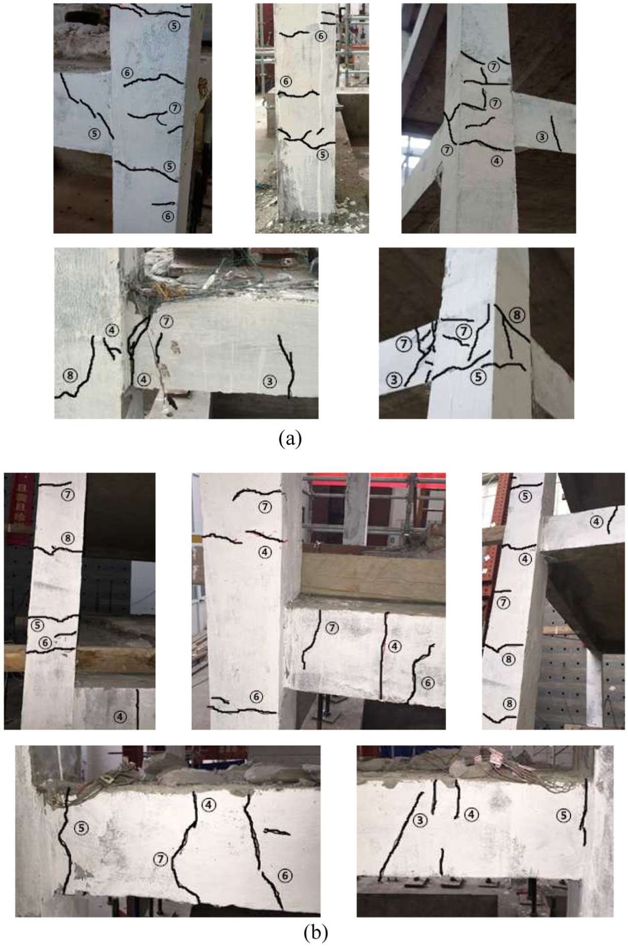
Crack patterns of the tested models: (a) RC frame and (b) ECC/RC composite frame.
For a precast ECC/RC composite frame, the propagation of cracks was approximately similar to that of the precast RC frame in the first three loading conditions. At the fourth loading condition, more cracks occurred in the beam-to-beam connections. Moreover, tiny horizontal cracks appeared at the interface between concrete and ECC of the columns due to the low bonding strength between the different matrix materials. After the fifth loading condition, the quantity of cracks in the columns increased, especially in the first and second stories. However, very few shear cracks were observed in the beam–column joints, which differ from the RC frame, which mainly presented flexural-shear diagonal cracks in the beam–column joints and fewer cracks in the columns. In the next two loading condition, more horizontal cracks appeared in the columns. At the beam ends, the localized cracks extended to the bottom of the beam, and the crack width became much larger. After the eighth loading process, a major flexural crack was formed at the base of the beam. No spalling of concrete or ECC occurred in this frame.
Cracks were observed at the column-to-column connections as well as beam-to-beam connections. However, these cracks had very limited extension and development during the whole loading process. Some other methods for increasing the interface roughness are useful to decrease the cracks in the connection areas or delay their occurrence. Sandblasting and high pressure water-jet method can be used to increase the roughness instead of artificial roughing used in this test. In addition, increasing the compressive strength of concrete and ECC is also an effective way to improve the bonding strength between the interface.
Natural frequency
The variation in the natural frequency of a structure can be used to assess the damage suffered during an earthquake. In this test, the natural frequency is calculated from the transfer function, which is the ratio of the Fourier transforms of the roof and base accelerations. Figure 9 shows two types of natural frequencies: the fundamental frequency, which is obtained from random tests (white noise), and the equivalent frequency, which is used for comparison and is obtained from Taft wave excitations.
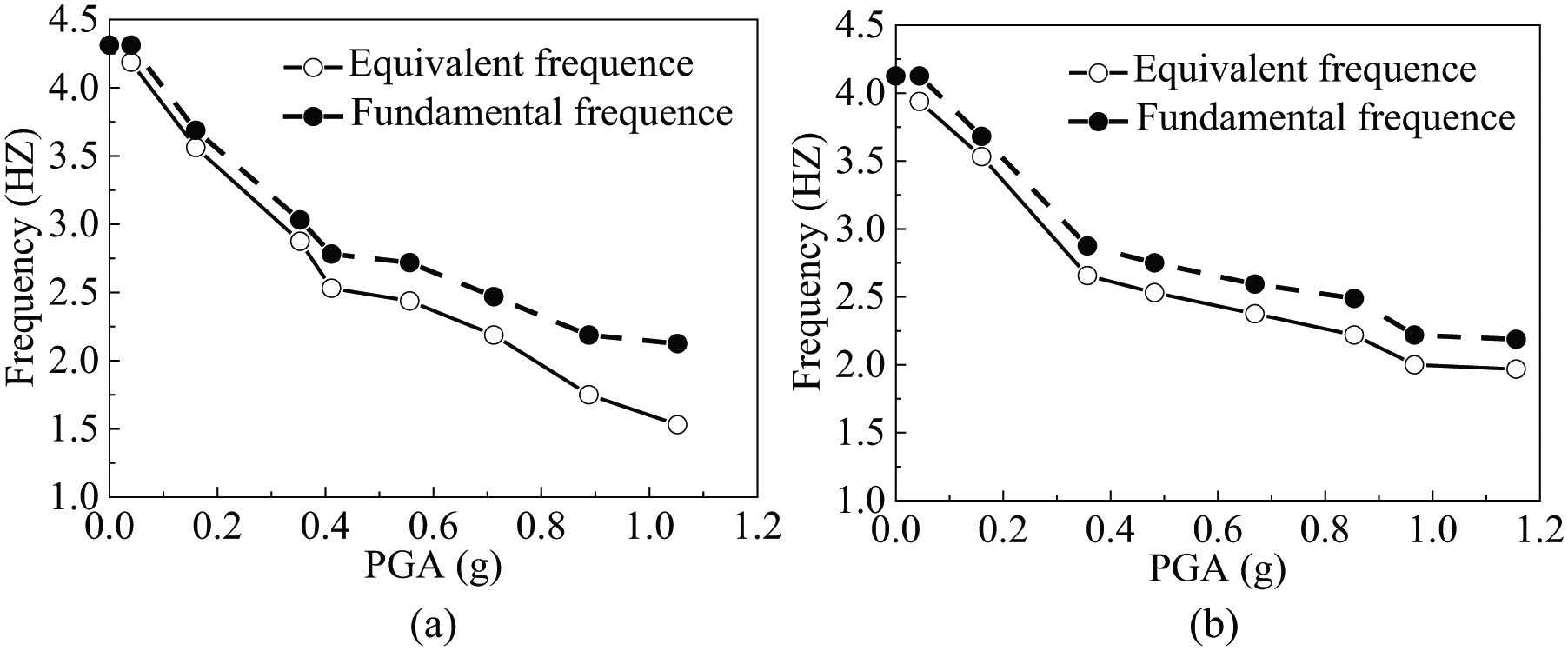
Natural frequency–PGA curves of the tested models: (a) RC frame and (b) ECC/RC composite frame.
For a precast ECC/RC composite frame, the propagation of cracks was approximately similar with increasing PGA, the fundamental and equivalent frequencies of the two frames both decreased, indicating damage development and stiffness degradation. For the precast RC frame, the decreasing fundamental frequency can be approximately divided into two stages. During the first stage, from the first to fourth loading conditions, the fundamental frequency varied from 4.31 to 3.03 Hz. After the fourth loading condition, the fundamental frequency decreased at a slower rate, finally reaching 2.13 Hz. The rapid decrease in the fundamental frequency during the first stage can be attributed to the cracking in the beam-to-beam connection areas and the yielding of the steel reinforcement. The development of the equivalent frequency for the RC frame was similar to that of the fundamental frequency. In the seismic tests, the acceleration amplitude was very large, especially for the later loading conditions, and greatly increased and widened the cracks in the frame. However, in the random tests, the wide cracks re-closed due to the small vibration, and the structural stiffness was larger than that in the seismic tests. Hence, the equivalent frequency was always lower than the fundamental frequency. The difference between them progressively increased with increasing PGA due to continuous propagation of the cracks.
The elastic modulus of ECC is approximately two-thirds that of concrete (Zhou et al., 2015); therefore, the precast ECC/RC composite frame had a slightly lower initial fundamental frequency than the precast RC frame. In the previous three loading conditions, the fundamental frequency decreased rapidly from 4.13 to 2.88 Hz. Then, the frequency degradation continued at a lower and continually decreasing rate. The final fundamental frequency of the ECC/RC composite frame was 2.19 Hz, which was higher than that of the RC frame. This difference indicates that the ECC/RC composite frame had a higher damage resistance and suffered less damage than the RC frame. Moreover, the difference between the fundamental and equivalent frequencies of the ECC/RC composite frame was smaller than that of the RC frame and remained approximately constant with increasing PGA. This phenomenon occurs because during the loading process, multiple small cracks appeared in the ECC/RC composite frame, whereas wide cracks occurred in the RC frame. The closing and opening of cracks in the ECC/RC composite frame were not as obvious as those in the RC frame. In addition, the quantity of cracks in the ECC/RC composite frame increased greatly with increasing vibration intensity, while the crack width of the existing cracks did not increase obviously, resulting in similar differences between the two types of frequencies for different PGAs.
Equivalent damping ratio
The equivalent damping ratio ς is an important indicator for assessing the energy dissipation capacity of structures. This value can be calculated using the half-power bandwidth method, as shown in equation (1)
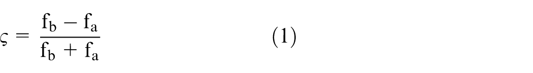
In the equation above, fa and fb are the frequencies where the amplitude is the
Equivalent damping ratio–PGA curves of the tested models.
Absolute displacement response
Comparing the peak values of each recorded displacement or acceleration time history shows that the frames reached their maximum dynamic responses under the Taft wave excitation. It is because the response spectrum of the Taft wave is slightly above those of the Castaic and artificial waves. Therefore, in the following discussion about the dynamic responses, the peak values were obtained from the displacement and acceleration time history recorded under Taft wave excitation.
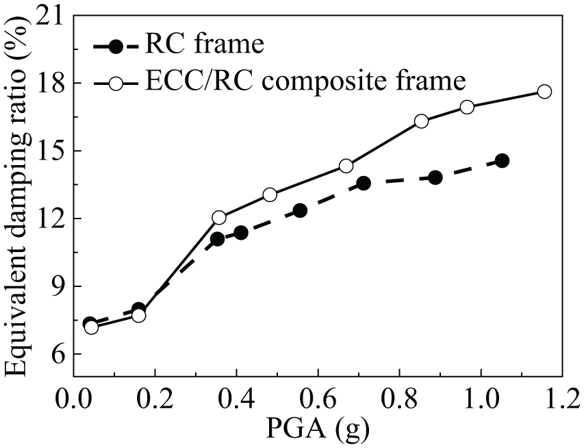
Due to the inevitable errors generated from the control system of the shaking table, the precast ECC/RC composite frame experienced larger seismic motions than the precast RC frame. In order to compare the deformation capacity of the two structures, the absolute displacements of the precast ECC/RC composite frame were scaled down by the PGA ratio of precast ECC/RC composite frame and precast RC frame. Figure 11 shows the distribution of the maximum absolute displacements along the story. It indicates that the absolute displacements of the precast ECC/RC composite frame were larger than those of the precast RC frame at the same PGAs. The application of ECC material in the precast frame structure led to the superior deformation capacity.
Maximum displacement distributions of the tested models: (a) RC frame and (b) ECC/RC composite frame.
Inter-story drift response
Inter-story drift is an important parameter of structural performance. Figure 12 shows the maximum inter-story drift–PGA curves of the tested models. The frame structure is characteristic of shear deformation, which means that the inter-story drift decreases with the structure height. However, the bottom inter-story drift of the tested models was much smaller than the second story because the bottom columns were integrally prefabricated. Large lateral stiffness of the bottom story avoided it being the weakest story.

Maximum inter-story drift–PGA curves of the tested models: (a) RC frame and (b) ECC/RC composite frame.
For the precast RC frame, the maximum inter-story drift increased almost linearly with PGA. For the precast ECC/RC composite frame, the inter-story drifts were larger than those of the RC frame initially. But its increase slowed down after the third loading condition. When the PGA reached 0.411, 0.556, and 0.712 g, the inter-story drifts for the fourth, third, and second stories of the RC frame exceeded those of the ECC/RC composite frame, respectively, and their gaps increased with the PGA. The roof drift of the RC frame was approximately double that of the ECC/RC composite frame at 1.056 g PGA. The minimum inter-story drift occurred in the first story for the RC frame, and in the fourth story for the ECC/RC composite frame. The fourth story had a much smaller axial force and a larger displacement than the first story. The cracks in the fourth story of the RC frame might be greatly widened and extended under the large ground motions, further decreasing its stiffness. While for the ECC/RC composite frame, the crack width in the fourth story was decreased by the application of ECC, which largely delayed its stiffness degeneration. Meantime, multiple cracks occurred in the bottom columns due to the large shear force. In addition, ECC was applied in the whole bottom columns, but only applied in the joint zones of other stories. Considering the lower elastic modulus of ECC than concrete, the stiffness difference between the first and fourth stories of the ECC/RC composite frame was not as obvious as that of the RC frame. Thus, the inter-story drift of the fourth story was always smaller than the first story during the whole loading condition. This result indicates that using ECC in frame structures can greatly reduce the roof displacement and delay damage development in large earthquakes.
According to FEMA356 (2010), the structural performance can be divided into four levels by the maximum inter-story drift: operational, immediate occupancy (IO), life safety (LS), and collapse prevention (CP) performance levels. Maximum inter-story drifts of 1%, 2%, and 4% correspond to the IO, LS, and CP performance levels, respectively. Most of the current seismic design criteria aim to limit the structural damage to the LS level during the design earthquake intensity. The performance levels of the frames are shown in Table 6. In the sixth loading condition, the PGAs experienced by the RC and ECC/RC composite frames were much greater than the design acceleration for seldom-occurring earthquakes of intensity 7 (0.44 g). The two frames were still in the LS level and met the requirement of “no collapse in a strong earthquake.”
Performance levels of the tested models according to FEMA356.

Acceleration response
The maximum acceleration of the frames gradually increased from the ground to the roof. Figure 13 shows the distributions of the maximum acceleration for the tested models. The curves for the RC frame had obvious inflections in the third story, indicating that the roof accelerations were much larger than those of the other stories. The curves of the ECC/RC composite frame were relatively smooth. The roof acceleration response could be reduced using ECC in the beam-to-column joints and the bottom columns.
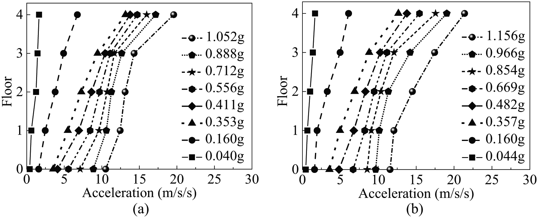
Maximum acceleration distributions of the tested models: (a) RC frame and (b) ECC/RC composite frame.
The dynamic magnification factor of the structure, namely, the ratio between the peak roof acceleration and PGA, progressively decreased with increasing PGA due to the increasing energy dissipation and decreasing stiffness. The stiffness reduction elongated the natural period and reduced the acceleration responses. The dynamic magnification factor decreased very slightly in the first two loading conditions. Then, this decrease continued at a higher rate, as shown in Figure 14. Because application of ECC could effectively decrease the roof accelerations, the dynamic magnification factors of the ECC/RC composite frame were initially smaller than those of the RC frame. However, much more damage and stiffness degeneration occurred in the RC frame with increasing the PGA, the dynamic magnification factor of the RC frame decreased more rapidly than that of the ECC/RC composite frame. In the last two loading conditions, the RC and ECC/RC composite frames had very similar dynamic magnification factors.
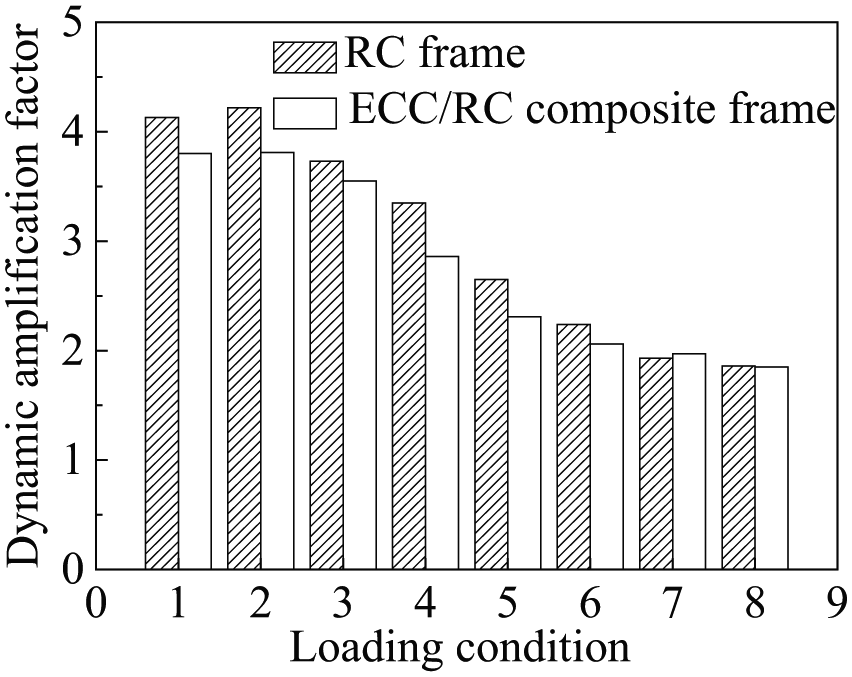
Variation of the dynamic magnification factors of the tested models.
Shear force response
The shear force can be calculated as the sum of the upper floor inertia forces, which were obtained from multiplying the recorded acceleration by the floor mass. Figure 15 shows the maximum base shear forces at different PGAs. The maximum base shear force of each frame progressively increased with increasing PGA, while the rate of increase continually decreased. After the fourth loading condition, the slopes of the curves approached zero as a consequence of the progressive yielding of the structural members. During the whole loading process, the maximum base shear force–PGA curve of the ECC/RC composite frame was above the curve of the RC frame, and their gap increased with the PGA. In the first few loading processes, the fundamental periods of the two tested models were less than the predominant period of the Taft wave (0.34 s). The fundamental period of the ECC/RC composite frame was closer to the predominant period and it had a larger seismic response compared with the RC frame. Then, the fundamental periods gradually increased and became larger than the predominant period, especially for the RC frame with serious damage development. Thus, the shear force of the ECC/RC composite frame was still larger than the RC frame due to its larger stiffness.
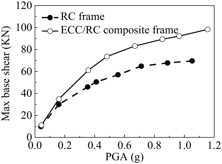
Maximum base shear force–PGA curves of the tested models.
Conclusion
This article presented the seismic responses of a precast RC frame and an ECC/RC composite frame from shaking table tests. The following conclusions can be drawn from the experimental results in this article:
After being subjected to strong earthquake motions, the tested models maintain good performance, and the connection areas retain their integrity. The tested models obey the principles of “strong column/weak beam” and “strong shear/weak flexure.” The method adopted in this test is reliable and can be applied in the seismic design of precast RC frames.
Compared with the RC frame, the ECC/RC composite frame has fewer stirrups in the beam-to-column joints and the bottom columns. But it shows fewer flexural-shear cracks in the joint zones. No ECC spalling or wide macro-cracks were observed in the ECC/RC composite frame. Using ECC can significantly improve the shear resistance and decrease the structural damage.
During the loading process, the natural frequency, stiffness, and dynamic magnification factor of the ECC/RC composite frame decreased more gradually than those of the RC frame. Moreover, the ECC/RC composite frame exhibited higher equivalent damping ratio and absolute displacements and, lower inter-story drifts and roof acceleration. These results indicate that, compared to the RC frame, the ECC/RC composite frame has better damage resistance, less stiffness reduction, and higher deformation capacity and energy dissipation ability. Using ECC in beam–column joints and bottom columns greatly improved the seismic performance of the precast RC frame.
Footnotes
Declaration of Conflicting Interests
The author(s) declared no potential conflicts of interest with respect to the research, authorship, and/or publication of this article.
Funding
The author(s) disclosed receipt of the following financial support for the research, authorship, and/or publication of this article: Financial support of this work by Distinguished Young Scholar Foundation of Jiangsu Province under BK20160027, Priority Academic Program Development of Jiangsu Higher Education Institutions under 1105007002, National Natural Science Foundation of China under 5177 8131 is gratefully acknowledged.