
Abstract
To improve the flutter stability of a long-span suspension bridge with steel truss stiffening girder, two vertical stabilizers of which the total height reaches to approximately 2.9 m were planned to install on the deck. As the optimized girder presents the characteristics of a bluff body more, its vortex-induced vibration needs to be studied in detail. In this article, computational fluid dynamics simulations and wind tunnel tests are carried out. The vortex-shedding performance of the optimized girder is analyzed and the corresponding aerodynamic mechanism is discussed. Then, the static aerodynamic coefficients and the dynamic vortex-induced response of the bridge are tested by sectional models. The results show that the vertical stabilizers could make the incoming flow separate and induce strong vortex-shedding behind them, but this effect is weakened by the chord member on the windward side of the lower stabilizer. As the vortex-shedding performance of the optimized girder is mainly affected by truss members whose position relationships change along the bridge span, the vortex shed from the girder can hardly have a uniform frequency so the possibility of vortex-induced vibration of the bridge is low. The data obtained by wind tunnel tests verify the results by computational fluid dynamics simulations.
Keywords
Introduction
With the increase of bridge span, long-span bridges are more flexible and sensitive to wind effects. Vortex-induced vibration is a typical structural response, which may lead to fatigue damage of components and accidents of vehicles. A number of cable-supported bridges had been reported suffering from this vibration once, such as the Deer Isle Bridge with a H-type girder (Kumarasena et al., 1991), the Great Belt Bridge with a streamlined box girder (Larsen et al., 2000), the Second Severn Crossing Bridge with a steel–concrete composite girder (Macdonald et al., 2002), and the Xihoumen Bridge with a separated twin-box girder (Li et al., 2011). Adding baffle plates, stiffening systems of cables or guide vanes can effectively weaken and even inhibit their vortex-induced responses. Theoretical analyses, wind tunnel tests, numerical simulations, and field experiments are common research methods. Comprehensive investigations on the mechanism of vortex-induced vibration have been carried out and a lot of remarkable achievements have been made (e.g. Belloli et al., 2014; Hua et al., 2015; Komatsu and Kobayashi, 1980; Kwok et al., 2012; Matsumoto et al., 1993; Nakagawa and Nakagawa, 1993; Xin et al., 2012; Zhang et al., 2016; Zhou et al., 2017; Zhu et al., 2017).
Currently, increasing number of long-span bridges are constructed in complicated mountainous canyon area. Due to the limited conditions of transportation and construction site, steel truss stiffening girders are widely used in these bridges. Truss girders are composed of a great many crisscrossed members and have high ratios of porosity, so it seems that they have good performance against the vortex-induced vibration. On the other hand, however, these bridges are more likely to be suffered from strong winds with large angles of attack. To improve their flutter stability, vertical stabilizers are always added to the deck. For the 538 m Dimu River Bridge (Wang et al., 2014), the 636 m Beipan River Bridge (Hu, 2006), and the 900 m Sidu River Bridge, each of them has a vertical stabilizer below their decks, and the heights of the stabilizers are 1, 1, and about 0.8 m, respectively. For the 1176 m Aizhai Bridge (Chen et al., 2009) and a 1100 m suspension bridge being built (Tang et al., 2017), the vertical stabilizer is composed of two parts, the upper one above the deck and the lower one below the deck, and the height reaches to 2 m and about 2.9 m, respectively. These vertical stabilizers installed along the bridge span make the truss girder present the characteristics of a bluff body more, calling for further investigations on the vortex-induced vibration. Tang et al. (2018) simplified the actual girder as an ideal thin flat plate to analyze the effect of the vertical stabilizer on structural aerodynamic stability and found that higher vertical stabilizers increase the possibility of vortex-induced vibration or galloping. Therefore, it is very necessary to study the performance of vortex-induced vibration of the truss girder with high vertical stabilizers.
In this article, the vortex-induced vibration of the 1100 m suspension bridge introduced above is studied. Computational fluid dynamics (CFD) simulations are first carried out to analyze the vortex-shedding performance of the truss girder with high vertical stabilizers. After discussing the possibility of vortex-induced vibration of the bridge and understanding the corresponding aerodynamic mechanism, wind tunnel tests are then implemented to measure the static aerodynamic coefficients and the dynamic vortex-induced response of the bridge at different angles of attack.
Engineering backgrounds
A suspension bridge with steel truss stiffening girder being built is located in a river valley with deep canyon area. The total length of the bridge is about 1411 m and its main span is about 1100 m. The steel truss stiffening girder with a width B of 27 m and a height H of 8.2 m is suspended by hangers at intervals of 10 m. The deck is made up of longitudinal steel I-beams and concrete slabs. To improve the flutter stability of the bridge (Tang et al., 2017), the gap of the deck was closed by a steel plate, and a vertical plate with a height of 1.36 m was installed above the horizontal plate. Furthermore, another vertical plate with a height of 1.5 m was installed below the deck as well. These two vertical plates installed along the bridge span are called as the upper and lower vertical stabilizers, as shown in Figure 1. As the height of the stabilizers reaches to about 2.9 m, however, the optimized girder should further present the characteristics of a bluff body.

Cross-section of the steel truss stiffening girder (mm).
To understand the dynamic characteristics of the suspension bridge, a three-dimensional (3D) finite element model is established using ANSYS software, as shown in Figure 2. The members of steel truss stiffening girder and the bridge towers are simulated by BEAM4 elements. The deck and other affiliated members are simulated by MASS21 elements. The total dead load of the girder including the deck and other affiliated members is 300.9 kN/m. The cables and suspenders are simulated by LINK8 elements. Each of the cables contains 17,017 lengths of wire with a tensile strength of 1860 MPa. The frequencies of some typical modes are listed in Table 1.
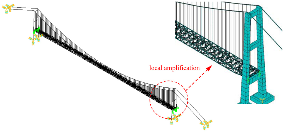
Three-dimensional finite element model.
Modal frequencies and shapes of the bridge.

S: symmetric; AS: antisymmetric; V: vertical; T: torsional.
Analysis by CFD simulations
Before wind tunnel tests, CFD simulations are carried out to analyze the vortex-shedding performance of the optimized girder. Due to complexity of the establishment of a 3D truss girder model, two-dimensional (2D) models are established. The scale ratio of girder model in wind tunnel tests is 1/43.63, which will be discussed later, so the same ratio is adopted in CFD simulations. The girder consists of three components, the steel truss, the deck, and other affiliated members. For the deck, the cross-sectional size has little change along the bridge span, so a 2D CFD model can well represent its aerodynamic characteristics. The vortex-shedding performance of the deck with high vertical stabilizers is calculated. For the steel truss which composes of many crisscrossed members, a 2D CFD model can hardly represent its aerodynamic characteristics, and the aerodynamic interference among its members is studied. Finally, the effects of the steel truss and other affiliated members on vortex-shedding performance of the deck are analyzed, and the possibility of vortex-induced vibration of this suspension bridge is further discussed.
Effects of the vertical stabilizers
The computational domain and boundary condition used in this study are shown in Figure 3. The computational domain is assumed to be 8.5B in the mean-flow direction and 5.5B in the cross-flow direction, where B is the girder width with the reduced scale. The windward and the leeward sides are set as velocity-inlet and pressure-outlet boundaries, respectively, and the bridge deck is set as a smooth wall boundary. The computational domain is discretized by quadrilateral structured and unstructured meshes. A boundary layer with three rows clinging to the bridge deck is set. The mesh size progressively increases from the sides of the bridge deck to the computational boundaries, as shown in Figure 3. Four cross sections, that is, the original deck, the deck with the upper stabilizer, the deck with the lower stabilizer, and the deck with both the upper and lower stabilizers, are calculated, of which the mesh numbers are 195,383, 200,340, 158,524, and 209,540, respectively. The Reynolds-averaged Navier–Stokes equations are performed using the k–ω shear stress transport (SST) model. Such model is known to provide more accurate results, if compared to standard k–ω and k–ε models, in external aerodynamic cases which involve boundary layer separation (Miranda et al., 2015). The dimensionless time-step is set equal to 10−4. The discretized problem is numerically solved using a semi-implicit method for pressure-linked equations (SIMPLE) pressure–velocity coupling algorithm. A second-order scheme is selected for pressure, and a second-order upwind scheme is selected for momentum, turbulent kinetic energy, and specific dissipation rate. The CFD software FLUENT is used in the simulation.

Computational mesh of the CFD model.
For the cross-section of the bridge deck, the lift coefficient is defined as
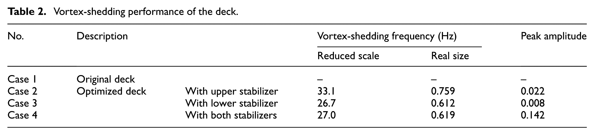
Here, 0° angle of attack and 15 m/s wind velocity are selected. The time series of lift coefficients of the four cross sections are shown in Figure 4. For the original deck without vertical stabilizers, vortices fill the gaps between the longitudinal I-beams below the deck, so the cross-section is like a rectangle plate. As the ratio of this plate width to thickness is large, vortex-shedding does not occur and the lift coefficient of the deck is a constant. Figure 5(a) shows the contour of the mean static pressure. Due to the vortices below the deck, especially for those on the windward side, the lift force of the cross-section is negative, that is, downward. When the upper stabilizer is added, it makes the flow above the deck separate, inducing vortex-shedding behind it, as shown in Figure 5(b). As the cross-section becomes bluff, the lift coefficient is fluctuant and its dominant frequency which represents the vortex-shedding frequency is 33.1 Hz. The upper stabilizer has little effect on the vortices formed stably between the longitudinal I-beams below the deck and the average lift force of the cross-section is still negative. When the lower stabilizer is added, vortex-shedding also occurs, as shown in Figure 5(c). The vortex-shedding frequency behind the lower stabilizer (26.7 Hz) is smaller than that behind the upper stabilizer. The lower stabilizer affects the existence of the vortices between the longitudinal I-beams, and the average lift force of the cross-section becomes positive. When both the upper and lower stabilizers are added, however, the high vertical plates make the deck further present the characteristics of a bluff body. The vortex-shedding phenomenon becomes very obvious, as shown in Figure 5(d), so the amplitude of lift coefficient of the cross-section increases significantly. The average lift coefficient of the cross-section with the two stabilizers is closer to that of the cross-section with the lower stabilizer only, and so does the vortex-shedding frequency (27.0 Hz). Table 2 summarizes the vortex-shedding frequencies of the four cross sections. According to the same Strouhal number at different Reynolds numbers, the vortex-shedding frequencies for the real size of the deck can be converted, as shown in Table 2. If considering the aerodynamic force of the deck only, the lock-in wind speeds for the first three symmetric vertical bending modes of the bridge with the upper and lower stabilizers are 3.6, 5.0, and 7.5 m/s, respectively. However, such incoming flow conditions are very common in this bridge site according to our measured and experimental data.

Time series of lift coefficients of the deck.
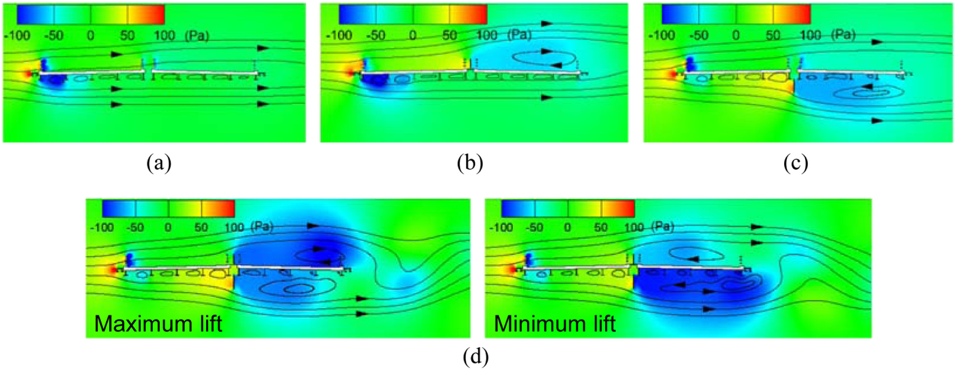
Contours of static pressure of the deck: (a) original deck, (b) deck with upper stabilizer, (c) deck with lower stabilizer, and (d) deck with both upper and lower stabilizers.
Vortex-shedding performance of the deck.
Aerodynamic interference among truss members
According to the arrangement of truss members, two situations are considered. The first case includes the chord member and the tilted web member, as their centerline is perpendicular to the direction of incoming flow. The second case includes the chord member and the link bar member, as their centerline is parallel to the direction of incoming flow, as shown in Figure 6. As the distances among these truss members change along the bridge span, different L1 and L2 need to be considered.

Composition of the steel truss: (a) front view, (b) vertical view, and (c) side view.
The computational domains and parameters of the two cases are similar to those of the previous case, and the details are omitted for brevity. The lift coefficient of each member is defined as
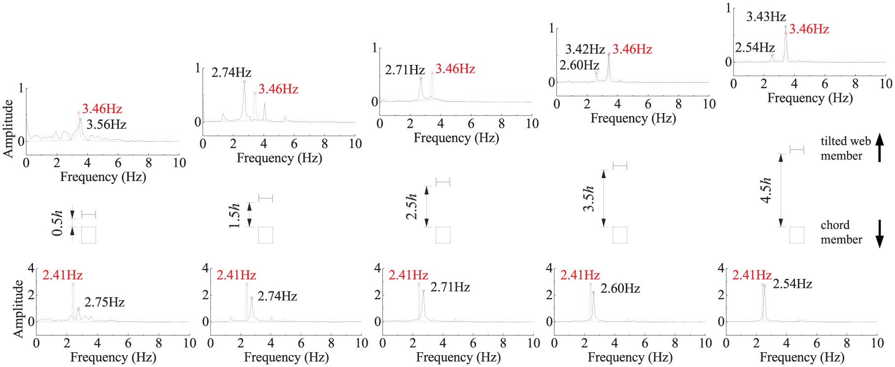
Amplitude spectrums of members in parallel arrangement (red lines: single cross-section; black lines: two cross sections).
For the second case, four cross sections in tandem arrangement, including two chord members and two link bars, are selected, and the distance L2 increases from 2b to 16b, where b is the width of the chord member. Figure 8 shows the amplitude spectra of time series of lift coefficients, in which the abscissa has been converted to actual frequencies corresponding to prototype. According to the flow direction, the four cross sections are called as upstream chord, upstream link bar, downstream link bar, and downstream chord, respectively. For the upstream chord, its vortex-shedding performance is almost unchanged, especially when L2 is larger than 4b. However, the wake of the upstream chord suppresses the vortex-shedding of the other three cross sections on the leeward side, having great effects on their aerodynamic characteristics. Affected by the vortex shed from the upstream chord, a spectral peak with the same dominant frequency as the upstream chord but smaller amplitude can be observed in the amplitude spectrum of the upstream link bar. The amplitude of this spectral peak decreases with the increase in L2. As the downstream link bar and chord are far away from the upstream chord, they are less likely to be affected by its vortex-shedding, and there is no obvious spectral peak observed in their amplitude spectra.
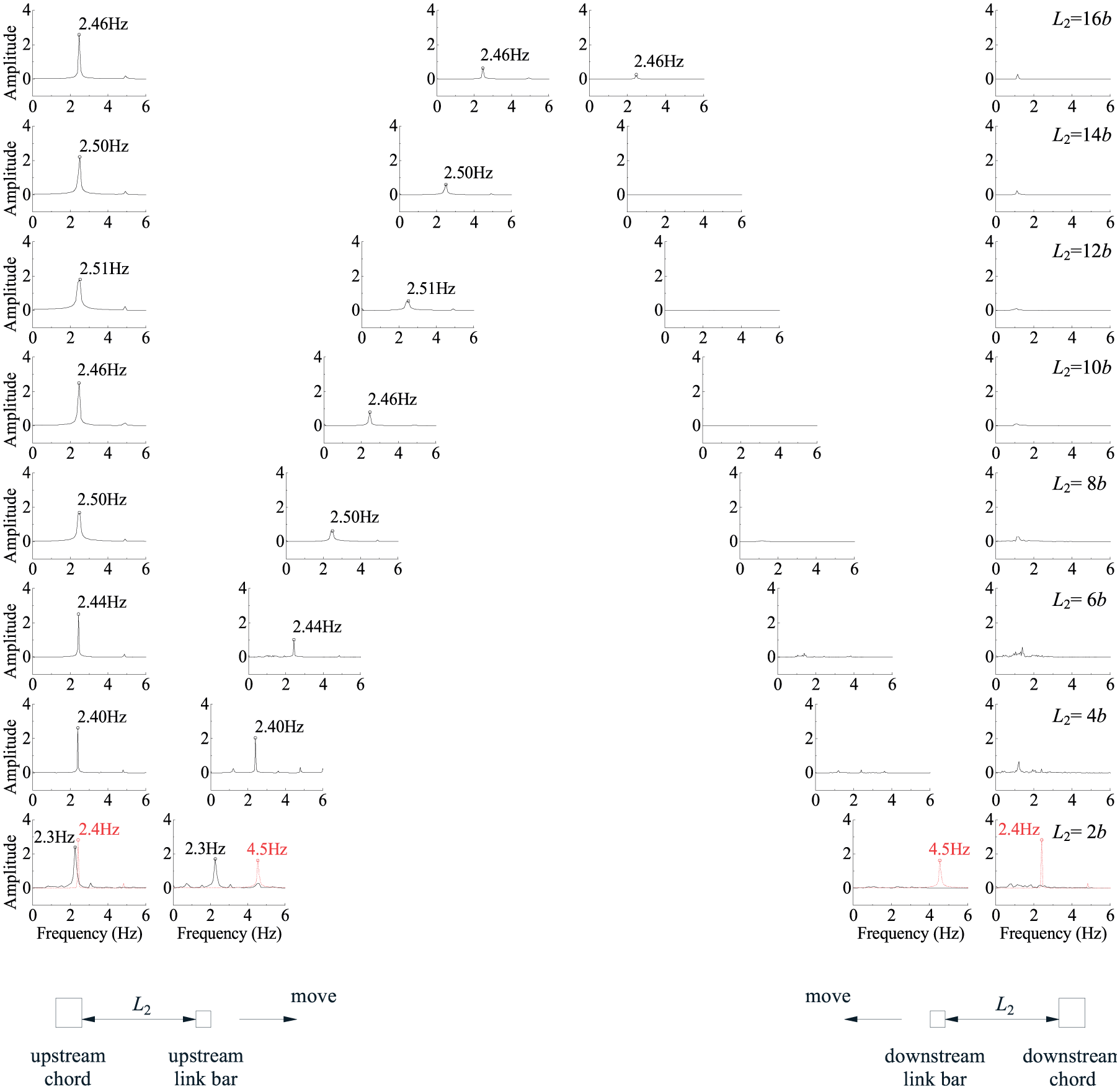
Amplitude spectrums of members in tandem arrangement (red lines: single cross-section; black lines: four cross sections).
Effects of the steel truss
Based on the above analyses, we know the difference of the vortex-shedding performance between the deck and the steel truss. The lift force of the deck is divided by B to obtain the lift coefficient, while the lift forces of the truss members are divided by b. Therefore, the peak amplitudes in Figures 7 and 8 should be divided by B/b (about 39) when they are compared with the values in Table 2. The deck with the stabilizers has a larger size so its vortex-shedding frequency is relatively small but peak amplitude is large, which makes the suspension bridge has the possibility of vortex-induced vibration at common inflow conditions. The truss members have smaller sizes so their vortex-shedding frequencies are relatively large but peak amplitudes are small.
Due to the big difference of the vortex-shedding performance, it is necessary to study the aerodynamic interference between the deck and the steel truss. To solve this question, the deck, the steel truss, and other affiliated members including the maintenance road and the rail of inspection vehicles are considered simultaneously. As the distances among the truss members change along the bridge span, we need to choose some typical cross sections for study. The midst of a truss segment divided by the vertical web members is chosen, including two cross sections for which the positions of the link bars are different. The computational domains and parameters of the two CFD models remain unchanged. The lift coefficient of the whole cross-section is defined as

Contours of mean static pressure of the girder: (a) cross-section 1 and (b) cross-section 2.
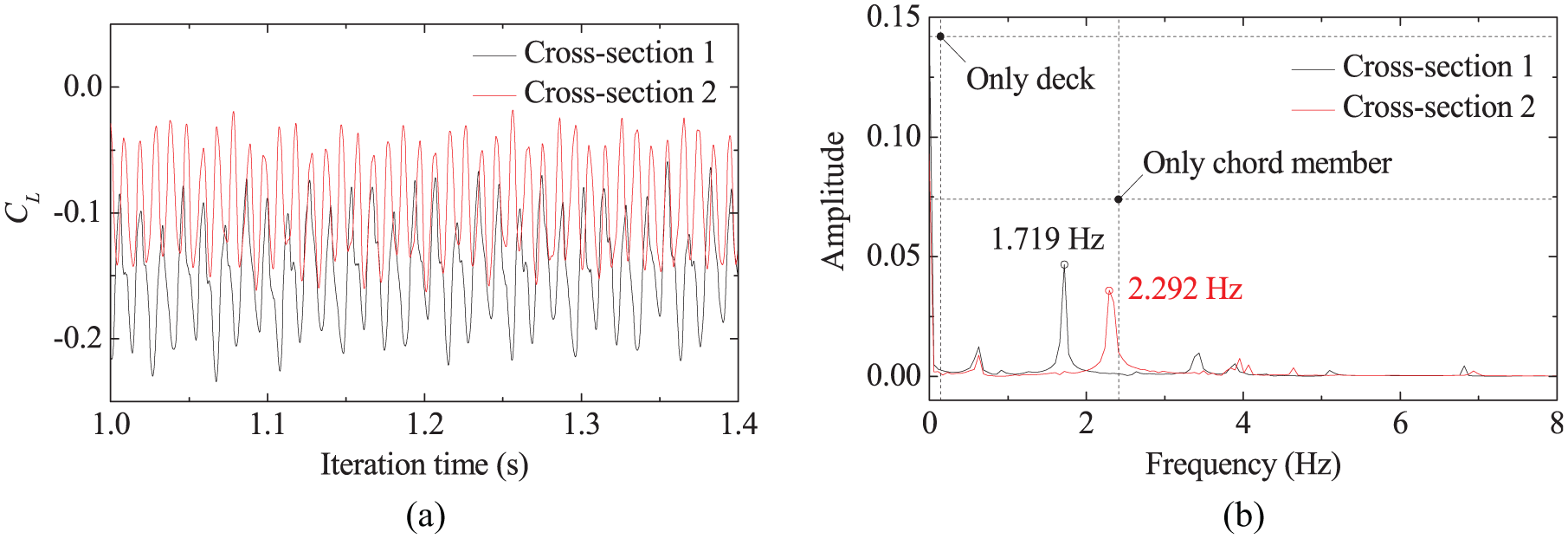
Time series and amplitude spectrums of lift coefficients of the girder: (a) time series and (b) amplitude spectrums.
The vortex-shedding performance of the whole girder is more affected by the steel truss from the view of values of the dominant frequency and peak amplitude. It seems that the vortex shed from the stabilizers is inhibited under the effect of the steel truss. As the cross sections in parallel arrangement have relatively small aerodynamic interference, this inhibition must be caused by the upstream chord member on the upper side. In the previous analysis, we mentioned that the upper and lower vertical stabilizers make the flow separate, inducing strong vortex-shedding behind them, and the lower stabilizer takes the leading role in the vortex-shedding performance. Here, the upstream chord makes the flow separation in advance. The lower stabilizer is located in the chord wake and has less hindrance to the incoming flow, so the vortex-shedding caused by the two stabilizers is obvious weakened.
According to the vortex-shedding frequencies of the two cross sections, the maximum lock-in wind speeds for the first three symmetric vertical bending modes of the bridge are just 2.7 and 2.0 m/s, respectively. In this situation, the resonance possibility of the suspension bridge is small due to the low vortex lock-in wind speed. Moreover, there is an obvious difference of the vortex-shedding performance between the two cross sections, so the vortex shed from the girder can hardly have a uniform frequency because position relationships among truss members change along the bridge span. The resonance possibility of the suspension bridge further decreases.
Verification by wind tunnel tests
In this section, a wind tunnel test program is implemented to study the aerodynamic characteristics of the truss girder with high vertical stabilizers. As mentioned previously, the girder model made of wood and plastic has a geometric scale ratio of 1/43.63 and a length of about 2.1 m. All tests were carried out in a closed-circuit high-speed test section (XNJD-1), which has a 2.4 m (width) × 2 m (height) × 16 m (length) working section.
Static aerodynamic coefficients
The static aerodynamic coefficients of the girder with high vertical stabilizers were first tested, as shown in Figure 11. Different angles of attack were realized by keeping the direction of incoming flow unchanged while rotating the girder model. For the girder model, the drag, lift, and moment coefficients corresponding to the wind coordinate system are defined as
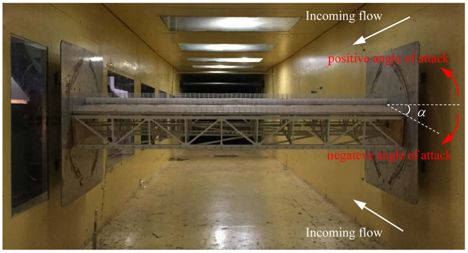
Sectional model for static aerodynamic coefficients test.
In the wind tunnel tests, the approaching flow condition was uniform smooth flow with a wind velocity of about 15 m/s. The static aerodynamic coefficients of the steel truss and the whole girder with the vertical stabilizers are shown in Figure 12. The steel truss which does not contain the deck and other affiliated members has good ventilated performance, so its aerodynamic coefficients are relatively small.
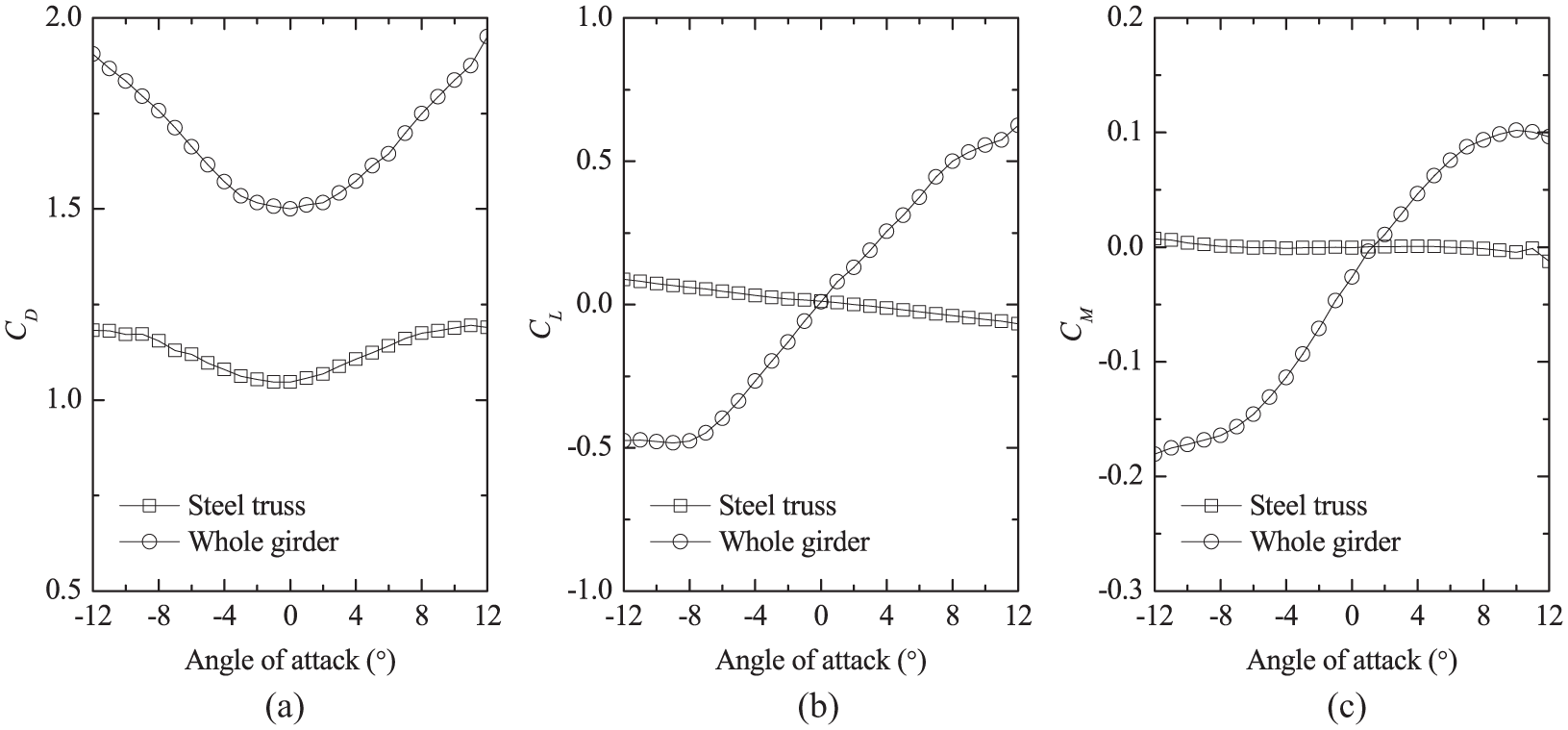
Aerodynamic coefficients versus angle of attack: (a) drag coefficient, (b) lift coefficient, and (c) moment coefficient.
Vortex-induced vibration
The vortex-shedding vibration of the girder with high vertical stabilizers was tested based on a sectional model, as shown in Figure 13. The girder model was rigidly fixed to two steel brackets which are hanged by eight springs installed at the exterior of the tunnel. This test system allows the girder to vibrate in heaving and torsional directions. The equivalent mass of the model is 19.19 kg per meter, and the equivalent mass moment of inertia is 1.17 kg m2 per meter. The vertical and torsional frequencies of the model are 1.70 and 3.52 Hz, respectively, so the wind speed ratio of the real value to the experimental value is 3.83. The damping ratios of the model in vertical and torsional directions are 0.46% and 0.32%, respectively.
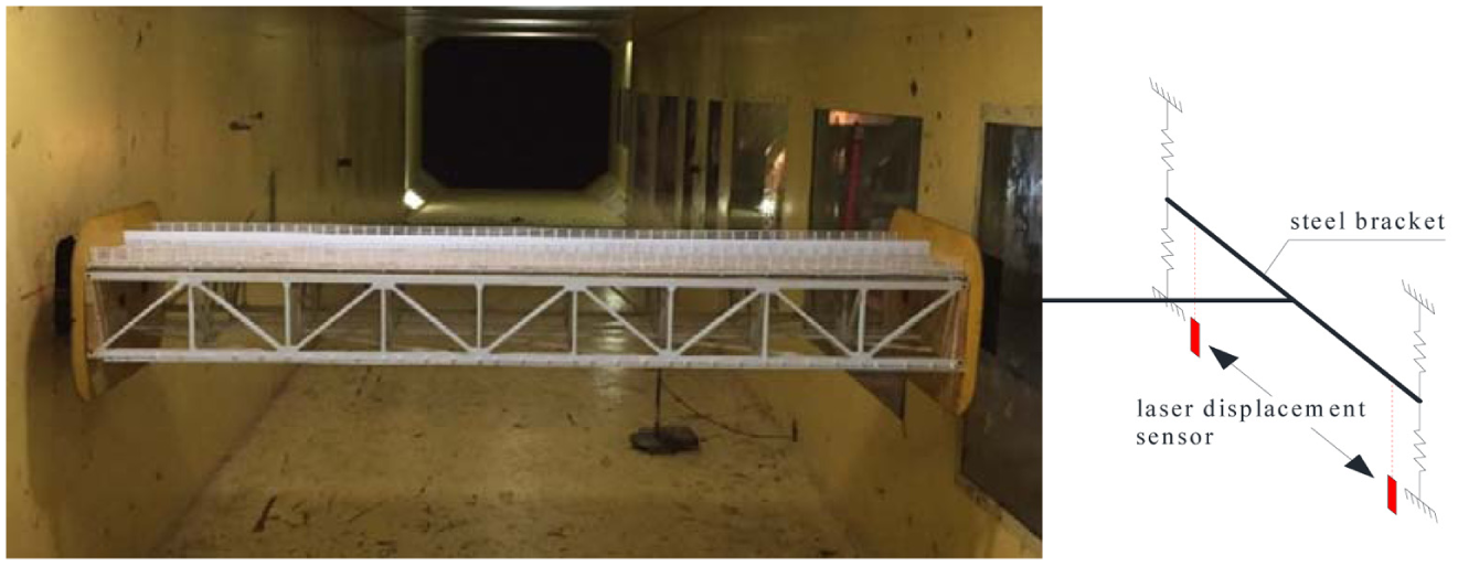
Sectional model for vortex-induced vibration test.
The wind characteristics over the bridge site were analyzed by field measurements, wind tunnel tests, and CFD simulations. The design standard wind speed at the height of the bridge girder
Maximum RMS displacements for vertical and torsional vibrations.
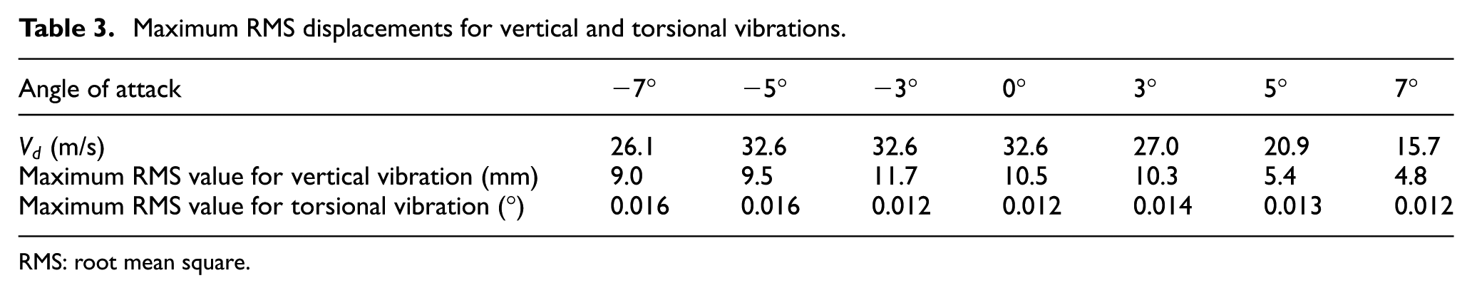
RMS: root mean square.
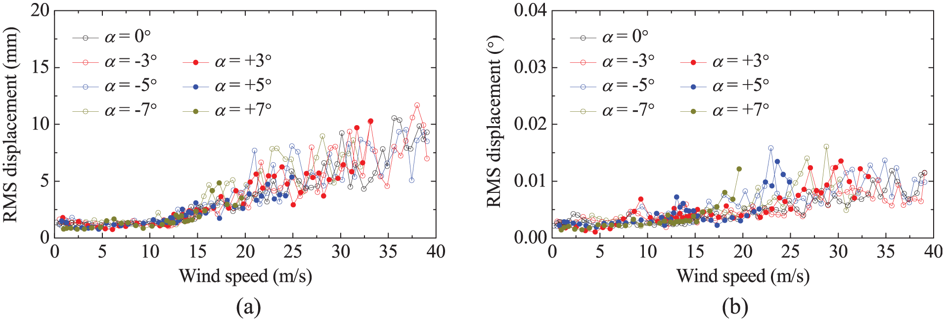
RMS displacements for vertical and torsional vibrations: (a) vertical amplitude and (b) torsional amplitude.
In Figure 14, no lock-in region for vortex-induced vibration is observed, and the RMS displacements mainly reflect the buffeting responses caused by the shedding vortices since the incoming flow in wind tunnels is uniform. For both the vertical and torsional vibrations, the RMS displacement increases with the increase in wind velocity in general, but it also shows a certain level of fluctuation because of the random of the vortices shed from the girder. According to the Chinese design code (JTG/T D60-01-2004, 2004), the allowable amplitude for the vertical vibration
Conclusion
To improve the flutter stability of a long-span suspension bridge with steel truss stiffening girder, an upper and a lower vertical stabilizers are installed on the center of the bridge deck. The vortex-induced vibration of the optimized girder with high vertical stabilizers is studied by both CFD simulations and wind tunnel tests. The original deck has a large ratio of width to thickness and is like a streamlined plate. The two vertical stabilizers make the flow above and below the deck separate, inducing vortex-shedding behind them, and the lower stabilizer takes the leading role in the vortex-shedding performance. The vortex-shedding has a relatively small frequency but large amplitude, which makes the bridge have the possibility of vortex-induced vibration at common inflow conditions. Actually, the flow below the deck will be separated in advance due to the existence of the chord member on the windward side of the lower stabilizer. As the lower stabilizer is located in the wake of the chord member, it has less hindrance to the incoming flow, and the vortex-shedding caused by the two vertical stabilizers is obvious weakened. Therefore, the vortex-shedding performance of the whole girder is mainly affected by the steel truss rather than the deck. The steel truss is composed of a great many crisscrossed members, and the aerodynamic interference among these members is strong and closely related to their distances which, however, change along the bridge span. Therefore, the vortex shed from the girder can hardly have a uniform shedding frequency, and the possibility of vortex-induced vibration of the bridge is low.
Footnotes
Declaration of Conflicting Interests
The author(s) declared no potential conflicts of interest with respect to the research, authorship, and/or publication of this article.
Funding
The author(s) disclosed receipt of the following financial support for the research, authorship, and/or publication of this article: The authors are grateful for the financial supports from the National Natural Science Foundation of China (51708463, 51525804), the Construction Technology Project of China Transport Ministry (2014318800240), and the Sichuan Province Youth Science and Technology Innovation Team (2015TD0004).