
Abstract
Starting from the Building Information Model, a pre-processing procedure is proposed in this work to develop the refined finite element model of buildings and building community. The structural members which are represented by three-dimensional solid entities in Building Information Model are converted to lines and planes according to their geometric characteristics. To meet the requirements of finite element analysis of building structures, the lines are discretized by the beam elements and the surfaces are discretized by the shell elements. The damage plasticity model is implemented to simulate the damage and failure of concrete, and the classic plasticity model is chosen for steel. The simulations of high-rise building and building community are performed with the help of large computing server. The damage patterns of different building structures are obtained and discussed. This study lays a solid foundation for the further fusion between Building Information Model and finite element analysis.
Keywords
Introduction
Building Information Modeling
In general, Building Information Modeling (BIM) is a digital representation of physical and functional characteristics of facilities. Although the information management is emphasized in BIM, the widely used BIM software/system, for example, Revit and Rhino, is mainly developed based on CAD, that is, computer-aided design, in the current stage. Thus, the technology foundations of the current BIM system are CAD and database. The traditional CAD in building engineering is mainly based on two-dimensional (2D) graphics and line drawings. Especially for the regular building project, the 2D design drawings could be easily developed based on the concept of floor/level. On the other hand, the 2D drawings are somewhat too abstract, and too much information is lost. To understand the whole building model based on 2D building drawings, the human interpretation and imagination are needed. Thus, the traditional CAD could not be easily used in management. To meet the requirements of modern construction industry, the current BIM system is developed. The 3D graphical model is developed for each element of building. The detailed geometric information is included in the developed 3D graphical model. As we know, people could read 3D graphics and understand it without much of professional interpretation. Thus, people of different specialties, for example, architect, engineer, manager, and owner, could work together on a universal 3D building model. Moreover, the universal 3D building model carries massive volume of data and information. Thus, the large-scale database is introduced to manage the data and information associated with the 3D building model. Thus far, the foundations of BIM system have been developed. Then, we could develop higher level data structure to fulfill the requirements from different specialties in an efficient way. For example, the collisions of pipelines in a building could be easily detected based on the well-defined 3D pipeline data. Another example is the construction process of a building, which could be simulated based on the current BIM system by adding up the elements, members, and works step by step.
The history of BIM could be traced to 1970s. The pioneering works of Eastman et al. (1974) laid the foundation of BIM. In 1980s and 1990s, the concept and theory of BIM developed continuously by the academia (Aish, 1986; Tolman, 1999; Van Nederveen and Tolman, 1992). In the first 10 years of the new century, the industry paid more and more attention to BIM and the BIM software was developed and widely used. In recent years, McGraw Hill (2014) demonstrates that most of the contractors confirm that the investment to the BIM is worthy and efficient in the project management. In the recent years, people start to think the extension of BIM with the help of modern computer science and facilities. The concept of CIM, that is, City Information Model, has been proposed and accepted by many people. CIM is usually considered as super-BIM or BIM in city level. The 3D models of buildings, roads, public spaces (open data), street lights, or even people on the street (social media) are included in CIM with massive volume of data and information. According to Khemlani (2016), a CIM model could enable city-wide simulation (for architects and planners) of various aspects such as traffic, congestion, energy, and impact of natural disasters, such as earthquakes or hurricanes and flood control. Also, the development and further evolving of city could be simulated by CIM, based on which the government could make decision in a more reasonable way.
Finite element analysis
In the engineering practice, not only CAD but also CAE (computer-aided engineering) play essential roles. CAD is about creation/generation of the 3D model in the viewpoint of design. CAE is about testing/simulating the characteristics (material, strength, fatigue, etc.) using engineering methods. In the mathematical point of view, CAD deals with the algebra problems in engineering and CAE deals with the analysis problems in engineering. In an algebra problem, we just consider simple operation of sets. In an analysis problem, we should consider differentiation and integration, or more specifically, partial differential equation (PDE). For example, the structural analysis and heat transfer of buildings are usually based on PDEs. The current CAE platforms, for example, ABAQUS, Ansys, Etabs, are mainly developed based on finite element method (FEM).
FEM is a class of numerical techniques for finding approximate solutions to boundary value problems for PDEs (Belytschko et al., 2013; Hughes, 2012). To solve the problem, FEM subdivides a large problem into smaller, simpler parts that are called finite elements. The simple approximate solution of the problem is developed for each element, and the entire problem is modeled by assembling all the finite elements. The finite element analysis (FEA) of large system usually needs a large amount of computational recourses and time. To save computational expenses and improve accuracy, the finite elements may not be developed in the real 3D entity of the structure. Thus, the one-dimensional (1D) line element family (Feng et al., 2015, 2017; Feng and Ren, 2017; Spacone et al., 1996) is developed for truss, beam, and column. And, the 2D shell/plate element family (Hsu and Mo, 2010; Reddy, 2004; Vecchio and Collins, 1986) is developed for slab and shear wall. The 1D and 2D element families are often referred as structural element because they are commonly used in the simulation of structures. The finite element simulation of buildings structure is commonly based on structural elements, for example, beam element and shell element, due to the trade-off between accuracy and expense. The pioneering works for the simulation of super high-rise buildings based on beam elements and shell elements could be found in the works by Lu et al. (2013, 2011) and Huang et al. (2017).
From BIM to FEA
As we know, CAD model and CAE model are quite different from each other, even though they describe the same entities. Sometimes, we use the word “export” to describe the conversion of models from CAD to CAE. Actually, in the engineering practice of early years, the word “export” was too good. Engineers would rather rebuild the model for CAE based on CAD, especially in building engineering for which we just have 2D CAD drawings. Engineers just imagine the 3D model in their mind based on 2D CAD drawings and build them in CAE software with consideration of physics and mathematics. Thus, the conversion between CAD and CAE is estimated to take over a large amount of time and works in the design of building structure. CAD model and CAE model of a building are not separate from each other. The design details in CAD model are based on the results of CAE. In the meanwhile, the change of details in CAD model may alter the results of CAE very much. The iterations between CAD and CAE are often headaches for the designers of buildings.
At present, we have BIM as the next generation of CAD. Thus, we may ask whether one could improve the development of CAE model with BIM. As we know, BIM is a real 3D model with complete geometric information. Thus, from BIM to CAE model, we may just need to remove the redundant information and consider reasonable simplification. With the help of database, we may perform this work more efficiently. Actually, we should state that the hand works of human are still substantial during the conversion between BIM and CAE. But the efficiency is improved and the modeling of larger buildings or even building community is possible with the help of BIM model. In this work, the procedure to generate the finite element models of buildings based on BIM model is defined. With the help of BIM model, the refined finite element model of a building community is developed. The performance of the building community under severe earthquakes is simulated and discussed.
Model export/conversion
In the current stage, the totally automatic conversion from BIM to FEA model is somewhat unrealistic. Thus, in this work, we consider the strategy of model conversion which requires human involvement but makes full use of BIM model. The total procedure could be considered as redundant information removal and model dimension reduction. The key steps for the model conversion could be considered as follows.
Geometry cleanup
The BIM is developed to manage comprehensive information of building. The structural analysis usually does not need so much information. As the first step in geometry cleanup, the redundant information within the BIM should be removed. Figure 1 shows a relatively simple BIM for a building project. In the structural design of this building project, we really do not need so much information. Thus, the redundant information removal is needed. On the other hand, how to define the redundant information is somewhat problem dependent so that the human judgment is required. In this example, it is easy even for an amateur to remove the trees and wind turbines from the BIM. However, how to deal with the foundation soil nearby the house requires professional judgment, which is related to a very professional field named soil–structure interaction. After a series of professional judgments, we develop the structural portion of BIM model, as shown in Figure 2.
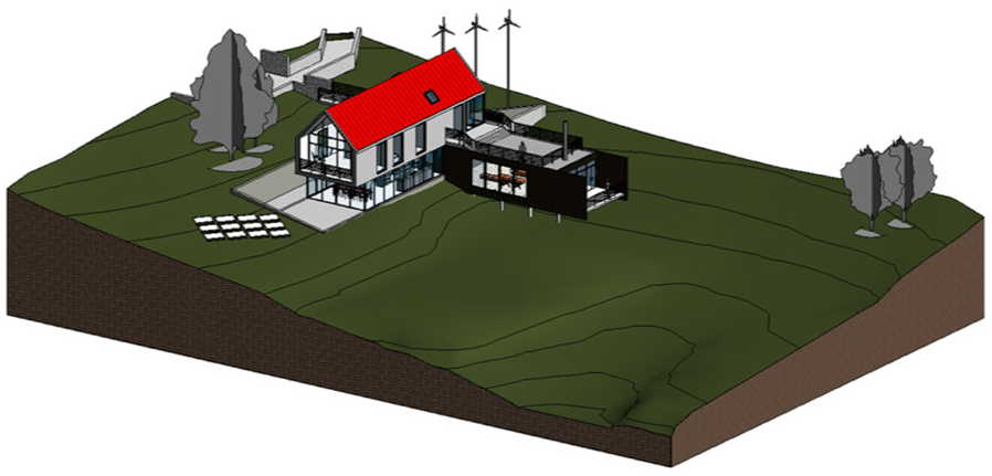
BIM model for a building project.
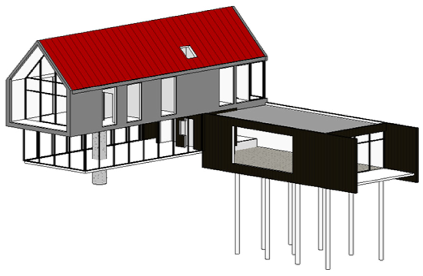
Structural portion of the BIM model.
According to the common sense of CAD, the geometry details of the building should be modeled as many as possible. Thus, even the structural portion of the BIM model still has too many details of the building, on the other hand, experience in structural analysis suggests that too many details in the geometry model may even pollute the overall results of the building structure. For example, it can be seen in Figure 3 that a hole in the wall is modeled in the BIM of the building. This hole may be designed for electric wireline or water pipeline. In the structural analysis, the wall may be modeled by shell element. If we develop the FEM mesh on a wall with a hole, the length of the smallest element should not be larger than the length of the hole. If the hole is very small, the developed FEM mesh of the wall would be very refined and requires too much of computational expense. On the other hand, the principle of structural mechanics tells us that the hole would not alter the overall behavior of the structure if it is too small. Thus, the reasonable strategy is that the small holes are neglected in the structural analysis of overall structure and reconsidered in the detail design. The structural portion of the BIM model should be further cleaned up based on knowledge of structural analysis. We can see in Figure 4 that the hole has been removed from the model.
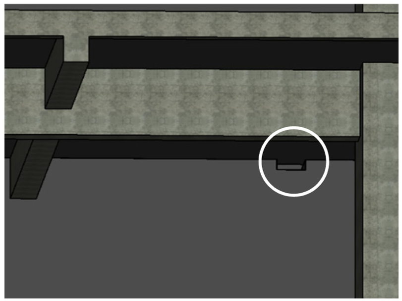
BIM model with superfluous details.
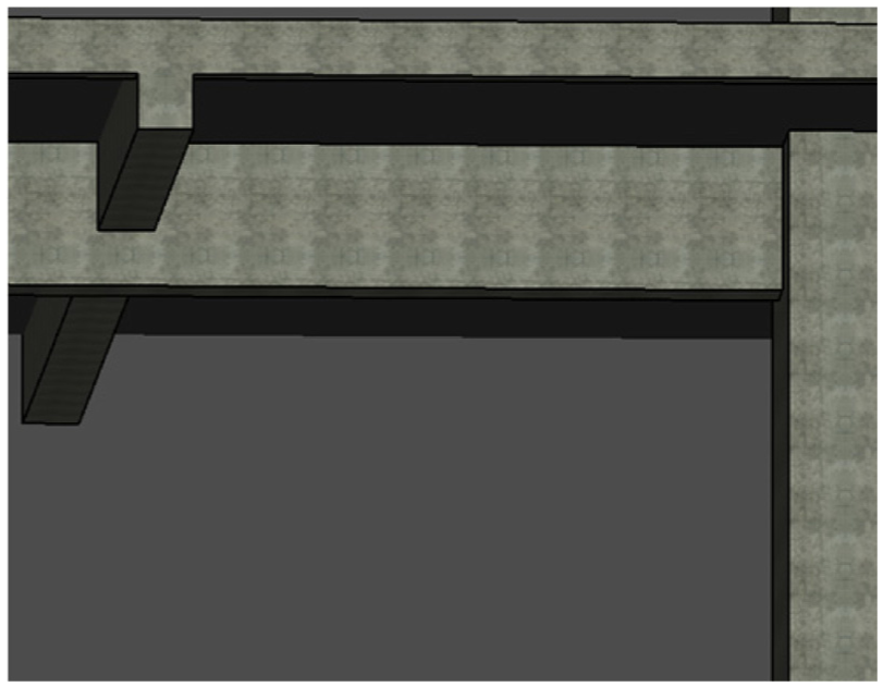
BIM model after further cleanup.
Model dimensionality reduction
The real buildings are made up of 3D entities. For the structural portion of BIM, the structural members are still modeled as 3D entities. The refined model of a 3D entity may be based on 3D solid elements. However, for most of the structural members within buildings, they are not real 3D members in the viewpoint of mechanics. For beams and columns in the building, they are modeled by the lines along the longitude directions and the deformations are described by the formulation of beam theory. And for the slabs and shear walls, they are modeled by planes or surfaces with the deformations described by the shell theory. Beam elements and shell elements are often named as structural elements in the monograph of FEM (Belytschko et al., 2013). Comparing the real 3D modeling of structural members based on solid elements, the structure elements commonly improve the computational efficiency immensely without losing too much of accuracy. Thus, most of the structural analysis and design of building structures are based on structural elements. The generation of lines, planes, and surfaces based on 3D entities of BIM is the central task of the model conversion.
Consider the beams and columns connecting in a joint shown in Figure 5. According to Figure 5(a), we could see that the section of bottom column is larger than the section of top column. But the center lines of the two columns are coincident to each other. Thus, we could develop a straight line along the center of the columns as the representative line of columns (Figure 5(b)). On the other hand, we could see different sections for different beams. If we chose the center line of each beam as the reprehensive line, different beams will connect to the column at different heights. In this scenario, the modeling of the joint could be troublesome. The top surface of each beam is at the same height, which is also the height of the level. Thus, we suggest to choose the center lines of the top surfaces of the beams as the representative lines of the beams. As shown in Figure 5(b), the representative lines of beams and columns are jointing at one point.
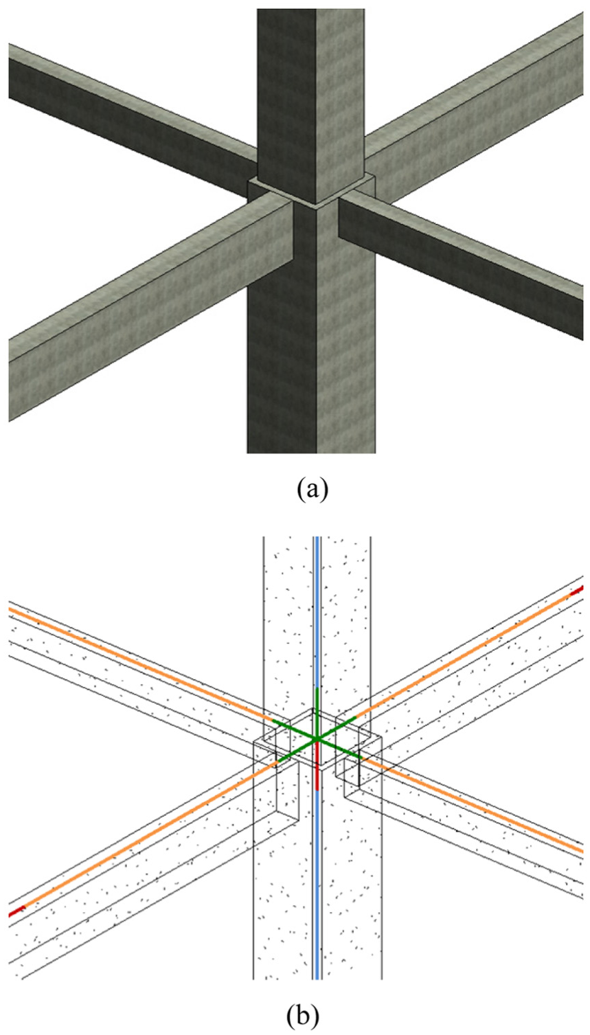
A joint with beams and columns: (a) 3D entity and (b) representative lines.
Consider the slabs and shear walls of a high-rise building, as shown in Figure 6. For the slab in 3D, we consider its top planes as the representative planes. In this way, the floor system could be modeled easily because the slabs and beams of each floor are at the same height. The shear walls are modeled by their mid-planes. And the slabs are connecting to the shear walls at each floor. As shown in Figure 6(b), the representative planes for slabs and shear walls are developed.
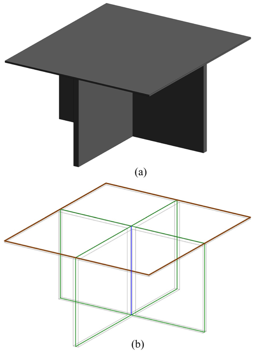
Plates and shear walls: (a) 3D entity and (b) representative planes.
FEM mesh development
The finite elements should be developed on the lines and planes. Along the lines, the beam element could be developed easily. The length of each element is a parameter of mesh development. On the other hand, the shell elements could be developed on the planes based on standard meshing tools. To form the whole structure as a system to resist the loads, the line meshes and plane meshes could not be separated from each other. They should be correctly connected according to the structural design of engineers. In this work, we propose the connection between plates and beams using common nodes. As shown in Figure 7, the plate of a floor is divided into small ones by the grid of beams. The small single plate is supported by the ambient beams. In the meshing tool, the plate of a single floor is developed as a whole one in the beginning. Then, it is partitioned using the lattice of beams as the partition lines. The seeds of mesh are scattered to the partition lines as well as the beams and the meshing for plate and beams is performed. The meshes within each single plate lattice are generated by the seeds along its sides. Finally, we merge the nodes on the beams and the partition lines of the plate. In this way, the deformations of beams and shells are compatible at the common nodes. The highlighted nodes shown in Figure 7 are the common nodes in the floor.
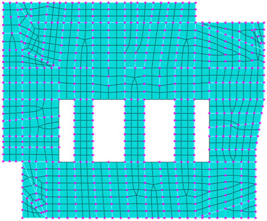
Common nodes of plate and beams.
According to the methodology developed in this section, the conversion between BIM and FEM includes four steps, as shown in Figure 8. Step 1 is the BIM model developed for the building project. In Step 2, the structural portion of the BIM is extracted and the geometry cleanup is performed. Step 3 is to develop the representative lines for beam–columns and the representative planes for slabs and walls. In the last step, the FEM mesh is developed with consideration of compatibility between beam elements and shell elements. The developed FEM model could be used in the further analysis and simulation of building structures.
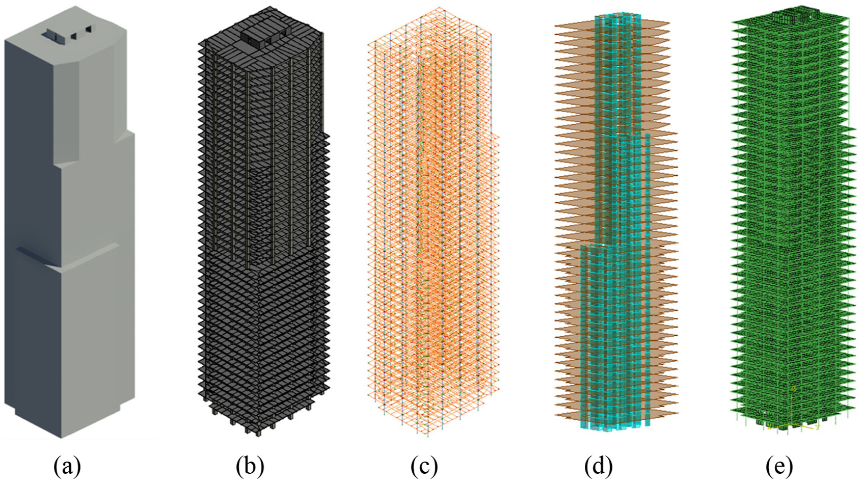
From BIM to FEM: (a) Step 1, (b) Step 2, (c) Step 3(a), (d) Step 3(b), and (e) Step 4.
Case study
Single high-rise building
Actually, the model shown in Figure 8 is developed based on a building project in Shanghai. The building has 47 floors and the total height is 214.5 m. The frame–core tube system (Figure 9) is adopted in the structural design. Most of the horizontal shear force and overturning moment are undertaken by the core tube, and the outer frame also supplies the overall bending stiffness. The outer frame and the core tube are linked by the coupling beams. The columns of the outer frame are designed as the steel tube–reinforced concrete (SRC) columns, and the beams are regular reinforced concrete (RC). The FE model shown in Figure 8(e) has 300,595 nodes, 88,012 beam elements, and 116,500 shell elements.
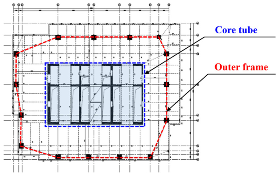
Structural layout of the bottom floor.
The concrete of beams and slabs is designed to be C35, for which the uniaxial compressive strength is 23.4 MPa and Young’s modulus is 30 GPa. The concrete of columns and shear walls is C60, for which the uniaxial compressive strength is 38.5 MPa and Young’s modulus is 38 GPa. Poisson’s ratio of concrete is considered to be 0.2 in the model. For the steel used in this project, the yield strength is 345 MPa, Young’s modulus is 200 GPa, and Poisson’s ratio is 0.3. To testify the FE model developed based on BIM, the analysis of natural periods is performed. The first, second, and third natural vibration modes are shown in Figure 10 with corresponding natural periods.
Natural modes: (a) T1 = 5.46 s, (b) T2 = 4.68 s, and (c) T3 = 4.25 s.
As we know, the structural system experiencing severe damage is rather unstable in the viewpoint of numerical simulation. Thus, the simulation of the building structure subjected extreme earthquakes often terminated by the illness of stiffness matrix for the implicit FEM. On the other hand, the explicit FEM is often used in this case to avoid the illness of stiffness matrix. More details of explicit FEM could be found in the work by Belytschko et al. (2013). Thus, the dynamic analysis of the building structures–subjected extreme earthquakes is performed. And the bi-directional earthquake is input on the bottom of the FE model. For each task, we just call the service of a single blade server, for which the computing resources are 16 cores and 16 GB RAM. The simulation for a single earthquake excitation takes approximately 3 h.
The acceleration time history record is shown in Figure 11. To simulate the extreme earthquake, the amplitude of the NS direction record is scaled to 1.2g. Actually, we performed the simulation for different peak ground accelerations (PGAs) and picked up the case with the most severe collapse pattern. To simulate the structural damage and failure, the damage plasticity model developed by Wu et al. (2006), Ren et al. (2015) and Wu (2018) is adopted for concrete. And the steel is reproduced by the standard plasticity model (Simo and Hughes, 1998).
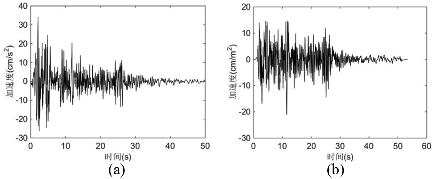
El-Centro record: (a) NS direction and (b) EW direction.
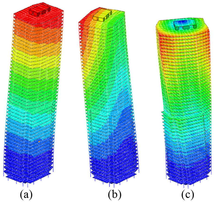
The numerical results for the building structures subjected to extreme earthquakes are shown in Figures 12 and 13. The contours in these two figures are tensile damage scalar (Ren et al., 2015), which reproduces the cracking and damage of concrete under tensile stresses. The red color means the concrete has been totally damaged and split by the tensile stress, while the blue color means the totally undamaged concrete without any cracking. At the moment of 2 s, damage initiates within the floors nearby the bottom of the building because of the high magnitudes of shear force and overturning moment nearby the bottom. At 3 s, the damage and deformation further accumulate on the bottom. In the meanwhile, some damages could be observed on the levels nearby the top. These damages are triggered by the high-order natural modes related to deformations on the top. Finally, at the time of 6 s, the core tube is seriously damaged and the slabs start to fall down. The overall collapse of the structure is observed.
Collapse of the building structure subjected to extreme earthquake: (a) 2 s, (b) 3 s, (c) 3.5 s, and (d) 4 s.
Collapse of the core tube subjected to the extreme earthquake: (a) 2 s, (b) 3 s, (c) 3.5 s, (d) 4 s, and (e) 6 s.
Building community
A building community located in Shanghai city is considered as an example. The layout of the community is shown in Figure 14, and the information of the individual buildings could be found in Table 1. As we can see, there are seven buildings in this community. Among them, building A is the highest one with the structural height of 219 m. Building B is also higher than 100 m. Buildings A and B are super high-rise buildings and others are high-rise buildings according to the design code of high-rise buildings in China (JGJ3-2015 (2015)). It is observed that the buildings are planned to be rather close to each other so that the functions of the buildings could support each other. Thus, in the design and analysis, the buildings should be considered as a whole community instead of individuals.
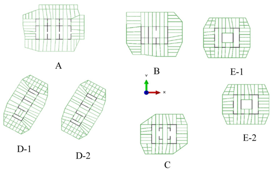
Layout of the building community.
Information of building structures in the community.
The BIM of the building community is developed, as shown in Figure 15(a). According to the techniques mentioned in section “Model export/conversion,” the beam–columns and slab–walls are extracted from the BIM, as shown in Figure 15 (b) and (c). The beam–columns are discretized by the beam elements. The slabs and walls are discretized by the shell elements. The connecting nodes between the beam elements and the shell elements are found and set to be common nodes. Finally, the FE mode is developed (Figure 15(d)) with 814,669 nodes, 339,881 beam elements, and 227,644 shell elements. Also, a rigid plate is implemented on the bottom of the whole community model as the holistic foundation with the uniform earthquake excitation input on the bottom.
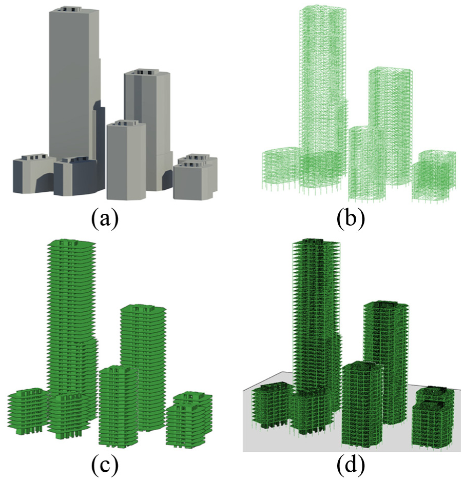
Models of the building community: (a) BIM, (b) beams and columns, (c) slabs and shear walls, and (d) FE model.
The El-Centro earthquake records (Figure 11) in two horizontal directions are adopted as the excitation. The amplitude of the acceleration record in NS direction is scaled to be 0.6g to simulate the extreme earthquake. The simulation of the building community is relatively difficult and computationally expensive. Thus, the value PGA is considered as 0.6g, which is smaller than the value of 1.2g in the simulation of single building. In this way, the simulation could be relatively easier and more stable. The damage plasticity model (Ren et al., 2015) is adopted to reproduce the damage and failure of concrete structures. In addition, the nonlinear behaviors of steel are modeled by the classic plasticity model (Simo and Hughes, 1998). Due to the burden of the FE model, the computing server is used to run the simulation. For each task, we just call the service of a single blade server, for which the computing resources are 16 cores and 16 GB RAM. The simulation for a single earthquake excitation takes approximately 15 h.
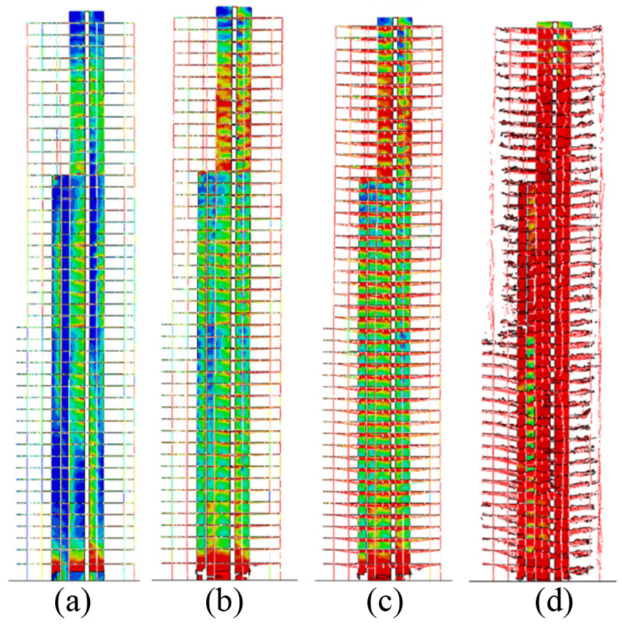
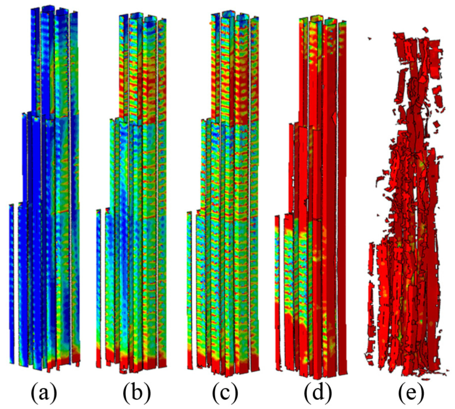
The contours of tensile damage for whole structures within the community are shown in Figure 16. The evolutions of damage in different structures are clearly shown. Thus, we conclude that the method developed in this article works. The damage patterns of the structures could be shown more clearly by the damage contours of the core tubes (Figure 17). The most serious damage among the five types of building structures is observed on building B. As for building B, two damage localization zones, for example, the bottom and the zone nearby the 10th floor, are observed. The damage localization nearby the bottom is induced by the bottom shear force and the damage nearby the 10th floor may be triggered by the high-order natural vibration mode. For the highest building type A, damage initiates and propagates nearby the transition zone for which the section of core tube changes. On the bottom, the core tube for the building type A is too strong to be damaged. For the building type B, for which the structural height is 145 m, the damage distribution is relatively uniform nearby the higher levels. For the lower building types D and E, the damage distribution is also relatively even along the height of the building, except for the bottom area.
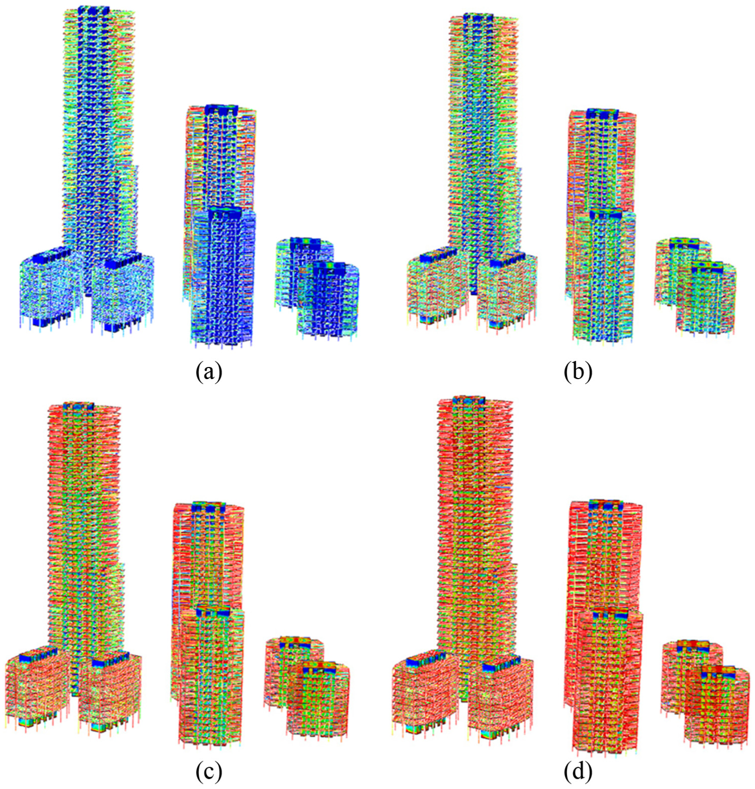
Contours of tensile damage at different moments: (a) 1 s, (b) 2 s, (c) 3 s, and (d) 4 s.
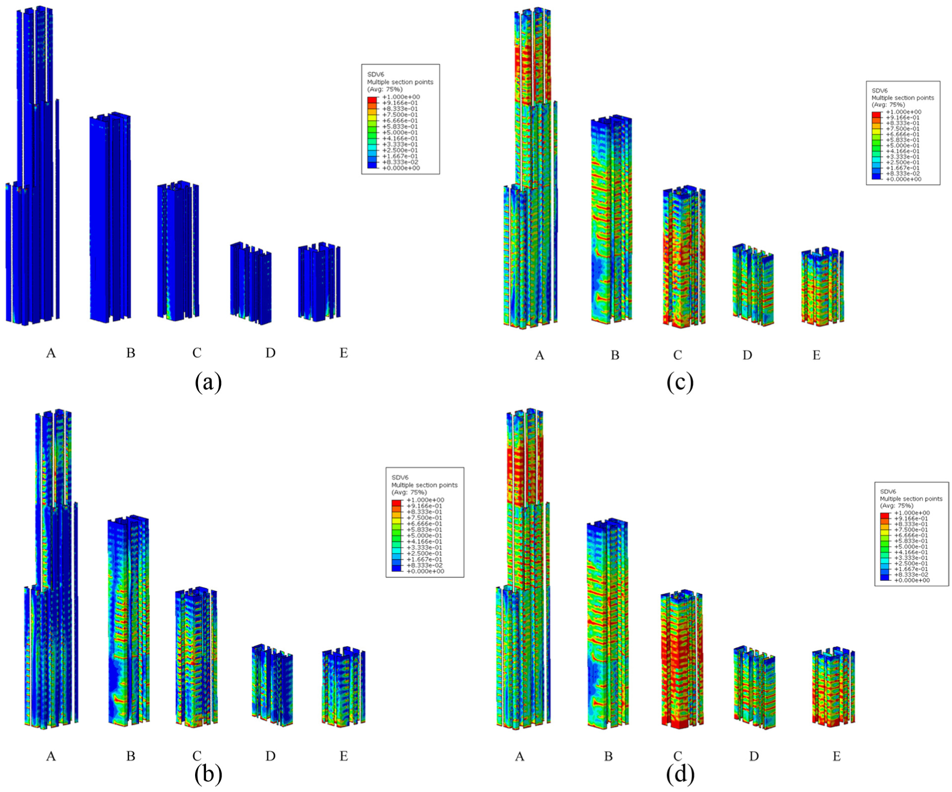
Tensile damage contours of core tubes at different moments: (a) 1 s, (b) 2 s, (c) 3 s, and (d) 4 s.
Conclusion
Based on the method developments and the numerical examples, several conclusions can be obtained as follows:
The proposed method could generate the structural model of building structures and building community based on BIM in an efficient way. Particular attentions should be paid to the model dimensionality reduction procedure and the connection of nodes.
The simulation of building community based on the refined FE model is feasible nowadays due to the advances of modern computer facilities and software. The damage patterns of different buildings in a community could be very different from each other.
As the first step, this work just shows the feasibility of the proposed method. The step forward of this study should be the function assessment of the individual buildings and the building community based on the simulated damage patterns.
The results generated by the refined FE model for the whole community is actually a pool of big data. How to make good use of the data and take full advantage of the simulation deserve further assessment.
Footnotes
Declaration of Conflicting Interests
The author(s) declared no potential conflicts of interest with respect to the research, authorship, and/or publication of this article.
Funding
The author(s) disclosed receipt of the following financial support for the research, authorship, and/or publication of this article: This study is supported by the financial supports from the National Natural Science Foundation of China (Grant Nos U1711264 and 51208374, 51678439).