
Abstract
To investigate the rotational behavior of concrete segmental joints with gaskets, bending tests are performed by detailed three-dimensional continuum numerical models for joints with and without gaskets. Based on the numerical results, an analytical model is proposed to analyze the rotational stiffness of the segmental joint and extend the simulation with related parametric studies. The bending tests reveal that the rotational behavior of the segmental joint with gaskets can be divided into four stages for both the sagging and hogging moment cases. The analytical results reveal that the sealing gasket has little influence on the joint rotational behavior, while the elastic gasket has a significant effect of reducing the joint rotational stiffness. Besides, the rotational behavior of the joint with gaskets is affected by the axial force and the bolt pre-tightening force to a certain degree. The proposed analytical model allows the effect of the properties of bolts and various gaskets, the concrete contact force, the geometry of the joint section, and the subjected loads to be taken into consideration. The analytical results are well consistent with the numerical results, and the analytical model can be adopted for simulation of the segmental joint with various gaskets.
Introduction
The segmental joint of the shield tunnel lining comprises connecting the segments with bolts and some packing materials (e.g. sealing gasket and elastic gasket). It is one of the most important structures for the concrete segmental lining. Deformation and stress transmission of the segmental joint can directly affect the overall performance of the shield tunnel lining. Since the segmental joint can directly sustain bending moments, axial forces, and shear forces, this rigidity characteristic of the joint can be depicted by three stiffnesses: rotational stiffness, axial stiffness, and shear stiffness (Ding et al., 2004; Do et al., 2014; Nematollahi et al., 2018). Some literatures reveal that the axial and shear stiffnesses have a negligible impact on the segmental lining behavior, while the segmental lining behavior is impacted to a great extent by the rotational stiffness, which is one of the most important parameters in the design and operation of the shield tunnel (Do et al., 2013; Feng et al., 2019; ITA, 2000).
At present, a large number of literatures report the rotational behavior of the segmental joint. The bending test is one of the most effective methods to investigate the rotational behavior of the joint. According to the test results, the joint deformation subjected to the bending moment can be observed directly, and the range of the joint rotational stiffness can be estimated from the relationship between the joint rotational angle and the bending moment (Blom, 2002; de Waal, 2000; Liu et al., 2018; Teachavorasinskun and Chub-uppakarn, 2010; Yan et al., 2016). Besides, the rotational stiffness of the joint can also be obtained by analytical solution. For this approach, it is mainly based on the equilibrium equations of the force and moment at the joint. The dominating deformation of the segmental joint is represented on the concrete compressive strain and the bolt tensile strain, and the concrete stress distribution is obtained by equations of the force and geometry relationship under the assumption of triangular, rectangular, or parabolic distribution of the stress (Do et al., 2018; Koyama, 2000; Li et al., 2015; Shen et al., 2015; Tvede-Jensen et al., 2017). Both the bending tests and analytical solutions indicate that the rotational stiffness is larger when the joint is subjected to a sagging moment than when it is subjected to a hogging bending moment; the rotational stiffness is affected by various factors such as the bending moment, the axial force, and the bolt pre-tightening force.
One of the significant differences in the segmental joint structures is whether the various gaskets are attached to the segmental joints. Since the gasket has a significant effect on water sealing, planeness improvement, and stress transmission, it has become an important component of the segmental joint (Cho et al., 2017; Ding et al., 2017; Luciani and Peila, 2019). However, in previous researches, little attention was paid to the stress transmission of the gasket, especially the elastic gasket. Bending tests are conducted mainly for the joint without gaskets. Existing analytical models have not simultaneously considered the properties of bolts and gaskets, the concrete contact force, the geometry of the joint section, and the subjected loads for the joint with various gaskets. The effect of the gasket on the rotational behavior of the segmental joint has not been fully clarified.
In this study, to reveal the rotational behavior of the segmental joint with gaskets, bending tests are performed by three-dimensional (3D) numerical models to compare the rotational behaviors between the joint with gaskets and the joint without gaskets. Besides, an analytical model is proposed for the segmental joint with gaskets to obtain the joint rotational stiffness. Based on the analytical model, the influences of the sealing gasket, elastic gasket, axial force, and bolt pre-tightening force on the rotational behavior of the joint is investigated.
Bending test of the segmental joint
Outline of the test
A concrete segmental joint with gaskets is presented in Figure 1. The concrete type of the segment is C50. The segment width and thickness are 1.2 and 0.35 m, respectively. The segmental joint is connected by two M32 straight bolts, one sealing gasket, and two elastic gaskets. The thickness of the elastic gasket is 2 mm. The pre-tightening force of each bolt is 100 kN, and the yield strength of the bolt is 640 MPa. The details of the joint without gaskets and the joint with gaskets are the same, while the former has no elastic gasket.
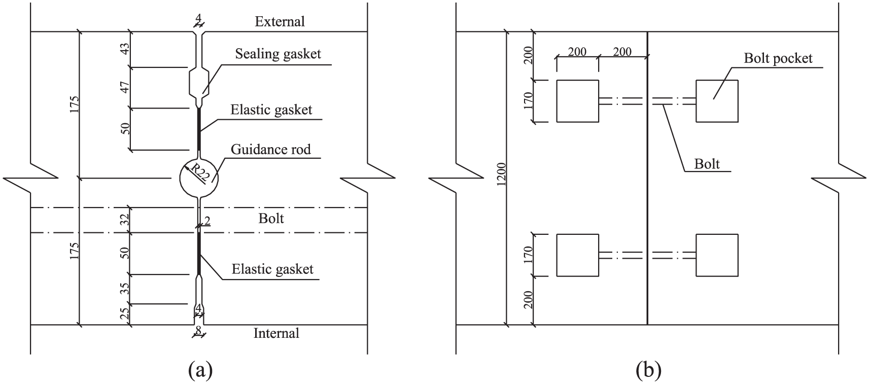
Details of the segmental joint with gaskets (mm). (a) Front view. (b) Bottom view.
Some researches reveal that a straight segment instead of a curved segment can be used to simplify the bending test and related calculations (Ahn, 2011; Avanaki et al., 2018; Gong et al., 2017). As shown in Figure 2, bending test is conducted using two connected straight segments. A fixed support and a roller support are positioned on the left and right ends of the model, respectively. The axial forces and the bending moments are implemented by the horizontal loads (N) and the vertical loads (FM), respectively.
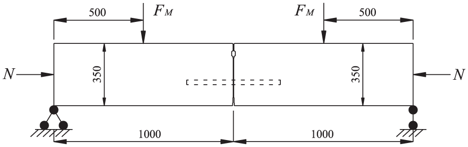
Bending test of the segmental joint (mm).
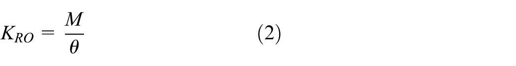
As shown in Figure 3, the joint rotation angle (θ) can be calculated using equation (1). According to equation (2), the rotational stiffness (KRO) of the joint can be obtained by the slope of the joint rotation angle (θ) versus bending moment (M).
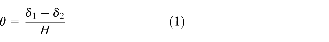
where δ1 is the averaged deformation at the opening edge; δ2 is the averaged deformation at the compression edge; and H is the thickness of the segment.

Schematic view of the joint rotation angle.
Material models
Concrete
The multilinear isotropic hardening stress–strain relationship of the concrete is obtained by the code for design of concrete structures in China (GB 50010, 2010), and the von Mises yielding criterion is considered as


where σc is the compressive stress of concrete at any strain εc; ε0 is the strain corresponding to the compressive strength (
Bolt
The stress–strain relationship of the bolt is idealized to be bilinear kinematic hardening with a post-yield strain hardening of 1%
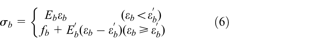
where σb is the stress at any strain εb and
Gasket
The constitutive models of the sealing gasket and elastic gasket are obtained by the compressive tests (Zhong et al., 2006), which can be expressed as


where Fs is the compressive force on the sealing gasket per meter (N); Δs is the compressive deformation of the sealing gasket (mm); and σe is the compressive stress of the elastic gasket at any strain εe (MPa).
3D numerical model
As shown in Figure 4, detailed 3D continuum numerical models of the joint with gaskets and the joint without gaskets are established using the 3D finite element analysis software ANSYS to perform the bending tests. Eight-node 3D solid elements (SOLID65) are used for the concrete. Eight-node 3D solid elements (SOLID45) are used for the bolt and the sealing gasket. Eight-node 3D interface elements (INTER195) are used for the elastic gasket. The interactions between the bolt and the segment consist of two parts: (1) the interaction between the bolt and the bolt hole and (2) the interaction between the nut and the segment. The interactions between the segments also consist of two parts: (1) the interaction between the sealing gasket and the segment and (2) the interaction between the surfaces of the segment edge. These interactions are simulated by “face-to-face” contact elements (TARGE170 and CONTA174) which can simulate cold interface conditions transmitting only compression force in the normal direction and shear force in the tangential direction (Sun et al., 2019). In common conditions, the friction coefficient of concrete is 0.3–0.4. In this study, an average value of 0.35 was selected.

3D numerical model of the segmental joint with gaskets. (a) Segment model. (b) Joint model.
Loading
The process of the loading is divided into three steps. Step 1: the pre-tightening force (100 kN) is applied on each bolt. Step 2: the horizontal load is applied to 1000 kN. Step 3: the vertical load is applied at a rate of 20 kN per substep until the joint is damaged.
Numerical test results
Sagging moment case
With increase in the sagging moment, deformation of the joint and stress of the concrete are investigated. As shown in Figures 5(a), 6(a), and 7(a), the process of joint deformation can be divided into four stages. In Stage 1, the joint is almost not opening and the concrete connected to the upper and lower elastic gaskets are obviously compressed. In Stage 2, the joint opening becomes obvious. The neutral axis of the cross section has moved above the lower elastic gasket, which cannot contribute to the joint behavior in this stage. Therefore, the concrete only connected to the upper elastic gasket is compressed obviously. In Stage 3, the concrete at the external edge is compressed and becomes an important bearing structure for the joint. The additional concrete contact force has effectively reduced the rate of the joint opening. In Stage 4, the neutral axis of the cross section has moved above the upper elastic gasket which cannot contribute to the joint behavior in this stage, and the concrete only at the external edge is compressed obviously. With further increase in the sagging moment, the concrete at the external edge is compressed to failure, and the yield region expands from the contact points to the inside rapidly.

Schematic view of the joint deformation. (a) Sagging moment case. (b) Hogging moment case.
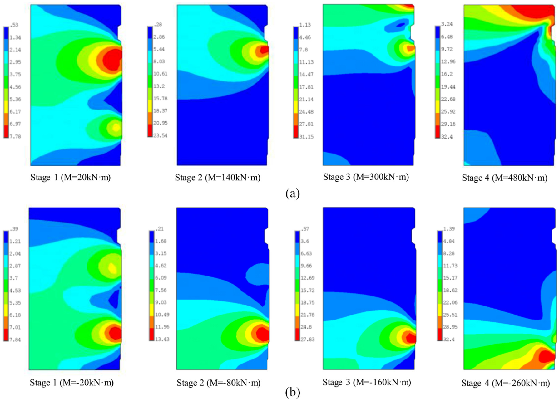
Equivalent stresses of the joint concrete (MPa). (a) Sagging moment case. (b) Hogging moment case.

Joint rotation angle versus bending moment. (a) Sagging moment case. (b) Hogging moment case.
Comparison of the two curves in Figure 7(a) shows that the gaskets have a significant influence on the rotational stiffness of the segmental joint for the sagging moment case. When the joint is subjected to the same sagging moment, the rotation angle of the joint with gaskets is obviously larger than that without gaskets. According to the slopes of the two curves, in Stages 1 and 2, the rotational stiffness of the joint with gaskets is obviously smaller than that without gaskets. This is because the concrete at the segment edge is not compressed in these two stages. For the joint with gaskets, the gaskets become important bearing structures for the joint in these stages. Therefore, the effect of the gaskets on the joint rotational behavior is more significant, which leads to obvious decrease in the joint rotational stiffness. However, the two curves tend to be parallel in Stages 3 and 4. This is because that the compressed segment edge and the tensioned bolt become the most important bearing structures, while the gasket gradually fails to contribute to the joint behavior in these two stages, which leads the stress state of the joint with gaskets to be similar to that of the joint without gaskets. Overall, the gaskets have a significant effect of reducing the joint rotational stiffness.
Hogging moment case
As shown in Figures 5(b), 6(b), and 7(b), the development of the joint opening for the hogging moment case can also be divided into four stages. In Stage 1, all the gaskets are compressed. The joint deformation and the concrete stress distribution are almost the same as those in Stage 1 for the sagging moment case (Figures 5(a) and 6(a)). In Stage 2, the neutral axis of the cross section has moved below the sealing gasket. Since the compression stiffness of the sealing gasket is much small, the rate of the joint opening almost does not change, but the compression region area of the concrete connected to the upper elastic gasket tends to be decreased rapidly. In Stage 3, the neutral axis of the cross section has moved below the upper elastic gasket, which does not contribute to the joint behavior, and only the concrete connected to the lower elastic gasket is compressed severely. In this stage, the rate of the joint opening is increased obviously. In Stage 4, the concrete at the internal edge becomes compressed, which can effectively reduce the rate of the joint opening. With further increase of the hogging moment, the concrete at the external edge is compressed to failure ultimately, and the yield region expands from the contact points to the inside rapidly.
It is obvious that, when the joint is subjected to the same hogging moment, the rotation angle of the joint with gaskets is larger than that without gaskets (Figure 7(b)). According to the slopes of the two curves, the rotational stiffness of the joint with gaskets is smaller than that without gaskets, especially in Stages 1–3. In Stage 4, the two curves tend to be parallel. Similar to the sagging moment case, the gaskets have a significant effect of reducing the joint rotational stiffness for the hogging moment case.
Analytical model for the joint with gaskets
Sagging moment case
According the numerical test results, the rotational behavior of the joint can be divided into four stages for the sagging moment case. For the analytical model, each stage corresponding to the test results is determined by the height of the joint opening region (ho) and the relative displacement between the two segments at the external edge (Δe).
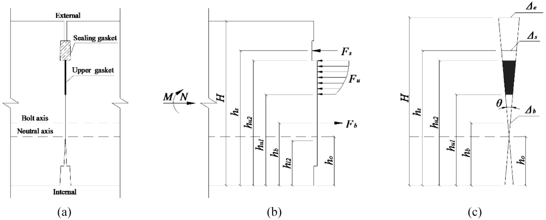
Stage 1: S-U-B-L stress state
When
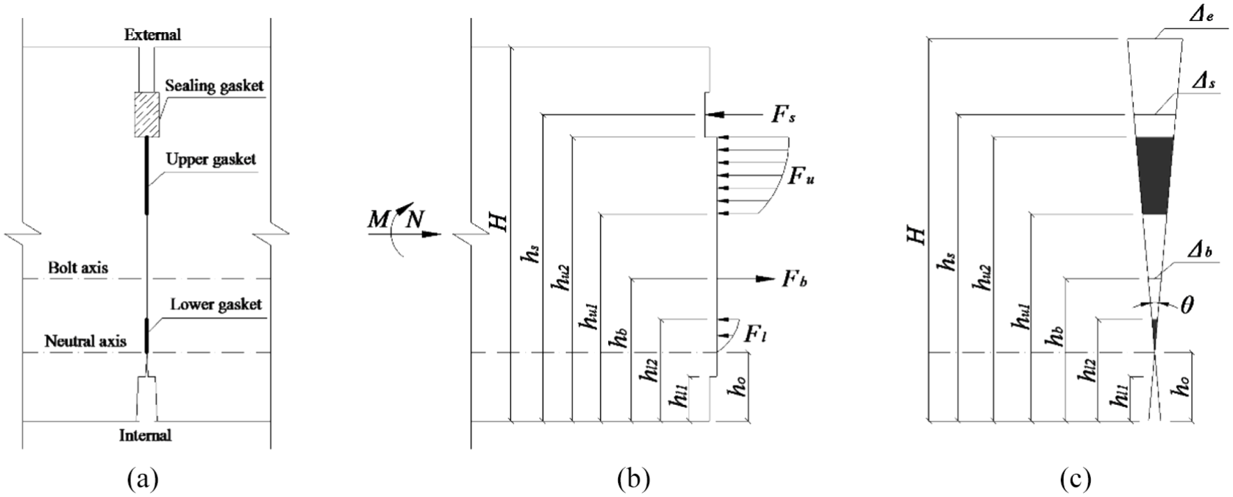
S-U-B-L stress state for the sagging moment case. (a) Joint deformation. (b) Equilibrium condition. (c) Deformation distribution.
The force and moment equilibrium equations can be expressed as


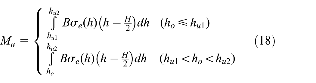
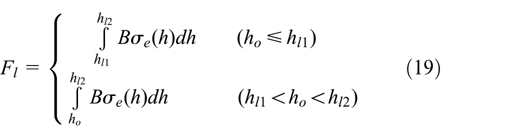
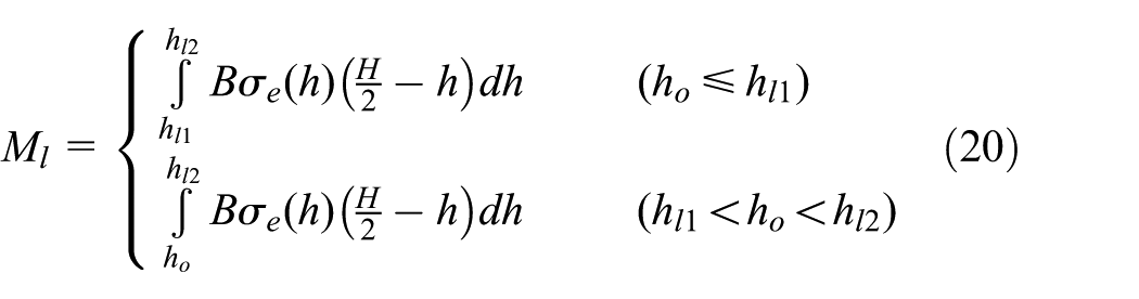
where N is the axial force; Fs is the force of the sealing gasket; Fu is the equivalent force of the upper gasket; n is the number of the bolts; Fb is the force of the bolt; Fl is the equivalent force of the lower gasket; and M, Mu, and Ml are the moments induced by the force N, Fu, and Fl, respectively.
According to the deformation distribution in Figure 8(c), the following equations can be obtained


where
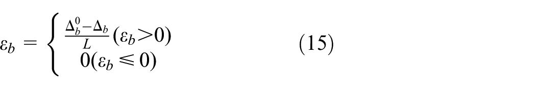
Fs can be obtained by equations (7) and (12). Fb can be obtained by equation (6) and equations (13) to (15).
For the elastic gasket, the strain can be calculated as
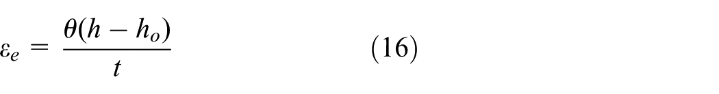
where h is the height from the opening edge to the calculated position; and t is the thickness of the gasket. According to equations (8) and (16), the following can be obtained
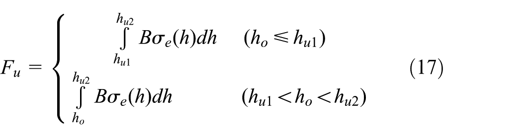
where B is the width of the segment.
According to the above equations, ho and θ can be calculated, and the rotational stiffness of the joint can be obtained by the slope of the joint rotation angle versus bending moment.
Stage 2: S-U-B stress state
When
S-U-B stress state for the sagging moment case. (a) Joint deformation. (b) Equilibrium condition. (c) Deformation distribution.
The force and moment equilibrium equations can be expressed as


The calculations of Fs, Fu, Fb and Mu are as the same as those in equations (9) and (10).
Stage 3: E-S-U-B stress state
When

E-S-U-B stress state for the sagging moment case. (a) Joint deformation. (b) Equilibrium condition. (c) Deformation distribution.
The force and moment equilibrium equations can be expressed as


The calculations of Fs, Fu, Fb and Mu are as the same as those in equations (9) and (10).
For the concrete at the segment external edge, the concrete strain can be calculated as
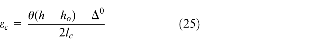

where
Stage 4: E-S-B stress state
When

E-S-B stress state for the sagging moment case. (a) Joint deformation. (b) Equilibrium condition. (c) Deformation distribution.
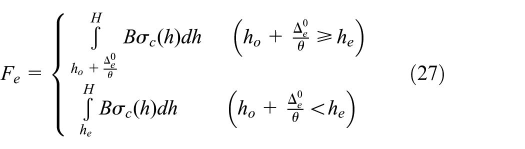
The force and moment equilibrium equations can be expressed as


The calculations of Fs and Fb are as the same as those in equations (9) and (10). Fe and Me can be calculated by equations (27) and (28), respectively.
Hogging moment case
According to the numerical test results, the rotational behavior of the joint can also be divided into four stages for the hogging moment case. For the analytical model, each stage corresponding to the test results is determined by the height of the joint opening region (ho) and the relative displacement between the two segments at the internal edge
Stage 1: S-U-B-L stress state
When

S-U-B-L stress state for the hogging moment case. (a) Joint deformation. (b) Equilibrium condition. (c) Deformation distribution.
The force and moment equilibrium equations can be expressed as


According to the deformation distribution in Figure 12(c), the following equations can be obtained


Fs can be obtained by equations (7) and (34) and Fb can be obtained by equations (6), (14), (15) and (35).
For the elastic gasket, the following equations can be obtained


Stage 2: U-B-L stress state
When

U-B-L stress state for the hogging moment case. (a) Joint deformation. (b) Equilibrium condition. (c) Deformation distribution.
The force and moment equilibrium equations can be expressed as


The calculations of Fu, Fb, Fl, Mu, and Ml are as the same as those in equations (31) and (32).
Stage 3: B-L stress state
When
B-L stress state for the hogging moment case. (a) Joint deformation. (b) Equilibrium condition. (c) Deformation distribution.
The force and moment equilibrium equations can be expressed as


The calculations of Fb, Fl and Ml are as the same as those in equations (31) and (32).
Stage 4: B-L-I stress state
When
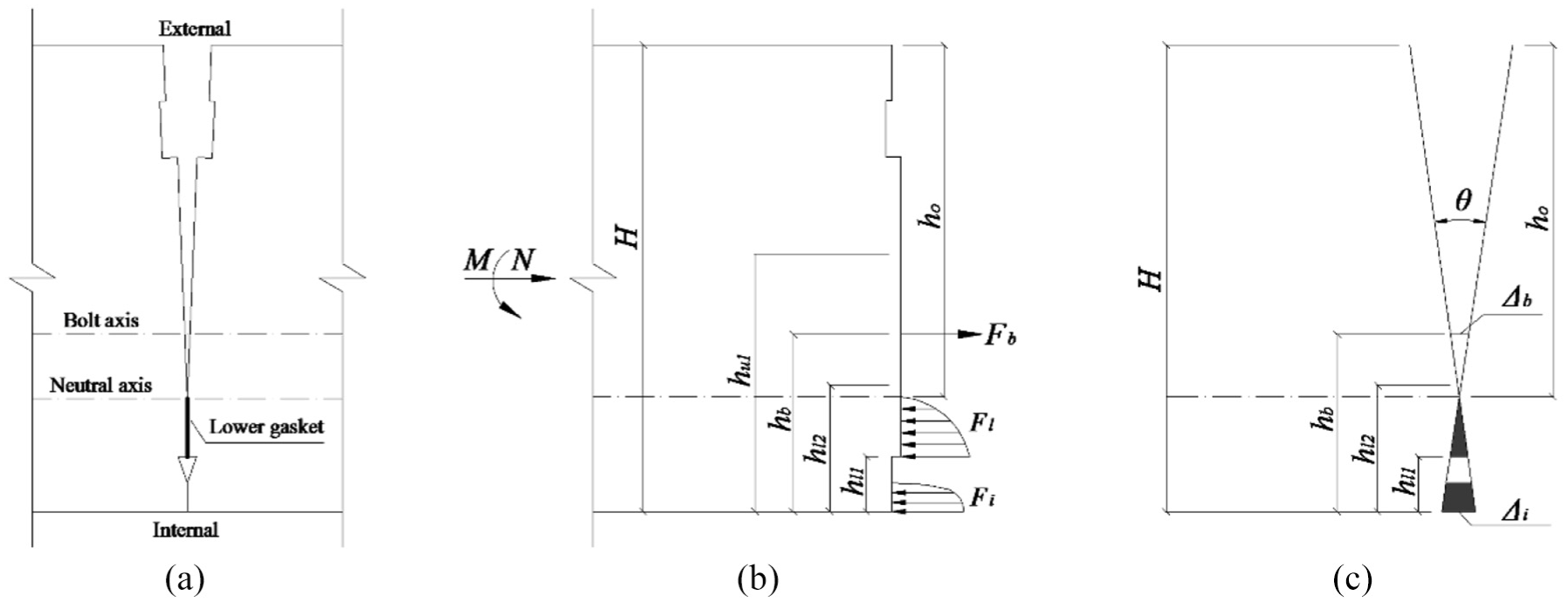
B-L-I stress state for the hogging moment case. (a) Joint deformation. (b) Equilibrium condition. (c) Deformation distribution.
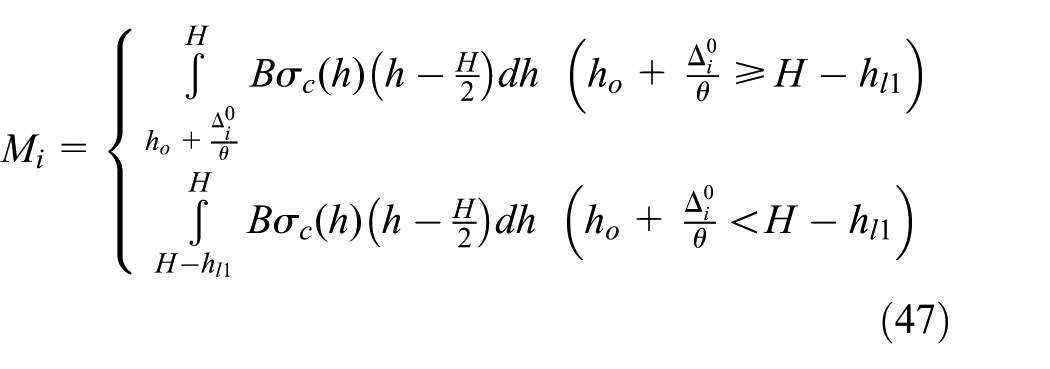
The force and moment equilibrium equations can be expressed as


The calculations of Fb, and Fl are as the same as those in equations (31) and (32). For the concrete at the segment internal edge, the concrete stress

Comparison between the numerical model and the analytical model
The joint rotation angles with different bending moments are calculated by the analytical model. The joint rotation angle versus sagging moment and the joint rotation angle versus hogging moment are presented in Figure 16(a) and (b), respectively. The numerical results of the bending test are also presented in Figures 16 for comparison.

Comparison between numerical results and analytical results. (a) Sagging moment case. (b) Hogging moment case.
As shown in Figures 16, both the joint rotation angle versus sagging moment and the joint rotation angle versus hogging moment are characterized by four stages. The analytical results are well consistent with the numerical results, especially in the first three stages. As shown in Figures 5 and 6, with increase in the sagging moment or the hogging moment, the concrete at the external edge or at the internal edge is compressed to yield, and the concrete becomes the most important bearing structure in Stage 4 for both the cases. However, compared with the 3D continuum model, the 3D effect of the concrete stress condition cannot be well considered in the analytical model, which may lead to the rates of the joint opening of the analytical model a little quicker than those of the numerical model in Stage 4.
Parametric study of segmental joint behavior
Influence of the sealing gasket
Based on the proposed analytical model, the influence of the sealing gasket on the rotational behavior of the joint is investigated. For the same bending moment, the rotation angle of the joint with sealing gasket and the rotation angle of the joint without sealing gasket are almost the same, and the differences in the joint rotation angle between the two joints are within 5%. The results indicate that the sealing gasket has little influence on the joint rotational behavior, since it is much softer than the elastic gasket, blot, and concrete. Therefore, according to section “Numerical test results,” it is the elastic gasket which has a significant effect of reducing the joint rotational stiffness, and the gasket below refers to the elastic gasket.
Influence of the gasket hardness
The influence of the elastic gasket hardness on the rotational behavior of the joint is investigated. The curves of joint rotation angle versus sagging moment and hogging moment with different gasket hardness of soft

Influence of the gasket hardness. (a) Sagging moment case. (b) Hogging moment case.
As shown in Figures 17, the elastic gasket hardness has a significant influence on the behavior of the segmental joint for both the sagging and hogging moment cases. As shown in Figures 5 and 6, the concrete at the segment external edge or internal edge is compressed in Stage 3 for the sagging moment case and in Stage 4 for the hogging moment case. It is obvious that the harder the gasket, the later the concrete at the segment edge begins to be compressed. According to the slopes of the curves, it can be seen that the decrease in gasket hardness generally results in decreases in the joint rotational stiffnesses for both the cases.
Influence of the gasket thickness
The influence of the elastic gasket thickness (t) on the rotational behavior of the joint is investigated. The curves of joint rotation angle versus sagging and hogging moments with different gasket thicknesses of 1, 2 and 3 mm are presented in Figure 18(a) and (b), respectively.
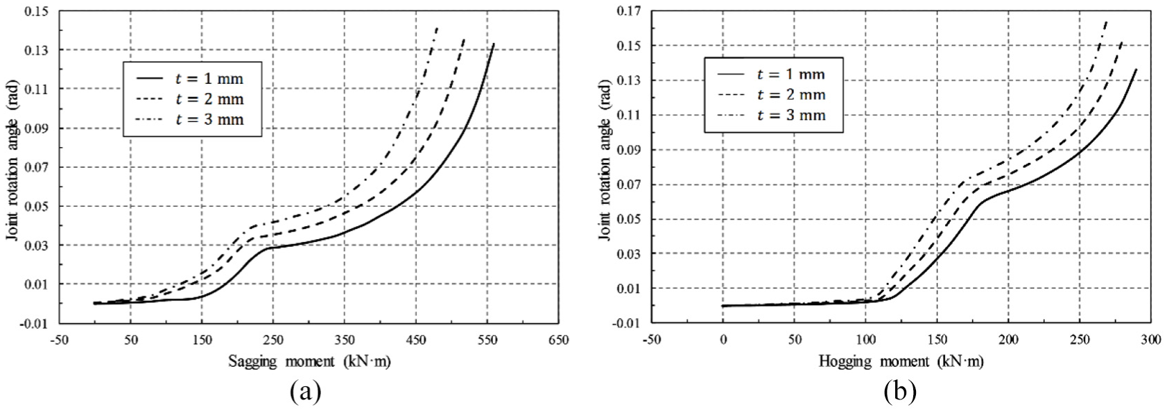
Influence of the gasket thickness. (a) Sagging moment case. (b) Hogging moment case.
Since the gasket thickness directly impacts the gasket strain and the initial gap between the concrete at the segment edges, the gasket thickness has a significant influence on all stages of the segmental joint behavior for both the sagging and hogging moment cases. As shown in Figure 18, when the joint is subjected to the same sagging moment or the same hogging moment, the larger the gasket thickness, the larger the joint rotation angle. According to the slopes of the curves, it can be seen that the increase in gasket thickness generally results in decreases in the joint rotational stiffnesses for both the cases.
Influence of the axial force
The influence of the axial force (N) on the rotational behavior of the joint is investigated. The curves of joint rotation angle versus sagging and hogging moments with different axial loads of 500, 1000, and 1500 kN are presented in Figure 19(a) and (b), respectively.

Influence of the axial force. (a) Sagging moment case. (b) Hogging moment case.
As shown in Figure 19, the axial force has a significant influence on all stages of the segmental joint behavior for both the sagging and hogging moment cases. When the joint is subjected to the same sagging moment or the same hogging moment, the larger the axial load, the smaller the joint rotation angle. According to the slopes of the curves, it can be seen that the joint rotational stiffnesses increase with increase in the axial load.
Influence of the bolt pre-tightening force
The influence of the bolt pre-tightening force (F0) on the rotational behavior of the joint is investigated. The curves of joint rotation angle versus sagging moment and hogging moment with different pre-tightening forces of 0, 50, 100, and 150 kN are presented in Figure 20(a) and (b), respectively.

Influence of the bolt pre-tightening force. (a) Sagging moment case. (b) Hogging moment case.
According to Figure 5 and the calculation results, in Stage 2 for the sagging moment case and in Stage 4 for the hogging moment case, the bolt tensile strain caused by the bending moment begins to increase rapidly, and the bolt becomes an important bearing structure. Therefore, the bolt pre-tightening force affects the rotational behavior of the segmental joint mainly in the two stages. As shown in Figure 20, when the joint is subjected to the same bending moment, with increase in the bolt pre-tightening force, the joint rotation angle is slightly decreased.
Conclusion
Numerical bending tests are performed for the joint with gasket and the joint without gasket, and an analytical model is proposed to analyze the rotational stiffness of the segmental joint. Based on the results of the numerical simulation and analytical solution, the full rotational behavior of the segmental joint with various gaskets is investigated, and the following conclusions can be drawn:
According to the height of the joint opening region and the relative displacement between the two segments at the edge, the rotational behavior of the segmental joint with gaskets can be divided into four stages for both the sagging and hogging moment cases, showing a very complex nonlinear characteristic of the relationship between the joint rotational angle and the bending moment.
The proposed analytical model of the segmental joint can simultaneously consider the properties of the bolts and the various gaskets, the concrete contact force, the geometry of the joint section, and the subjected loads. It is a simplified and effective method to analyze the rotational behavior and calculate the rotational stiffness of the segmental joint with gaskets. It is noteworthy that, for the other segmental joints with different structure details, the analytical model can still be used, but the stages and the corresponding stress states may not be exactly the same as those in this study.
The sealing gasket has little influence on the joint rotational behavior, while the elastic gasket has a significant effect of reducing the joint rotational stiffness for both the sagging and hogging moment cases. Since the joint rotational stiffness can be further decreased with decrease in the elastic gasket hardness or increase in the elastic gasket thickness, too soft or too thick gaskets should not be used for the segmental joint.
The bearing capacity of the segmental joint is obviously affected by the axial force for both the sagging and hogging moment cases. With increase in the axial load, the joint rotation angle is decreased and the joint rotational stiffness is increased. Besides, the bolt pre-tightening force has a slight influence on the rotational behavior of the segmental joint. With increase in the bolt pre-tightening force, the joint rotation angle is generally decreased mainly in the stages when the bolt tensile strain begins to be increased rapidly.
Footnotes
Declaration of Conflicting Interests
The author(s) declared no potential conflicts of interest with respect to the research, authorship, and/or publication of this article.
Funding
The author(s) disclosed receipt of the following financial support for the research, authorship, and/or publication of this article: The authors appreciate the support of the Open Research Fund Program of State Key Laboratory of Hydroscience and Engineering (Grant No.: sklhse-2018 -C-01) and the Hubei Province Natural Science Foundation of China (Grant No.: 2017CFB667).