



Abstract
Adjacent precast prestressed concrete box beam bridges have been widely utilized for decades and have shown satisfactory performance. However, significant issues regarding to the longitudinal shear key cracking have been noted by bridge maintenance personnel. The cracks are typically initiated at beam-shear key interfaces due to shrinkage and temperature and propagate due to applied load. Recently, ultra-high-performance concrete (UHPC) was employed in the shear keys with the anticipation to prevent joint cracking. Although the field-collected data at early age from bridge utilizing UHPC shear keys indicated promising performance, the results only reflected the early age joint behavior at locations which were instrumented during the field test. In the current study, a 3D finite element (FE) model was developed to calculate the early age stresses due to shrinkage and temperature. The results indicated that the UHPC material associated with a specific shear key configuration created a “self-locked” phenomenon that generated compression on the upper level shear key. The early age tensile stress during the first couple of days near the end of the joint was relatively small compared to the tensile strength of UHPC material. Although the interface had sufficient capacity to resist the early age stresses, it is still a critical component and needs to be designed with sufficient capacity.
Introduction
Adjacent precast prestressed concrete box beam bridges have been widely utilized for decades and show satisfactory performance. In these bridges, the box beams are placed next to each other on top of the substructure and the shear keys between the beams are filled with cement-based grouts to create a longitudinal joint. Sometimes transverse post-tensioning is applied to enhance the transverse continuity of the bridge. Partial or full depth shear keys are usually used with a narrow width of 19.1 mm–38.1 mm (0.75 in.–1.5 in.) between the adjacent beams. Typically, the shear keys between beams are filled with cement-based grouts. These shear keys are design to provide enough capacity to transfer the transverse moment and shear (Attanayake and Aktan, 2014; El-Remaily et al., 1996; Hanna et al., 2011; Russell, 2009; Semendary Ali et al., 2019a).
Adjacent box beam bridges have suffered from longitudinal shear key cracking which causes reflective cracks in overlays (Russell, 2009). As a result, chlorides and water may enter shear keys through cracks and accelerate the corrosion of the mild and pre-stressing steel. Consequently, the cracking issue has led to significant maintenance costs and reduce bridge service life (Russell, 2009). Past studies indicated that low bond strength at the beam-key interface are the main causes of the cracks (Attanayake and Aktan, 2014). The shrinkage of grout material and the effect of daily and/or seasonal temperature are the main reasons for the initiation of the cracks while the applied load propagates the cracks (Hansen et al., 2012; Miller et al., 1999). The longitudinal cracks might also develop as a result of non-uniform distribution of transverse post-tensioning by inducing transverse tensile stress (Grace et al., 2012).
The superior properties of ultra-high-performance concrete (UHPC) have led to many successful applications such as using UHPC as a connection material in bridge structures. Research work conducted on UHPC began more than 20 years ago, and the first structural application was in the late 1990s. The first field application of UHPC in the United States highway infrastructure was in 2006. Since that time, a significant amount of research has been conducted to explore the application of UHPC in different structural components (Russell and Graybeal, 2013). For example, research has been conducted to investigate the longitudinal UHPC closure pour connection in prefabricated deck systems (Aaleti et al., 2013; Yuan and Graybeal, 2016). Shafieifar (2018) has designed UHPC connections between pier columns and cap beams for seismic and non-seismic regions. Research teams have also used UHPC in the longitudinal connections between adjacent box beams (Perry and Seibert, 2012; Yuan and Graybeal, 2016). It has been reported that UHPC provide a barrier to the corrosion due to the low permeability which can extend the service life of the structures that repaired with UHPC (Farzad et al., 2018; 2019a; 2020). Therefore, the UHPC is a good candidate for shear key in box beam bridges that usually experienced durability issues due to longitudinal cracking. Yuan and Graybeal (2016) investigated the performance of partial and full depth shear keys filled with UHPC in the longitudinal connections between two side-by-side full scale box beams. The shear key utilized staggered shear reinforcement extending from the adjacent beams to create lap spliced reinforcement across the joint. The joint was evaluated through daily temperature changes at early age and four-point cyclic bending tests. The results indicated that the UHPC joint performed well. The inspection results indicated that no cracks or interface debonding were induced by the temperature changes or applied load.
The field performance of partial depth reinforced UHPC shear key in a box beam bridge was explored during the first 7 days after UHPC casting by Semendary Ali et al. (2019a). The transverse dowels played a significant role by carrying the stresses in the shear keys before the joint material had gained sufficient strength. Although joint behavior was evaluated by the field-collected data which showed good performance at early age, there was no comprehensive investigation on the stress distribution in the UHPC filled joint. The measured data reflected only the total strain (including thermal/shrinkage strain) at the instrumentation location. Furthermore, instrumentation was not used to investigate possible interfacial failure at an early age, but visual inspection did not reveal any cracking.
Research work has not been conducted on the modeling of early age UHPC connection behavior. However, research has been performed on the modeling of connections filled with other cement-based materials. Shi et al. (2019) explored the joint behavior at early age between side-by-side box beams by performing heat transfer analyses and coupled thermal-stress analyses utilizing FE modeling software. A FE method was also used to investigate the early age shear key performance between precast concrete box girders by considering the time-dependent material properties under both shrinkage and temperature effect (Liu and Phares, 2019a). The stress in the shear key was compared with the allowable time-dependent tensile strength to determine crack initiation. The results indicated similar stress distributions before cracking for the model with and without the interface contact element. Therefore, the crack element was not considered in the modeling since no cracking was observed during the early age of the joint material. The authors concluded that the shear key experienced tensile stress near the edges. A novel 165 mm (6.5 in.) wide joint incorporating shrinkage compensating concrete as the grout material with transverse reinforcing steel was investigated by Liu and Phares (Liu and Phares, 2019b; Liu et al., 2020) using the model developed by Liu and Phares (2019a). The early age shear key performance was successfully predicted. The results indicated that the reinforced shear key exhibited a satisfactory performance with no early age cracking.
Although the early age cracking has been frequently observed in box beam bridges, a few studies were numerically investigated the early age stresses in box beam bridges with non-shrink grout shear keys. Meanwhile, no numerical study has been conducted on early age stresses of the box beam bridges with UHPC shear keys. UHPC has relatively high autogenous shrinkage and coefficient of thermal expansions which create high stresses at the early age. In the current study, the early age performance of a reinforced UHPC shear key is explored using FE modeling subjected to shrinkage and thermal change. To achieve this objective, the early age time-dependent material properties of UHPC were identified and incorporated into the model. The full scale bridge model was established based on the monitored bridge in Semendary Ali et al. (2019a) and validated against the field-collected data. The time-dependent stress development in the UHPC shear key and at the beam-key interface was estimated using the FE model.
Ultra-high-performance concrete material properties
In order to correctly predict the stress development in the UHPC joint, an accurate capture of the early age material properties is required. Fortunately, previous studies were found that provided detailed information on various early age material properties. Graybeal (2006) documented comprehensive material tests investigating the material characters of a commercially available UHPC. Various material properties of the UHPC were studied including the tensile strength, Young’s Modulus, compressive strength, shrinkage, and thermal expansion coefficient. The UHPC exhibited compressive and tensile strengths of about 193 MPa (28 ksi) and 9.0 MPa (1.3 ksi), respectively, and a modulus of elasticity of 52.4 GPa (7600 ksi). Equation (1) was developed to predict tensile strength if compressive strength is known. In this equation, the multiplier (


Yoo et al. (2013) investigated the time-dependent modulus of elasticity and tensile strength of UHPC through laboratory testing. The modulus of elasticity and tensile strength formulas (Equation (3) and (4)) were developed using the degree of hydration model proposed by Jonasson (1985).


Numerous tests have been conducted to study the shrinkage and coefficients of thermal expansion of UHPC (Graybeal 2006; Yoo et al., 2014; Semendary et al., 2019b). The results indicated UHPC exhibits dry and autogenous shrinkage like other concretes. The amount of early age shrinkage for UHPC is usually larger than that of conventional concrete since it contains a large amount of cementitious material content. A high coefficient of thermal expansion of 16 µε/°C (8.2 µε/°F) was determined for the UHPC material since it has a high percentage of cement-based material and low percentage of coarse aggregate (Semendary et al., 2019b).
With respect to the bond strength at a concrete-UHPC interface, experimental tests have been conducted to determine the relation between the strength and the surface treatment (Farzad et al., 2019b). Harris et al. (2014) conducted numerous slant shear and pull-off tests to evaluate bonding characters at concrete-UHPC interfaces. The results indicated that bond strength is well beyond the ACI 546.3R-06 (ACI, 2006) requirements. The bond strengths exhibited an important increase at early age of the material. Semendary and Svecova (2020) tested interface bond strengths subjected to different stress levels and at different ages. The results indicated that the mean values of adhesion/cohesion coefficients are in the range of 1.9–3.6 MPa (0.28–0.52 ksi) under tension and 3.2–6.5 MPa (0.46–0.92 ksi) under shear. The friction coefficients are in the range of 1.37–1.52 and 1.07–1.37 for the tension and shear, respectively.
Field monitoring
In the work conducted by Semendary et al. (2017), the early age field performance of UHPC shear keys in a box beam bridge in Fayette County, Ohio was documented. The single span bridge consisted of seven box beams with a 18.5 m (61 ft) span and 8.5 m (28 ft) width as shown in Figure 1(a) and (b). The cross-sectional dimensions box beams were 1.2 m (48 in.) wide and 0.5 m (21 in.) deep (Figure 2). These box beams were placed side-by-side and connected together using reinforced UHPC partial depth shear keys. A dowel bar system embedded in the precast beams protruded into the cast-in-place UHPC joint and was designed to prevent the cracking. The UHPC material was placed from Shear key 1 to Shear key 6 (Figure 1(b)). The left side of the bridge (Figure 1(b)) including Beam 1 to Beam 3 and Shear key 1 to Shear key 3 was instrumented to collect temperature and strain data at the quarter and mid-spans. Bridge details: (a) Plan view; (b) Cross section view; and (c) UHPC casting [32]. Note: UHPC: ultra-high-performance concrete. Instrumentation plan: (a) Beams and dowels; and (b) Shear keys.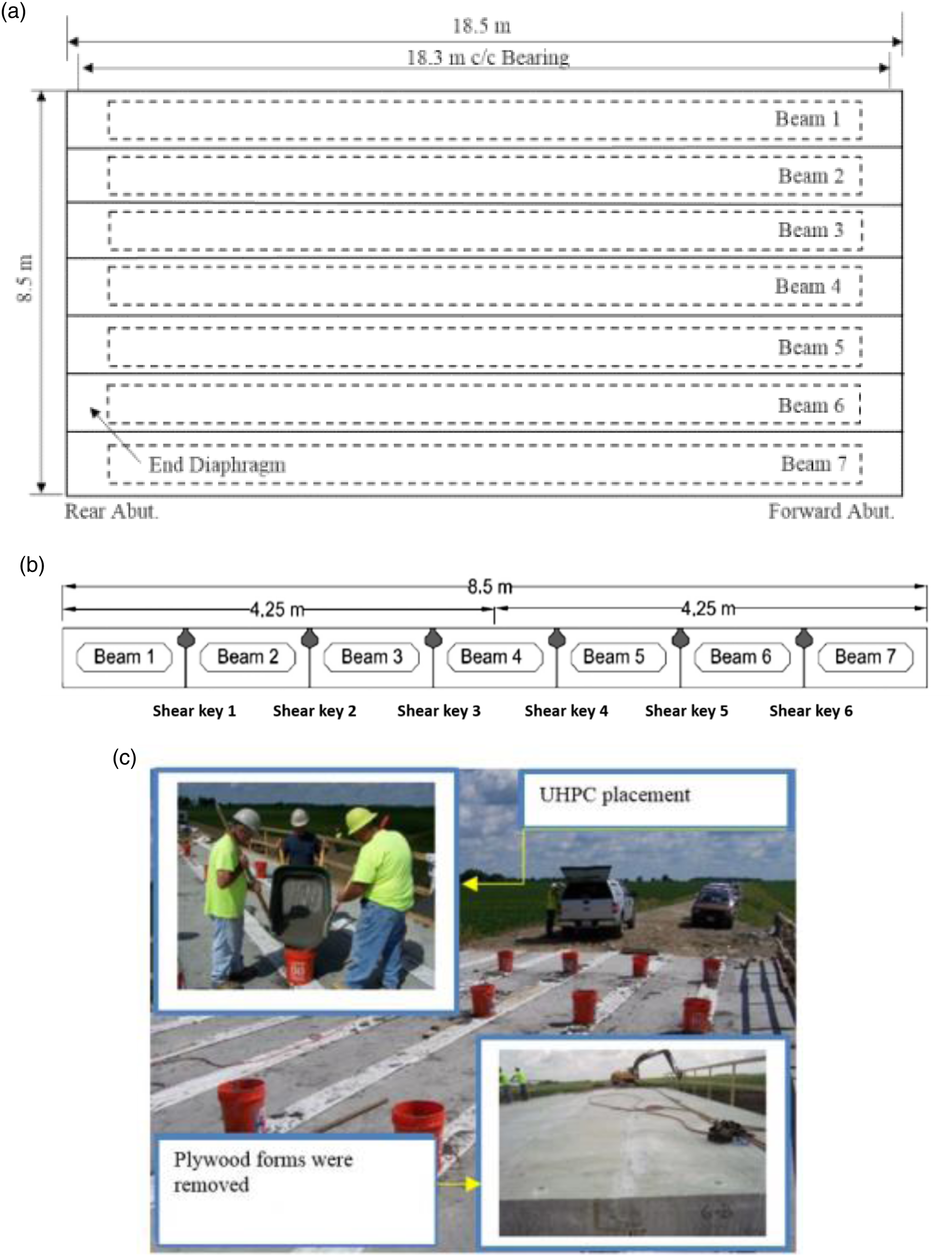
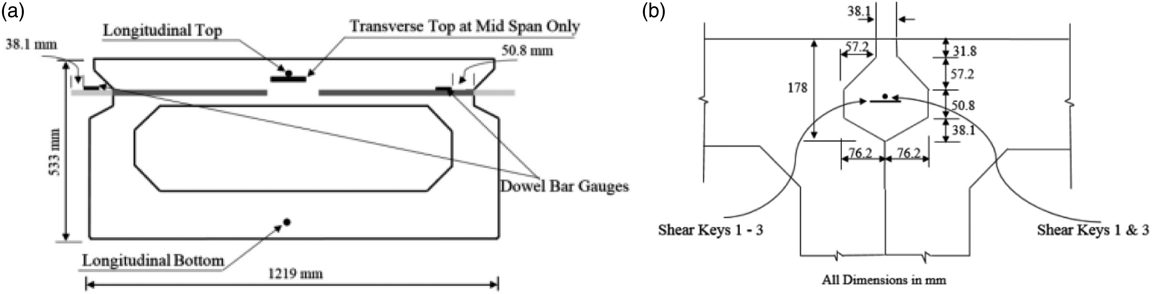
Figure 2 shows the location for the gauges at a typical instrumented section used for the model calibration. The gauges included vibrating wire strain gauges (VWSGs) embedded in the beam and shear key material to measure the transverse strain, and strain gauges attached to the reinforcement embedded in the beam as well as the shear ley. More detailed instrumentation information can be found in Semendary et al. (2017).
The data indicated that the temperature at same depth tended to be uniform throughout the bridge, although a temperature gradient with depth did existed. Figure 3 shows the average temperature change in the box beam’s top and bottom flanges and in the shear key. In the first 1.5 days after UHPC placement, the shear key temperature was generally higher than the ambient box beam temperature because of the heat of hydration. Afterward, the shear key temperature generally followed the daily temperature change. Temperature data in beam 3 and joint 3 at mid-span.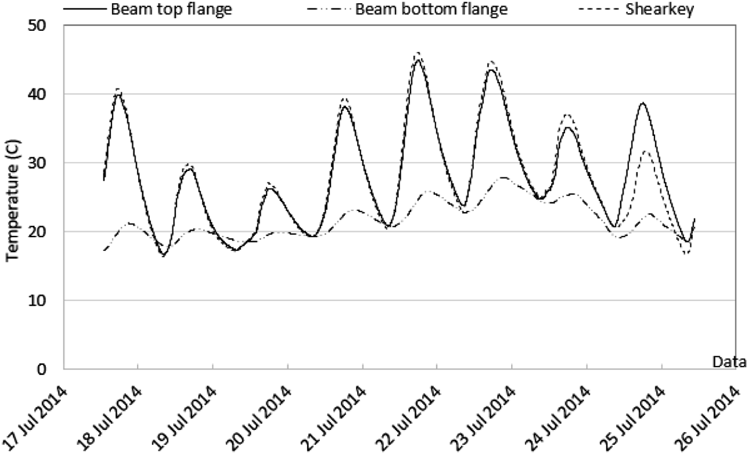
FE model development and material properties
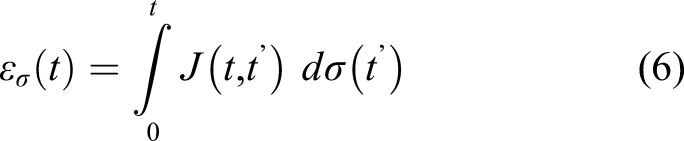
Since literature review results indicated that shrinkage and/or temperature changes were the main reasons for early age shear key cracking, a FE model was established to give insight on the performance of UHPC shear key at locations which were not instrumented during the field test. The model was established utilizing the same approach in Liu and Phares (2020b). The total strain (


The FE structural analysis was performed using ANSYS and MATLAB. The linear elastic FE Model was developed for the whole bridge superstructure including the seven beams and six shear keys and transverse dowels. The support condition under the superstructure was simplified as the vertical supports only. Additional restraints were added to prevent rigid motion. 3D solid elements were used to model the box beams and the shear keys (Figure 4) and beam elements for the transverse dowel bars that cross the box beam—shear key interfaces. The longitudinal steel and stirrups in the precast beams were ignored in the model since they have insignificant effects on the transverse stress development in the shear keys and at the interface. The pre-stressing force was also ignored as the shear keys were placed after the beams were transported to the site. The bridge did not utilize a transverse tie rods/post-tensioning strand. The concrete compressive strength used in the beams was 75.84 MPa (11 ksi). The calculated modulus of elasticity was found to be 41,286 MPa (5985 ksi). The modulus of elasticity of the dowel bars was taken to be 200,000 MPa (29,000 ksi). Since the field test did not indicate sliding/debonding at the interface between the UHPC material and box beam, perfect bond was assumed at the beam-shear key interface. The 28-days compressive strength of UHPC was 152 MPa (22 ksi). The time-dependent Young’s modulus was determined utilizing equation (2) and (4). The effect applied on the FE model for the newly jointed bridge included the shrinkage and temperature change. Due to a lack of the shrinkage data for the field UHPC material, a −170 µε shrinkage rate from Day 1 to Day 2 measured by Haber et al. (2018) on the similar type of UHPC and the proposed early age shrinkage rate curve from Yoo et al. (2014) was used. The commercially UHPC mix used in the study by Haber et al. (2018) was similar to the mix used in the bridge. Therefore, the strength gain, modulus of elasticity and shrinkage was assumed to be comparable. Furthermore, the UHPC shear key was covered immediately after casting with plywood sheets which made the curing conditions comparable to laboratory. The temperature data measured during the field test was utilized to create a thermal field on the model with an assumption of linear interpolation in the vertical direction between the temperature measurement points. The temperature data resulted in a thermal gradient through the depth of the superstructure caused by the temperature functions during the day and a temperature difference between the beam and shear key induced by the UHPC’s heat of hydration. FE Model development. Note: FE: finite element.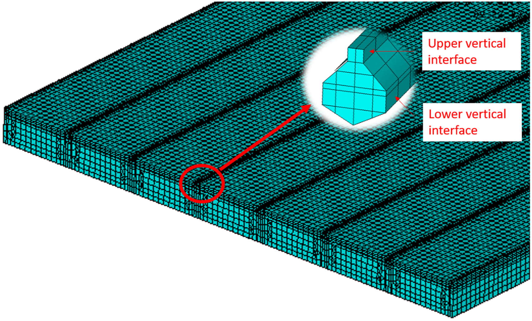
Stiffness of the shear key was not assumed to begin until 6 h after joint material placement in the FE model. The shrinkage and the temperature change were applied using a load step
Results and discussion
Model validation
The FE model was validated against the field test data collected at a frequency of 5 min from the instrumented beams, shear keys, and transverse dowel bars. Figure 5(a) and (b) compare the numerical and experimental results for the transverse strain in the top flange and longitudinal bottom strain in the bottom flange in Beam 3 at mid-span. The results from the FE model for the top and bottom flanges of the beam indicated a similar trend of the strain-temperature relation to results collected in the field. Figure 5(c) compares the strain on the dowel bar and in the joint materials. The results show that a negative strain exists from 6 h (0.25 days) to 1 day after UHPC placement because of the early age high shrinkage rate of the UHPC material. The shear key strain in the transverse direction was similar from both experimental and numerical studies. It should be noted that the strains in shear key are the total strains including the temperature and/or shrinkage strain. The dowel bar strain from the FE model was larger than the experimental results due to the assumption of perfect bond between the dowel bar and the UHPC. Figure 5(d) shows the results on the dowel bar in Beam 3. However, an agreement existed between the numerical and experimental results. This implies the FE model was able to predict the early age performance of the UHPC filled longitudinal shear key on the adjacent box beam bridge. FE Model validation: (a) and (b) beam 3 transverse and longitudinal strains in the top and bottom flanges; (c) Transverse strain in shear key 3 and dowel embedded in shear key 3 at the mid-span; and (d) Strain is dowel embedded in beam 3 at quarter span.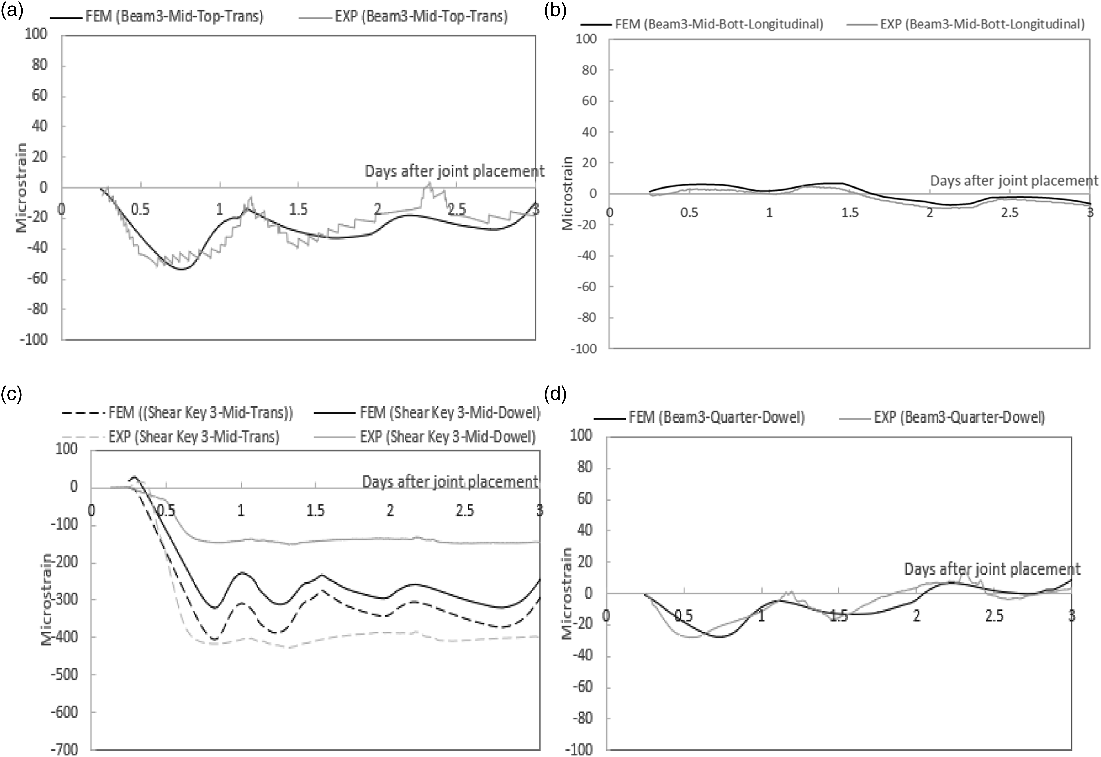
Shear key stress distribution
The maximum tensile stress of the shear key occurred inside of the joint (red area) near the end of the superstructure as illustrated in Figure 6(a). This maximum tensile stress was primarily in the transverse direction and mainly induced by UHPC shrinkage. The time-dependent stress development at the maximum location was plotted and compared with the tensile strength (see Figure 6(b). The time-dependent tensile strength curve was established utilizing Equation (1) and Equation (3). Six hours after the joint material placement, the stress in the joint continued to increase until about 24 h Due to material shrinkage. Afterward, the stress level tends to be stable with minimal changes occurring with daily temperature change. Although tensile stress continues to exist in the joint after 24 h, it was low when compared to the UHPC tensile strength. It should be noted the stress measured on the bridge should be smaller than the stress output from the FE model since concrete creep (relaxation) reduced stress. Stress development shear key: (a) Maximum tensile stress contour plot in the joint; and (b) Time-dependent stress development in the joint.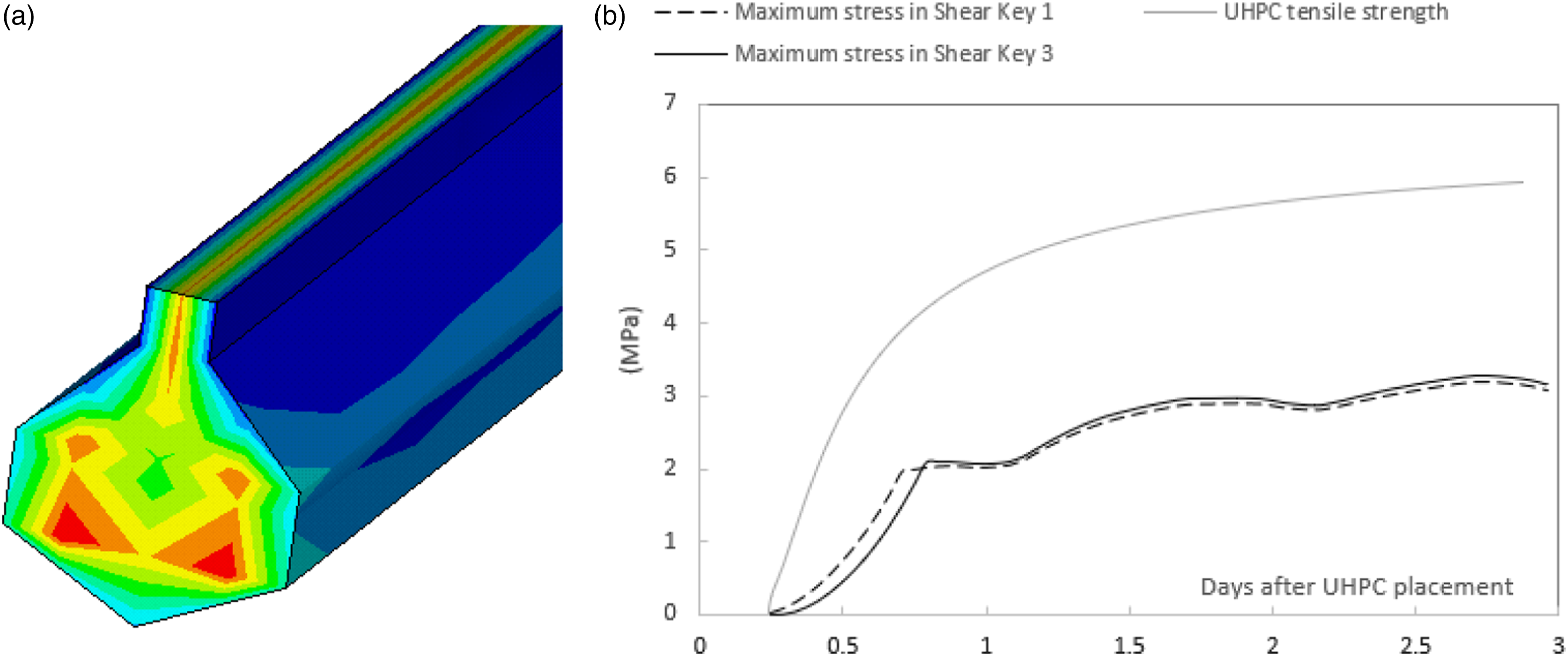
Beam-shear key stress distribution
The load at the beam-shear key interface transfers through three components: adhesion/cohesion, mechanical interlocking through shear friction, and/or dowel action of the shear reinforcement crossing the interface. The compression at the interface enhances the shear bond strength by enhancing friction while tension reduces it. Zhang et al. (2020) found a 38.5% and 50.7% decreased shear bond strength when the interface was subjected to 0.5 MPa and 1.0 MPa tensile stresses, respectively. However, the bond strength was enhanced by 27.7–79.5% when 0.5–2 MPa compressive stress was applied at the interface. The high early age shrinkage of UHPC may cause high tensile stress at the interface leading to bond failure or reducing the interfacial shear capacity. In order to investigate the early age bond at the beam-shear key interface, the shear and normal stresses from each node at the upper level vertical interface and the lower level vertical interface (Figure 7) was output. These locations experienced direct shear only as the compressive stresses from shear key geometry are not existed. So, sliding is more likely to occur. The Coulomb failure criterion was used to determine the shear bond strength, Interface compatibility (1 ksi = 6.89 MPa, 1 in. = 25.4 mm)

Figure 7 shows the analytical results on the upper and lower vertical interfaces for half of the span. The highest ratio of 0.75 occurs near the end of the span at the lower level vertical interface when joint material was 24 h old as shown in Figure 7(c) and (f). The value was less than one, which confirmed the field observation result that debonding failure did not occur during the field monitoring. The normal and shear stresses used to calculate the shear stress versus strength ratio were plotted in Figure 7(a) and (b), (d) and (e). The results indicated high shear stresses exist at the interfaces when the joint material experiences high material shrinkage. This shows similar, but opposite phenomena as the work in Liu and Phares in which expansive material was used for the joint (Liu and Phares, 2019a, 2019b). Comparison of Figure 7(b) and (e) show the upper vertical interface was generally subjected to compression when the lower vertical interface was in tension. This result is due to the lower part of the joint being wider than the upper part and generating more shrinking to pull the box beams together. The box beam resisted the shrinkage and created tension at the lower part due to restraint effects. The box beam may rotate apart from each other around the shear key which created compression at upper part because the shear key was located at the upper height between the beams. This additional compression enhances the shear capacity at the upper level vertical interface by creating a “self-lock” phenomena within the shear stress versus strength ratio. The maximum normal stress in lower vertical interface was 0.35 MPa which was much lower than the tensile bond strength of 1.90 MPa reported by Semendary and Svecova (2020) and 2.38 MPa reported by Zhang et al. (2020).
Conclusions
In this paper, a FE model was established for the superstructure of a UHPC shear key adjacent box beam bridge with a research focus on investigating the time-dependent stress distribution in the UHPC due to shrinkage and temperature. Since this bridge was previously monitored for early age joint behavior, research work in this paper focused on determining the stress distribution at non-instrumented locations. The model was developed with the ability of simulating UHPC aging and was validated against field test data. The conclusions drawn from this study are 1. The UHPC shear key stress was mainly affected by self-volume (shrinkage/expansion) change of the joint material. 2. The UHPC material in the specific shear key configuration of the study created a “self-locked” phenomenon which generated compression at the upper portion of the shear key. 3. The early age tensile stress in shear key exists due to the shrinkage effect of the UHPC and temperature. However, the magnitude of this stress was small compared to the tensile strength of UHPC. 4. The early age shrinkage of the UHPC also induced shear stress at beam-shear key interface. This confirms the findings from the literature review that the interface is a critical location and needs to be designed with sufficient capacity. The results also indicated that this shear stress is not sufficient to induce interfacial failure.
Footnotes
Author contributions
The authors confirm contribution to the paper as follows: study conception and design: A. Semendary and Z. Liu; data collection: A. Semendary; analysis and interpretation of results: Z. Liu; draft manuscript preparation: Z. Liu, A. Semendary and B. Phares. All authors reviewed the results and approved the final version of the manuscript.
Declaration of conflicting interests
The author(s) declared no potential conflicts of interest with respect to the research, authorship, and/or publication of this article.
Funding
The author(s) received no financial support for the research, authorship, and/or publication of this article.
