
Abstract
The aerodynamic characteristics of twin-separated parallel decks for long-span rail-cum-road bridges with various wind barriers clamped at railway girder are more complicated because of aerodynamic interference. Experimental investigations on aerodynamic coefficient and wind pressure coefficients of twin girders under different incoming flow directions were conducted using wind tunnel tests. Three different heights (H) varying from 2 m to 4 m and four different ventilation ratios (R) varying from 20% to 50% for wind barriers were examined. Results indicated that the aerodynamic coefficients were affected significantly by the incoming wind direction, which must be considered, and the railway wind barrier affected the aerodynamic characteristics of the railway girder when it is located both upstream and downstream, but the laws are not the same. Due to the aerodynamic interference effect of the twin parallel girders, the aerodynamic characteristics of the adjacent highway girders were also affected by the wind barrier along the railway girder, especially when the highway girders were located downstream. While, the highway girders were less affected when located upstream. The influence of wind barrier height and ventilation ratios on the adjacent highway girders was completely different. Most importantly, the parameters optimization of wind barriers clamped at railway girders should be determined after a comprehensive evaluation of the aerodynamic characteristic of both the railway and highway girders.
Keywords
Highlights
1. The effect of wind barriers installed on the railway for the aerodynamic coefficient and wind pressure coefficients of twin girders are investigated and in a wind tunnel. 2. The influence of wind barrier height and ventilation ratios on the railway girder was completely different from that of adjacent highway girder. 3. Most importantly, the parameters optimization of wind barriers clamped at railway girders should be determined after a comprehensive evaluation of the aerodynamic characteristics of both the railway and highway girders.
Introduction
Parallel configurations of long-span bridges may be in high demand to carry a growing volume of vehicle and rail traffic over vast territory as a result of modern economic expansion (He et al., 2021; Kimura et al., 2008; Stoyanoff et al., 2019). Relevant parallel bridges, the Jindo bridges in Korea, the Fred Hartman the J.P. Duarte bridges in St. Domingo, the Hongdao bridges in China, that have been built are twin parallel highway bridges. Long-span rail-cum-road bridges with twin-separated parallel decks are becoming increasingly popular bridge types in China due to their higher highway and railway traffic capacity and the economic benefits gained by avoiding the construction of two separate bridges (Liu et al., 2022). However, due to the aerodynamic interference between the railway and highway bridges, the research on wind resistance characteristics is usually more challenging (Argentini et al., 2015; Matsumoto et al., 2003). The aerodynamic interference effects of double Bridges have been widely studied (Park and Kim, 2017a; Park et al., 2017b; Seo et al., 2013; Zhou et al., 2017). It has been found aerodynamic interference effect can not be ignored for aerodynamic characteristics of parallel bridges (Chen et al., 2014; Yang et al., 2021).
On the other hand, unstable oscillations may be brought on by even a slight modification to the bridge-deck cross-section design (He et al., 2017; Li et al., 2021; Mannini et al., 2016). The appurtenances (Laima et al., 2018) such as wind fairings (Dong et al., 2021), guide vanes for maintenance traces (Hu et al., 2019), grid plates (Zhou et al., 2021), transverse inclination (Chen et al., 2023a), sealing traffic barriers at intervals (Zhang et al., 2020b), thin-walled splitter plates (Sahu et al., 2019) that have a considerable influence on the bridge. Wind barriers are a crucial piece of infrastructure for protecting passengers and employees on high-speed trains (He and Li, 2020a; Xiang et al., 2022). The wind barriers are one of the main bridge attachments. Many scholars have researched the wind protection effect and parameter optimization of wind barriers using wind tunnel tests (Chen et al., 2017, 2020; Kozmar et al., 2014), computational fluid dynamics, machine-learning prediction (Chen et al., 2023b) and theoretical analysis (Wang et al., 2022a; Xue et al., 2020). The major properties of wind barriers that determine their sheltering performance are the structure form (Gu et al., 2020), ventilation ratio and height (He et al., 2020b; Zou et al., 2022). While the protective effects of wind barriers for wind velocities, trains or vehicles are fairly known (Zhang et al., 2020a), their influence on bridges is also worth studying (Kozmar et al., 2012). Wind barriers may adversely affect the bridge’s static aerodynamic characteristics (Kozmar et al., 2014). Numerous studies related to the effect of wind barrier heights and porosity ratios have been conducted. Buljac et al. (2017, 2020) focused on effects of the wind-barrier height and ventilation ratio and various arrangements of wind barriers (windward, leeward, and both windward and leeward) on aerodynamic characteristics of three typical wide long-span cable-supported bridge decks, verified that the wind barriers strongly influence the aerodynamic force of bridge-deck sections. Guo and Tang (2018) investigated the effect of wind barrier porosity on the dynamic performance of a railway bridge and the safety of the trains using it. Ogueta-Gutiérrez et al. (2014) investigated the effects of different types of bird protection barriers on the aerodynamic and aeroelastic behavior of bridge structures by wind tunnel tests. Wind barriers affect different safety evaluation characteristics of vehicle-bridge systems. Xia et al. (2023) and Lopez-Nunez et al. (2023) conducted wind tunnel experiments to study the effect of wind barriers on the vortex-induced vibration (VIV) and aeroelastic instabilities of the deck. Li et al. (2023) clarify how the aerodynamic interference of wind barrier to the train-bridge system affects the dynamic response of the system. Cheng et al. (2023) studied the variations of the aerodynamic characteristics of the train with the length of the wind barrier for different wind barrier thicknesses using the improved delayed detached eddy simulation (IDDES) method and the shear stress transport (SST) k-ω turbulence model. Wang et al. (2022c) established the wind-train-bridge coupling system to compare the vibration responses of the train and bridge with and without a wind barrier to fully consider the wind shielding effect and train-induced wind effect on the vibration of a train-bridge system. Xiang et al. (2022) utilized a novel wind tunnel test device of a moving train model, investigated the effects of the height and porosity of the wind barriers on the protective effect for moving trains considering the aerodynamic characteristics of the moving train, and discussed the vehicle aerodynamic characteristics with and without employing the porous wind barrier.
There are also various types of geometrical structures of wind barriers. Considering the event of partial damage to the wind barriers would resulting in the deterioration of the train running safety, Han et al. (2022) aimed to assess the running safety of a CRH2 high-speed train traversing a four-tower cable-stayed bridge with damaged wind barriers. For the vertical fence-type wind barriers, Wei et al. (2022) investigated the aerodynamic characteristics of a train–bridge system of curved and vertical fence-type wind barriers, and the results show that, compared with the vertical wind barrier, the curved wind barrier can reduce the drag force and moment of a train while reducing the impact of the aerodynamic forces on a bridge. In addition, Lou et al. (2022) studied the effects of curved wind barriers with four curvatures (0, 0.2, 0.35, and 0.50) and different train-bridge combinations on the crosswind aerodynamic characteristics of a train-bridge system, and the wind barrier with a curvature of 0.35 is recommended. The wind barrier can not only be used to prevent the wind to ensure the stability of the train, but also can be combined with the sound barrier to play a variety of roles such as noise reduction and pressure relief. Jiang et al. (2022) proposed a new type of wind–noise barrier (NT-WNB) to meet the wind resistance and noise reduction requirements of the elevated lines crossing an urban area at the same time with numerical and wind tunnel tests. However, the influence of the wind barriers on the aerodynamic characteristics of large-span bridges in parallel should also be considered for the aerodynamic interference effect.
According to the aforementioned literature assessment, the existing study on the effect of wind barriers on static aerodynamic features is constrained in that it only takes into account one bridge rather than a thorough analysis of the twin girders' entire aerodynamic characteristics, which also should be considered the aerodynamic interference of wind barriers. For asymmetric twin-separated parallel decks of long-span rail-cum-road bridges, the aerodynamic characteristics are more complex after the wind barriers are added. What is the difference in the effect of installing railway wind barriers on the aerodynamic characteristics of railway bridges under the influence of adjacent highway girders? Are the aerodynamic characteristics of highway girders also affected by wind barriers at the railway girder under different directions of incoming flow? What are the differences in the influence characteristics of the wind barrier parameters (heights, ventilation ratios) when considering the aerodynamic interference effect? All these issues need to be considered in the study of the effect of wind barriers on twin girders. Thus, it is interesting to investigate the effects of the wind barriers on the aerodynamic characteristics of twin-separated parallel decks for long-span rail-cum-road bridges.
In this study, based on the subject of twin-separated parallel decks, experimental investigations on aerodynamic coefficient and wind pressure coefficients of twin girders under different incoming flow directions with various wind barriers were conducted using wind tunnel tests. Three different heights (H) varying from 2 m to 4 m and four different ventilation ratios (R) varying from 20% to 50% for wind barriers were used to investigate the effect of heights and ventilation ratios. As a result of the research, long-span rail-cum-road bridges with different wind barriers could have more accurate evaluations of the static aerodynamic characteristics of these twin-separated parallel decks.
Wind tunnel test
Engineering background
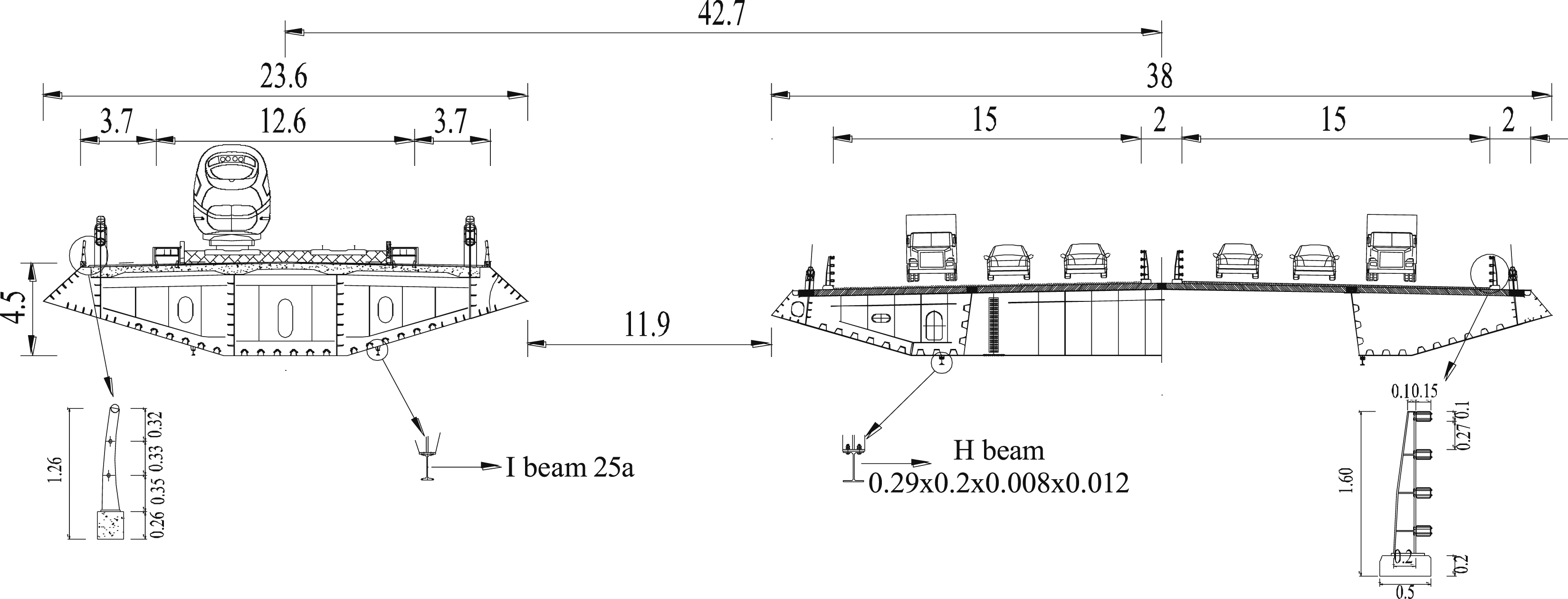
The bridge is a highway-railway leveling cable-stayed bridge, the configuration of the bridge and standard cross-section configuration is shown in Figures 1 and 2, respectively. The bottom surfaces of the two decks that make up the double-width main beam are flush with each other. More detailed description about the long-span rail-cum-road bridge with twin-separated parallel decks can be seen in related papers (Liu et al., 2022, 2023). Wind barriers will be installed on both sides of the railway girder instead of the handrail. Corrugated wind barrier with circular opening form is a typical railway wind barrier, which have been widely used in western China such as Lan-Xin Railway due to their sheltering and dustproof features, simple installation, and low cost (Gu et al., 2020). The overall configuration of twin parallel cable-stayed bridges (unit: m). Cross-sections of highway and railway girders (unit: m).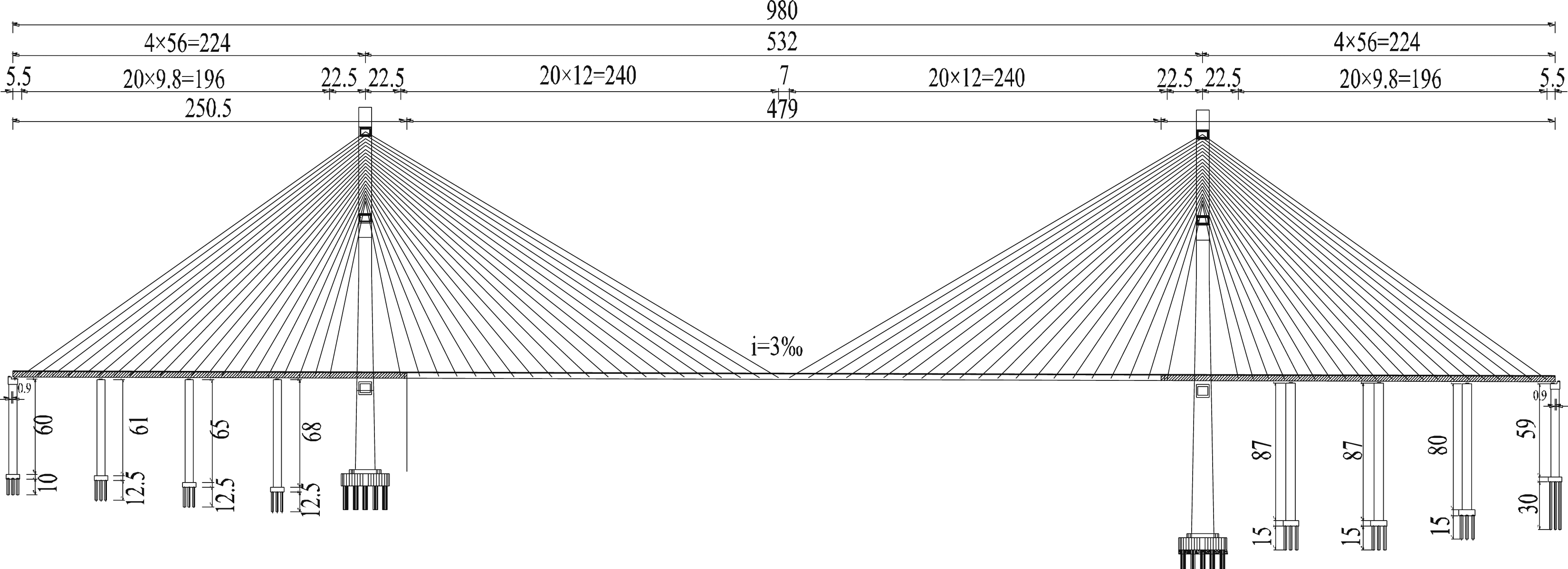
Experimental setups
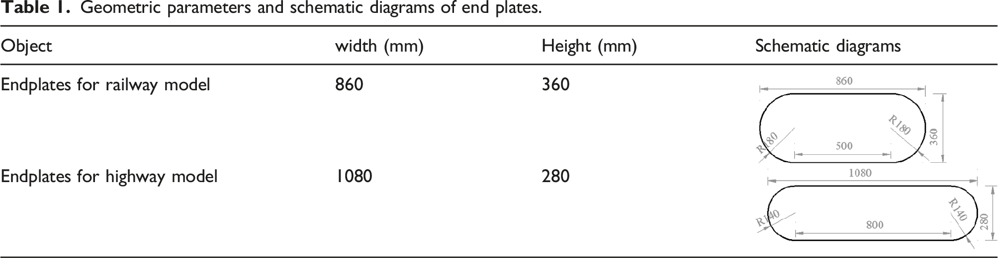
The section model wind tunnel tests were conducted in the wind tunnel laboratory of Central South University with a section size of 3.0 m (width) × 3.0 m (height) × 15.0 m (length) under smooth flow conditions. To systematically examine the impact of wind barriers on parallel twin girders with road-rail separation, experiments were done with the same geometric scale ratio of 1:50 and structural parameter. The wind tunnel test section's obstruction is approximately 3%, which meets the standards. As shown in Figure 3, the sectional model was attached to the high-frequency balances that were put on the ends of the girders. In the tests with 0° wind-attack angles, the mean wind speed is 20 m/s, and the turbulence intensity is in the range of 0.5%–1%. The Reynolds number of the highway and railway models are 8.6 × 10⁴ and 11.0 × 10⁴. Reynolds number Re of the tests model was calculated by Re = ρVD/μ, where ρ = 1.225 kg/m3 and μ = 1.79 × 10⁻⁵ N/m2·s denote the density and viscosity coefficient of the air. The drag force coefficient, the lift force coefficient, and the lifting moment coefficient were measured for highway and railroad girders with different wind barriers. To weaken the 3D end effect of the flow (Li et al., 2019), rectangular wood end plates with rounded corners (Wang et al., 2022b) were attached to both ends of the models by screws without unwanted vibration. The thickness of end plate was 5 mm, and other geometric parameters and schematic diagrams are listed in Table 1. Examples of wind tunnel tests for measuring aerodynamic coefficients. (a) Model of highway and railway girders. (b) Model of wind barriers (H3-R50%). Geometric parameters and schematic diagrams of end plates.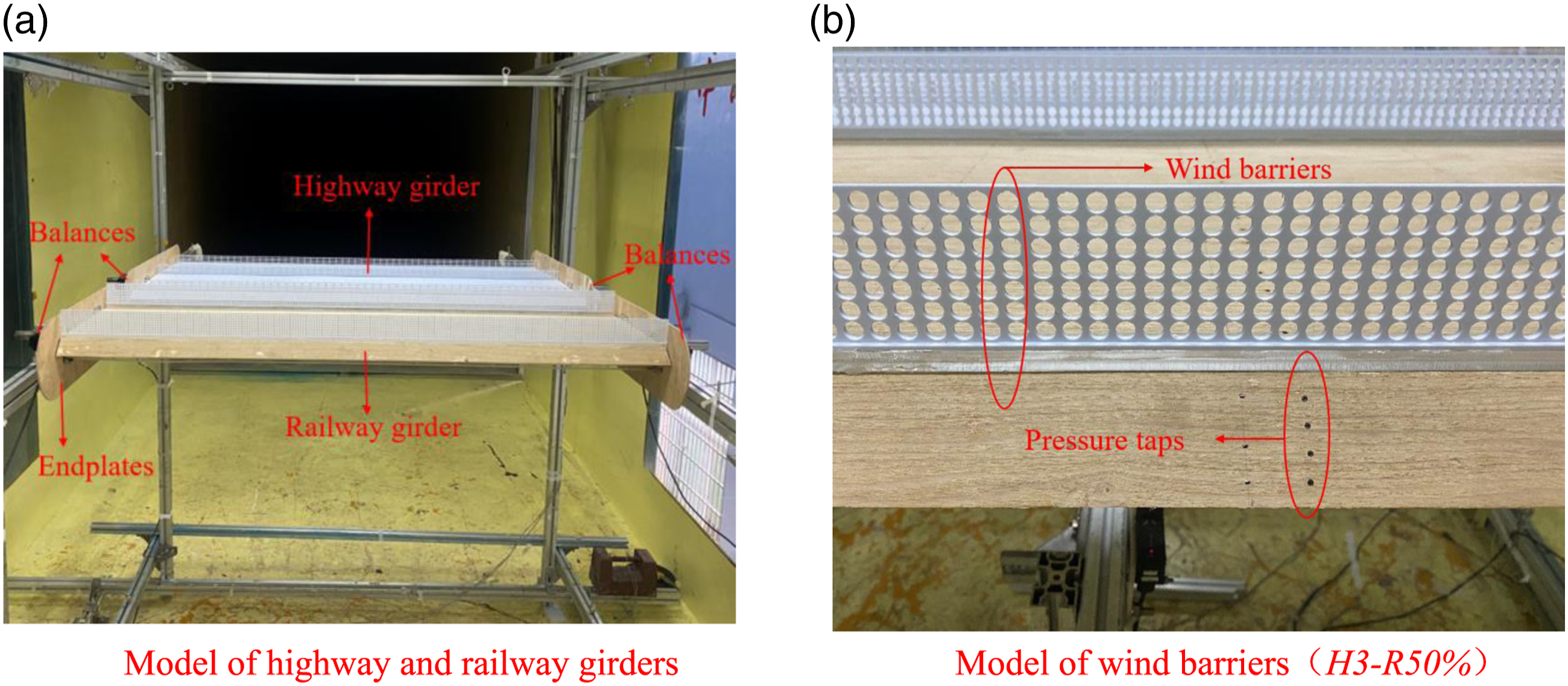
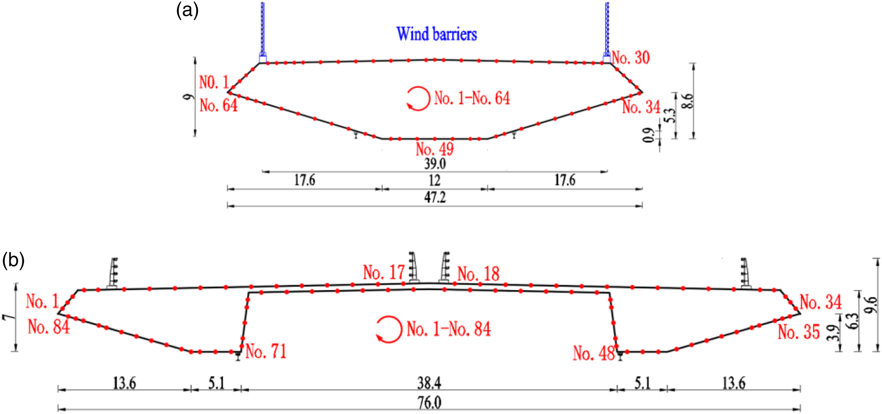
The scanning valve system is used to monitor the wind pressure coefficient with the sampling frequency of 330 Hz. Figure 4 shows the schematic diagram of different directions of the incoming flow and aerodynamic forces. Using high-quality lumber and ABS plates, we were able to successfully mimic the twin deck’s aerodynamic design while also ensuring the model was sufficiently stiff. Figure 5 displays the positioning of the pressure holes arrangement and the exact measurements of the two decks. Schematic diagram of different directions of the incoming flow and aerodynamic forces. (a) Wind flows from the railway to the highway. (b) Wind flows from the highway to the railway. Cross-section dimensions and locations of pressure taps (unit: cm): (a) railway; (b) highway.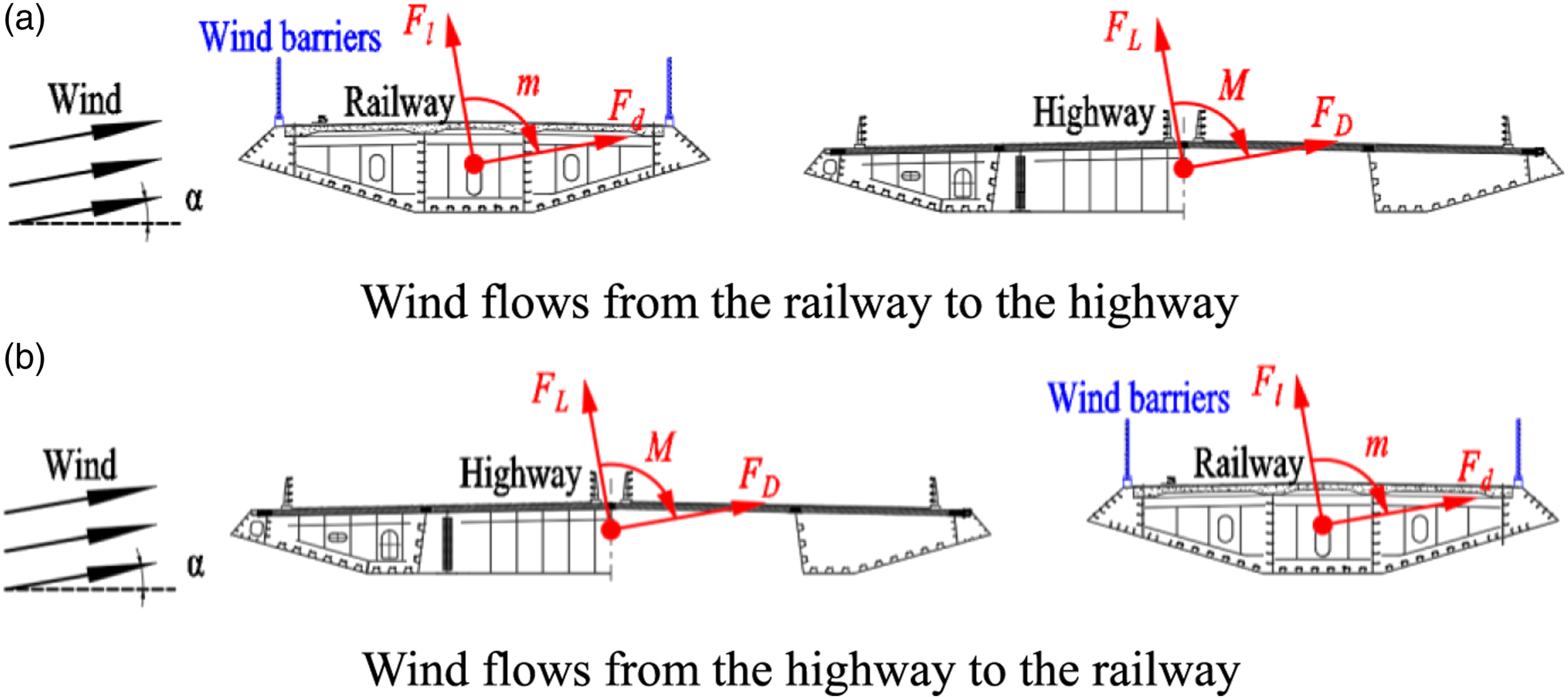
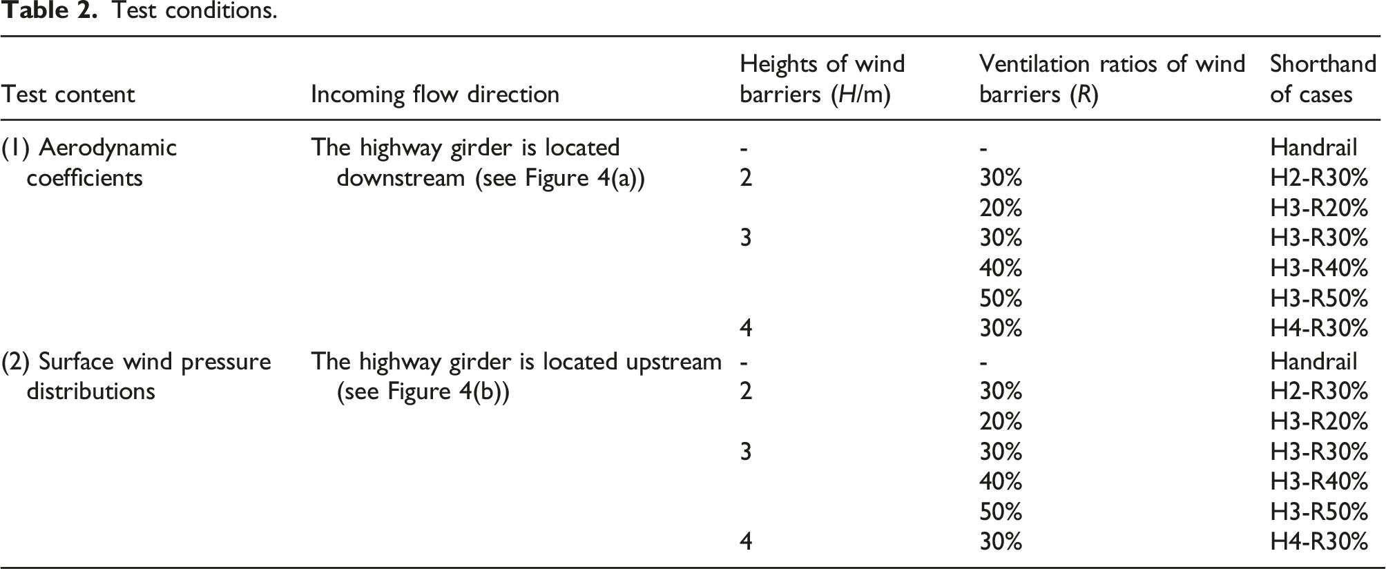
For the safety of bridges and trains, it is thought that the height and ventilation ratio of wind barriers at the railway girder are important considerations. To study comprehensively the effect of wind barriers on the aerodynamic characteristics of the twin-separated parallel girders. Wind barriers with four different ventilation ratios and three different heights were established, as shown in Figure 6. The circular holes wind barrier is a typical simplified opening form of wind barrier (Wang et al., 2022a), which was used to simplify corrugated railway wind barrier (Gu et al., 2020). Detailed conditions are shown in Table 2. Wind barriers will be installed on both sides of the railway girder instead of the handrail. Structural parameters of wind barriers. (a) Various ventilation ratios among wind barriers (H = 3 m). (b) Various heights among wind barriers (R = 30%). Test conditions.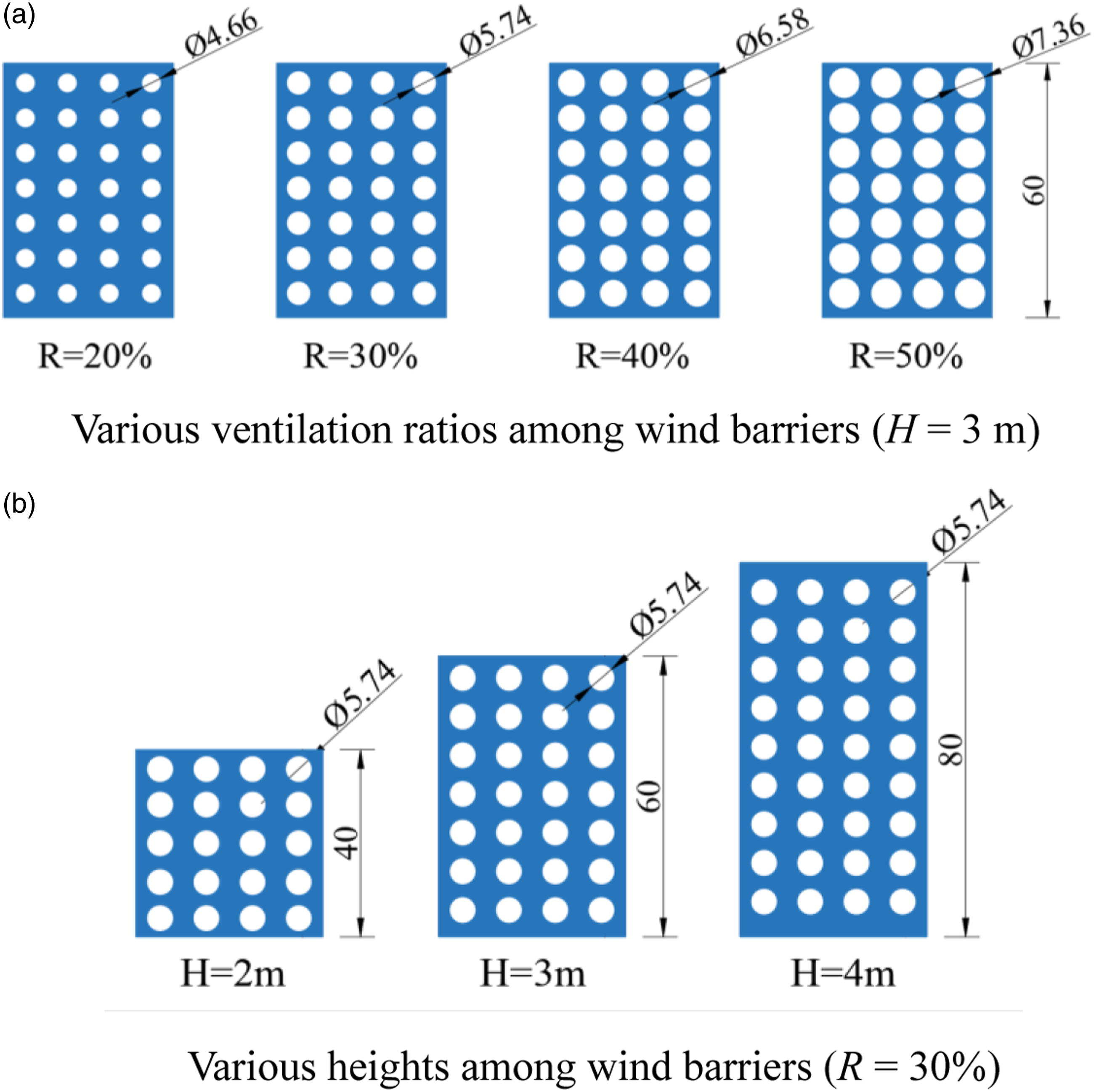
Data processing
The aerodynamic forces of the bridge are defined as (He et al., 2017):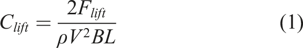
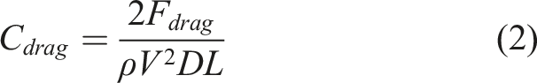
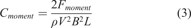
Where D is the height; B is the width; L is the length. CL, CD and CM are the lift coefficient, drag coefficient and lifting moment coefficient of the highway bridge per unit length. FL, FD and FM are the lift, drag and moment of the highway bridge. While, Cl, Cd and Cm are the lift, drag, and lifting moment coefficients of the railway bridge per unit length. Fl, Fd and Fm are the lift, drag and moment of the railway bridge, respectively; ρ is the air density, ρ = 1.225 kg/m3; and V is the mean wind speed (Liu et al., 2022).
The dimensionless wind pressure coefficient are defined as (Hu et al., 2019; Liu et al., 2021):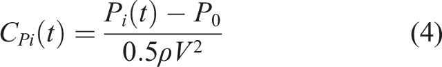


Effect of ventilation ratios of wind barriers
To compare the impacts of four different ventilation ratios (R = 20%, 30%, 40%, and 50%) on the aerodynamic characteristics of twin girders under various incoming flow directions, wind barriers of H = 3 m were used as an example in this section.
Aerodynamic coefficient of twin girders
For railway girders, the installation of railway wind barriers is detrimental to railway bridges, the girders have significantly higher drag coefficients, and the ventilation ratio of wind barriers has an impact, but the results are not the same when the railway girders are located upstream and downstream. As shown in Figure 7, the effect of different ventilation ratios (R = 20%, 30%, 40%, 50%) on the aerodynamic coefficient is compared with 3 m high wind barriers as examples. When wind flows from the railway girder to the highway girder, with the increase in ventilation ratio of the railway wind barriers, the drag coefficient of the railway decreases, the lift coefficient increases and the absolute value of the torque coefficient increases slightly. This is consistent with the results of the single girder. However, when wind flows from the highway girder to the railway girder, the drag coefficient of the downstream railway becomes obviously smaller due to the shading of upstream girder. With the increase in the ventilation ratio of the railway wind barrier, the drag coefficient of the railway also decreases, but the absolute value of the lift coefficients tends to decrease. The absolute values of the lifting moment coefficients are almost unchanged. Aerodynamic coefficients of the railway girder.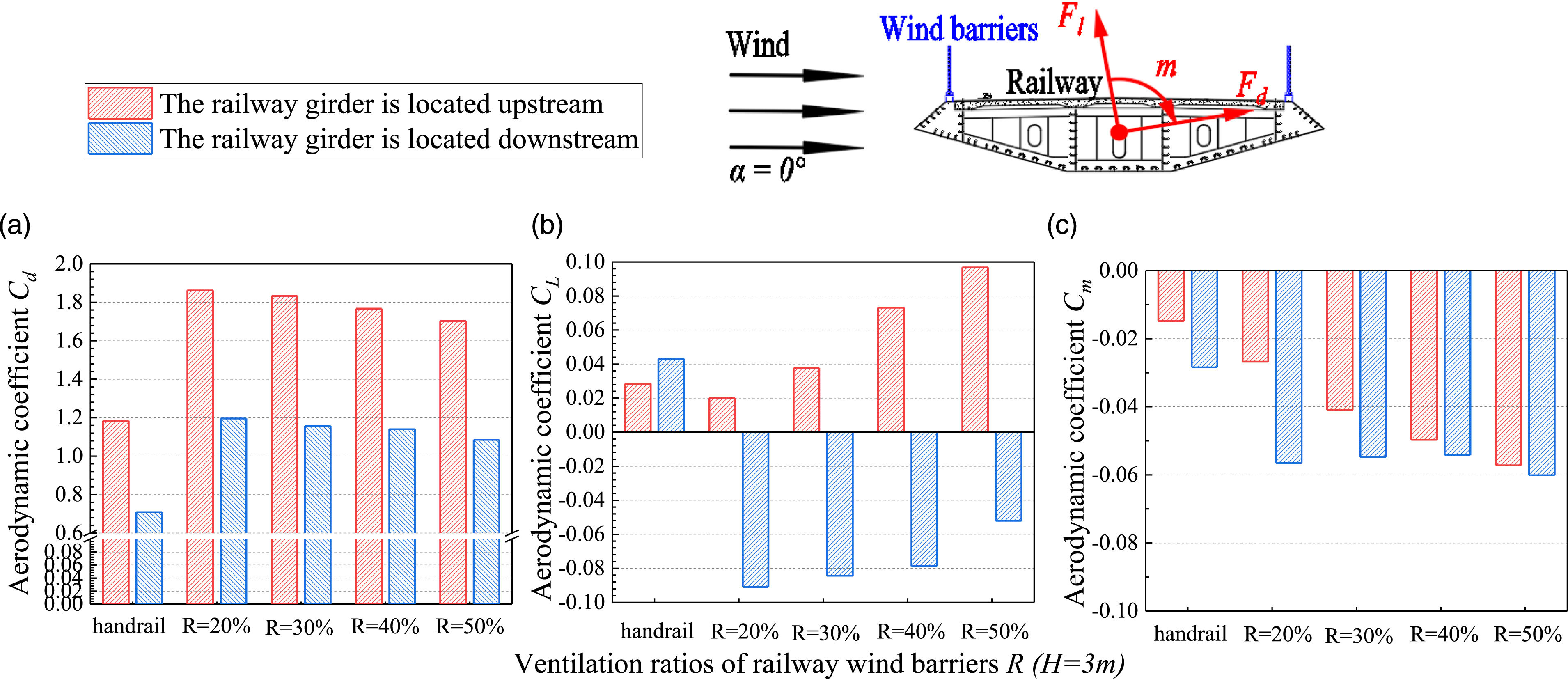
Due to the tight spacing between the railway and the highway girders and the presence of aerodynamic interference effects, even though the aerodynamic shape of the highway girder has not changed, the installation of the wind barrier at the railway girder will also affect the highway girder. As shown in Figure 8, when wind flows from the highway girder to the railway girder, the airflow acts on the highway girder first. Under different railway wind barrier ventilation ratios, the drag coefficient, lift coefficient and lifting moment coefficient of the highway girder are almost the same, and the influence of railway wind barrier is smaller. When wind flows from the railway girder to the highway girder, the airflow acts on the railway girder first. The upstream railway has a shading effect on the highway girder, which has a small drag coefficient of about 0.2. As the ventilation ratio increases, the drag coefficient of the downstream highway girder remains basically unchanged, while the absolute value of the lift coefficient becomes larger and the absolute value of the torque coefficient gradually decreases. The influence of the railway wind barrier ventilation ratio cannot be ignored. Aerodynamic coefficients of the highway girder.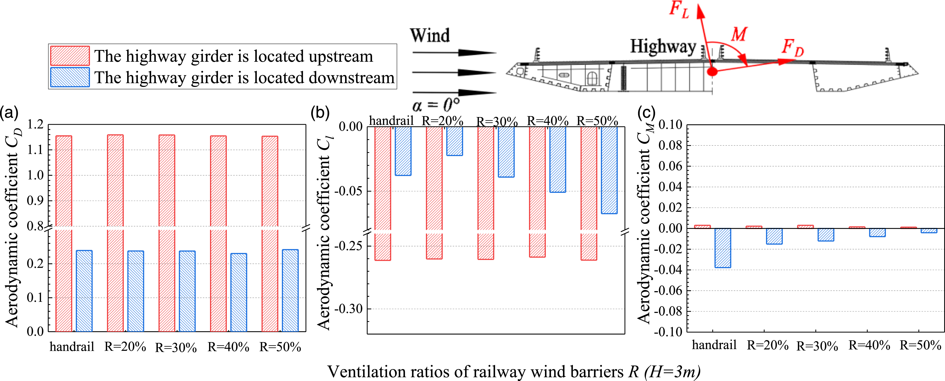
Mean wind pressure coefficients of twin girders
The detailed effects of the influence of wind barriers on all surfaces of the highway and railway girder may be seen in the surface pressure distributions of the twin girders. The mean wind pressure coefficients are chosen for examination in this section to help understand how the airflow on the train surface separates and reattaches under various wind barrier designs. As shown in Figures 9 and 10, the effect of different ventilation ratios (R = 20%, 30%, 40%, 50%) on the mean wind pressure coefficient is compared with wind barriers of H = 3 m as an example when the railway girder is displaced upstream and downstream. CP, mean of twin girders (The highway is located downstream). (a) Upper surface (Pressure taps, No.1-33 of railway, No.1-34 of highway). (b) Lower surface (Pressure taps, No.34-64 of railway, No.35-84 of highway). CP, mean of twin girders (The highway is located upstream). (a) Upper surface (Pressure tap, No.1-34 of highway, No.1-33 of railway). (b) Lower surface (Pressure tap, No.35-84 of highway, No.34-64 of railway).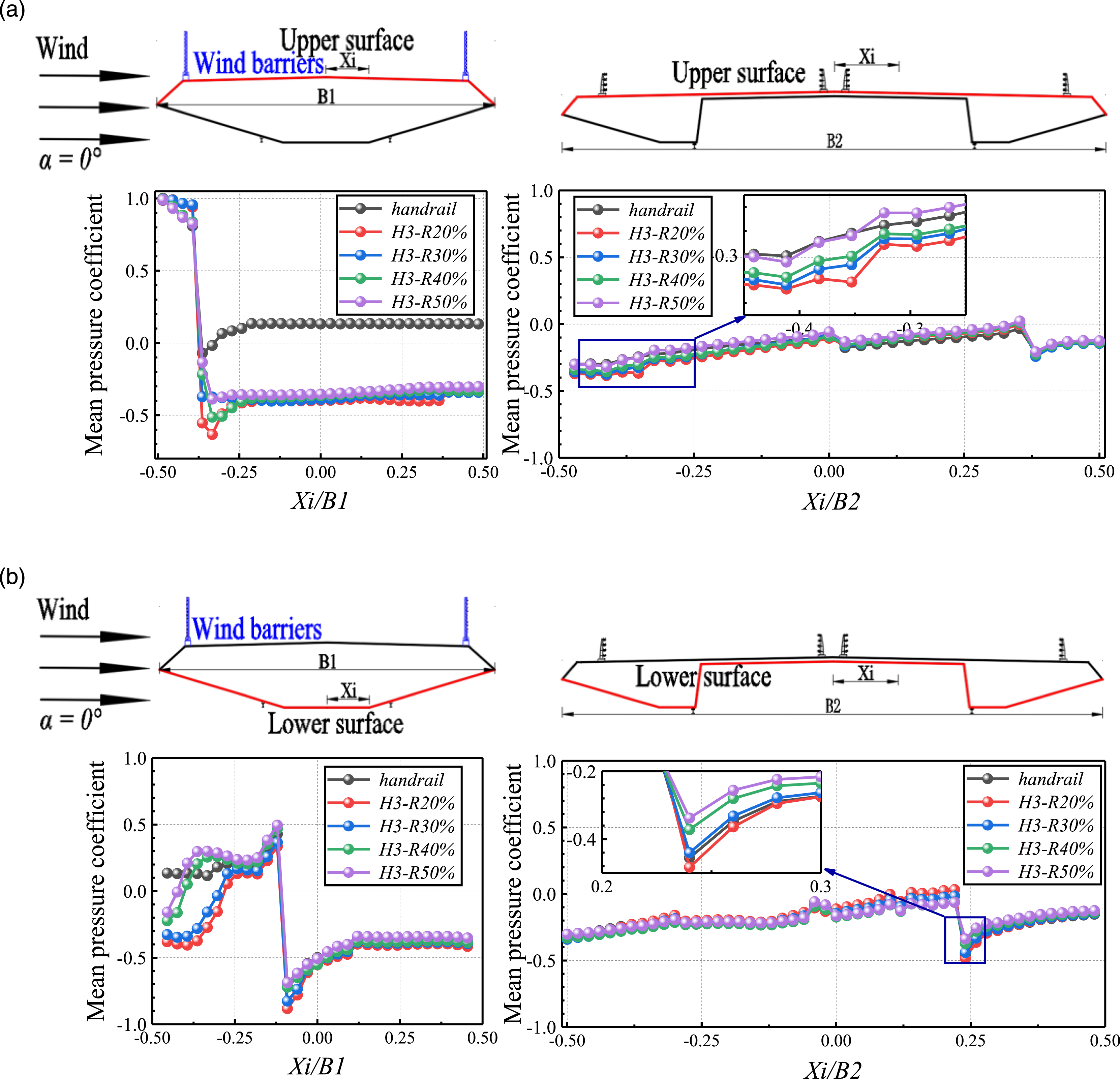
As shown in Figure 9, the ventilation ratio of the railway wind barrier not only affects the upstream railway girder, but also affects the mean wind pressure coefficient of the downstream highway girder. However, the magnitude of the effect is quite different. For the upstream railway, the installation of railway wind barriers makes the mean wind pressure coefficient on the upper surface of the railway become negative, and the mean wind pressure coefficient on the lower surface is also affected, especially on the windward side of the railway (Xi/B1 = −0.5 ∼ −0.25). When R = 20%, the ventilation ratio is small, on the one hand, the airflow cannot pass the wind barrier smoothly, but more separation occurs at the wind nozzle, forming a large negative pressure area on the lower surface of the railway girder (see Figure 9(b).). On the other hand, the airflow separates at the top of the wind barrier, creating a negative pressure zone on the surface of the upstream railway girder behind the wind barrier (see Figure 9(a)). And when the ventilation ratio of the wind barrier is increased to R = 50%, the airflow can pass smoothly. The maximum negative pressure on the upper surface of the railway girder becomes smaller in absolute value, and the negative pressure range on the lower surface also becomes significantly smaller. Therefore, with the increase in ventilation ratio, the maximum negative pressure behind the windward wind barrier of the upper surface of the railway girder gradually decreases in absolute value, and the mean wind pressure coefficient in the negative pressure zone gradually becomes smaller. The separation of airflow on the lower surface also changes, and the windward side (Xi/B1 = −0.5 ∼ -0.25) on the lower surface of the railway girder is more affected by the wind barrier ventilation ratio, and the wind pressure on the leeward side (Xi/B1 = 0.25 ∼ 0.5) on the lower surface of the railway girder is less affected.
For the downstream highway girder, it is under negative pressure and essentially entirely in the shelter of the upstream railway girder, regardless of the ventilation ratios of the wind barrier. When R = 20%, the ventilation ratio is small and the airflow cannot pass the upper surface of the railway girder smoothly, but more passes through the lower surface of the railway and then acts on the highway girder. The windward side of the upper surface (see Figure 9(a)) and the windward side of the upper surface (see Figure 9(b)) of the downstream highway girder are less affected or almost not affected. With the increase in ventilation ratio of the railway wind barrier, the trend of the mean wind pressure coefficient curve on the upper surface of the downstream highway girder does not change, but the absolute value of the mean wind pressure coefficient gradually decreases, especially on the windward side of the upper surface of the downstream highway main girder, and the leeward side of the upper surface is affected less or almost not. The leeward side of the lower surface of the highway girder is affected to a greater extent than the windward side of the lower surface.
When wind flows from the highway girder to the railway girder, the mean wind pressure coefficients on the surfaces of the twin girders are shown in Figure 10. For the downstream railway girder, which is shaded by the upstream highway girder, the positive pressure becomes smaller, and it shows a negative pressure area on the upper surface. After installing the wind barrier, the absolute value of wind pressure coefficient in the negative pressure area on the upper surface becomes larger, and the mean wind pressure coefficient on the lower surface is also affected, especially on the windward side of the railway girder (Xi/B1 = −0.5 ∼ −0.25). When R = 20%, the ventilation ratio is small and the airflow cannot pass through the wind barrier smoothly, and separation occurs at the top of the wind barrier, forming a negative pressure area on the surface of the railway upstream behind the wind barrier (see Figure 10(a)), which was same as when the railway girder is located upstream. When the ventilation ratio of the wind barrier increases to 50%, the airflow can pass smoothly and the maximum negative pressure on the upper surface becomes smaller in absolute value. The downstream railway girder is mainly affected by the tail flow of the highway girder, and the tail flow acts directly on the upper and lower surfaces of the wind nozzle of the railway (Xi/B1 = −0.5∼−0.25), and the mean wind pressure coefficients on the upper and lower surfaces of the wind nozzle are positive. This is different from when the railway girder is located upstream where it is directly affected by airflow, that the air flow did not separate on the lower surface of the railway girder to form a negative pressure zone. However, the ventilation ratio still has an effect on the mean wind pressure coefficient on the upper and lower surfaces. With the increase in ventilation ratio, the absolute value of maximum negative pressure behind the windward wind barrier of the upper surface gradually decreases, and the mean wind pressure coefficient in the negative pressure area gradually becomes smaller. The windward side (Xi/B1 = −0.5 ∼ −0.25) on the lower surface of the railway girder is more influenced by the ventilation ratio of the wind barrier, and the positive pressure value gradually becomes larger with the increase of the ventilation ratio. The wind pressure on the leeward side of the lower surface of the railway girder is less affected (Xi/B1 = 0.25∼0.5), and the mean wind pressure coefficients are almost the same. For the upstream highway girder, the airflow acts on the upstream highway girder first and is less influenced by the downstream railway wind barrier. Under different ventilation ratios, only the mean wind pressure coefficient curves on the upper and lower surfaces of the leeward side area (Xi/B2 = 0.25∼0.5) do not completely overlap and are weakly affected, but the effect is much smaller when the highway girder is located upstream than when the highway girder is located downstream.
Therefore, the mean wind pressure coefficient of the upstream highway girder is not affected by the ventilation ratios of the wind barrier along railway girder; the downstream highway girder is almost completely blocked by the upstream railway girder, and the surface of the highway girder shows negative pressure, which is also less affected by the ventilation ratios. The mean wind pressure coefficient of the upstream railway girder is affected by the ventilation ratios of the wind barrier; the downstream railway girder is shielded by the upstream highway girder, but the shielding is incomplete, and a positive pressure area appears at the windward side of the downstream railway girder at the wind spout, and the windward side of the downstream railway girder is more affected by the wind barrier ventilation ratios.
Fluctuating wind pressure coefficients of twin girders
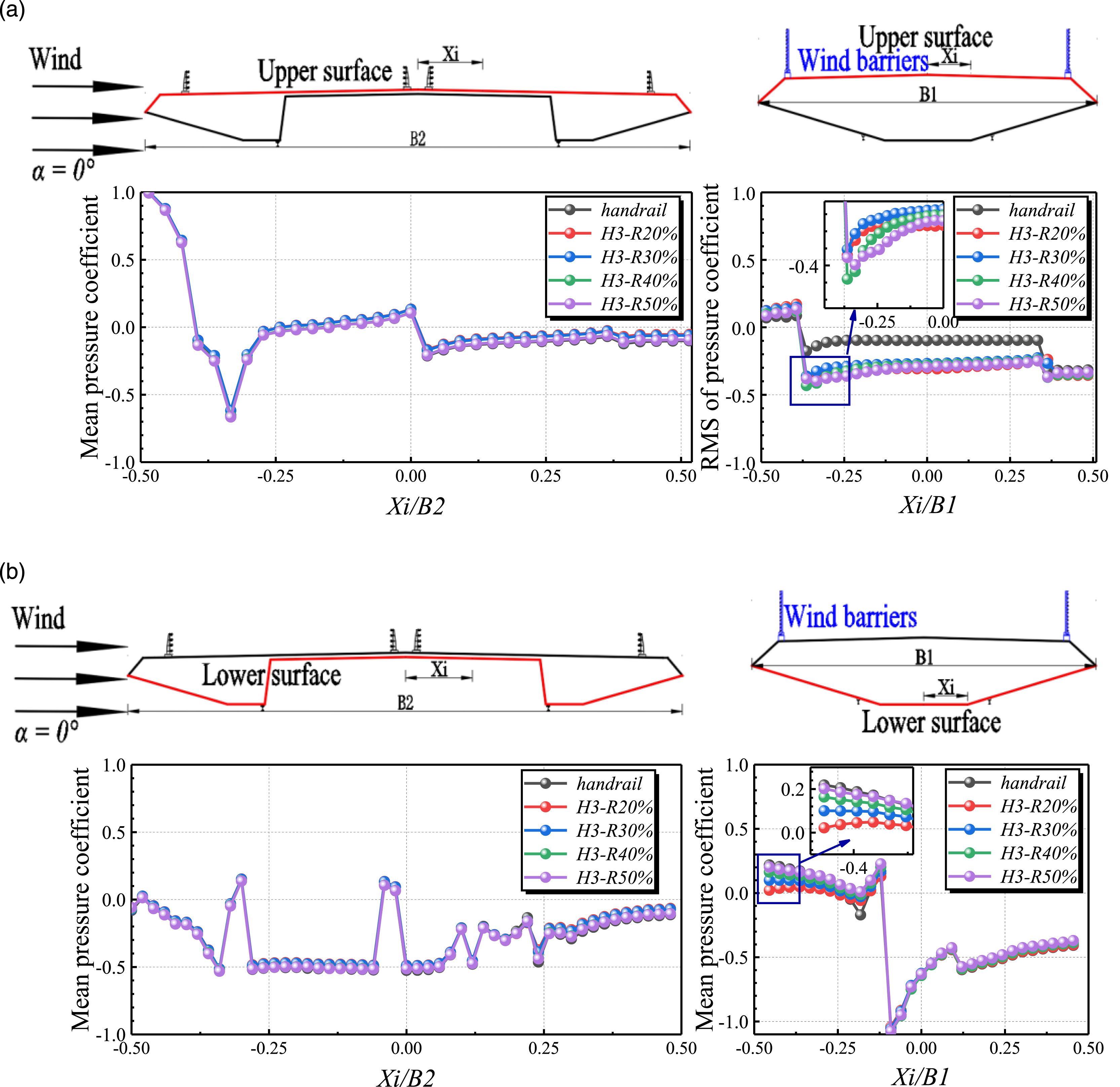
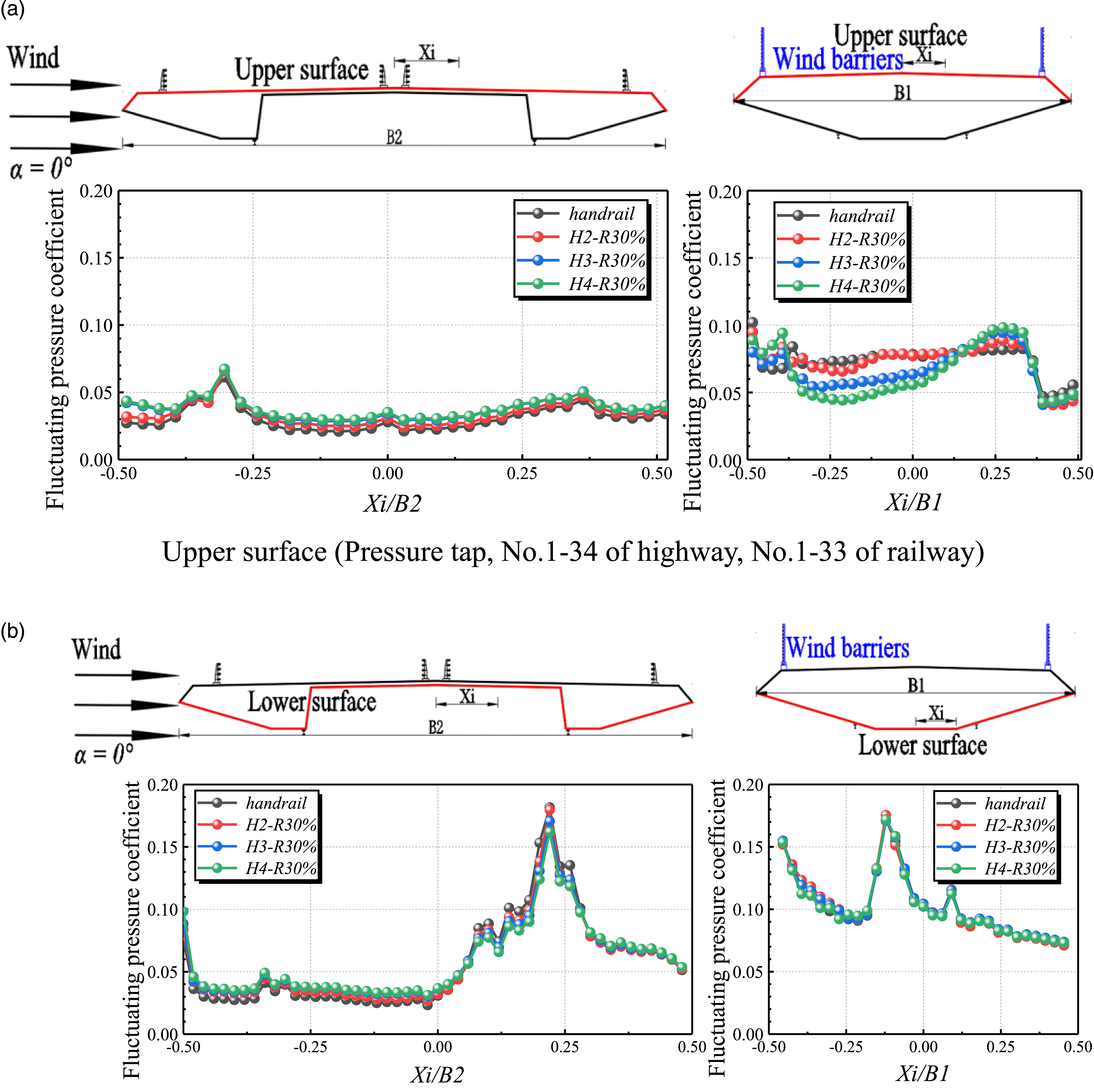
The fluctuating wind pressure coefficients on the surface of the upstream railway and the downstream highway girder are shown in Figure 11. The ventilation ratio of the railway wind barrier also has a large influence on them. For the upper surface of the upstream railway girder (see Figure 11(a)), there is an area of airflow separation behind the windward wind barrier where the airflow pulsation is strong (Xi/B1 = -0.33) because of a portion of the airflow separates at the top of the wind barrier. As the ventilation ratio of the wind barrier increases, the peak fluctuating wind pressure coefficient gradually decreases and the pulsation becomes weaker. The fluctuating wind pressure coefficients at the remaining positions are basically the same and are not affected by the wind barrier ventilation ratio. For the lower surface of the upstream railway girder (see Figure 11(b)), as part of the airflow separated at the wind nozzle, a large negative pressure area was formed on the lower surface of the railway girder (Xi/B1 = −0.5 ∼ −0.25), where the airflow pulsation was strong and the peak fluctuating wind pressure appeared, while with the increase of ventilation ratio, the peak size of the pulsating wind pressure coefficient almost remained the same, but the position gradually moved to the wind nozzle, which was also related to the gradual reduction of the negative pressure area. The other positions are basically the same and are not affected by the wind barrier ventilation ratio. For the downstream highway girder (Figure 11(a)), the wind pressure pulsatility of both the upper and lower surfaces of the highway girder is affected by the railway wind barrier due to receiving the tail flow of the upstream railway girder. As the wind barrier ventilation ratio increases, the fluctuating wind pressure coefficient on the upper and lower surfaces of the highway girder gradually decreases, but the trend does not change, and when the wind barrier permeability increases to R = 40%, the variation degree of the fluctuating wind pressure coefficient gradually becomes weaker. CP, rms of twin girders (The highway is located downstream). (a) Upper surface (Pressure tap, No.1-33 of railway, No.1-34 of highway). (b) Lower surface (Pressure tap, No.34-64 of railway, No.35-84 of highway).
When wind flows from the highway girder to the railway girder, the fluctuating wind pressure coefficients are shown in Figure 12. For the upper surface of the downstream railway girder (see Figure 12(a)), the peak of the fluctuating wind pressure coefficient on the upper surface appears at Xi/B1 = 0.25 on the leeward side of the railway and the pulsation on the upper surface is all stronger. As the ventilation ratio of the railway wind barrier increases, the peak fluctuating wind pressure coefficient gradually decreases and the pulsatility becomes weaker. The fluctuating wind pressure coefficient on the lower surface is basically the same and is not affected by the ventilation ratio of the wind barrier. For the upstream highway girder, when the ventilation ratio of the railway wind barrier is changed, the wind pressure coefficients on the upper and lower surfaces don't change much and don't depend on the ventilation ratio. CP, rms of twin girders (The highway is located upstream). (a) Upper surface (Pressure tap, No.1-34 of highway, No.1-33 of railway). (b) Lower surface (Pressure tap, No.35-84 of highway, No.34-64 of railway).
Therefore, the fluctuating wind pressure coefficients of the upstream highway girder are not affected by the ventilation ratios of wind barriers along railway girder; the downstream highway girder is almost completely blocked by the upstream railway girder, as the ventilation ratios of the upstream railroad wind barrier increases, the fluctuating wind pressure coefficient of the downstream highway girder gradually becomes smaller. The fluctuating wind pressure coefficients of the upstream railway girder on the upper and lower surfaces are affected by the ventilation ratios of the wind barrier; the downstream railway girder is shielded by the upstream highway girder, but the shielding is incomplete, and fluctuating wind pressure on the lower surface is not affected by the ventilation ratios of the wind barrier, but as ventilation ratios go up, the fluctuating wind pressure coefficient on the upper surface goes down.
Effect of heights of wind barriers
The height and ventilation ratio are the two main parameters of wind barriers. In this section, wind barriers of R = 30% were taken as an example to compare the effects of different heights (H = 2 m, 3 m, 4 m) of wind barriers on the aerodynamic characteristics.
Aerodynamic coefficient of twin girders
For railway girders, the installation of railway wind barriers is detrimental to railway bridges, the girders have significantly higher drag coefficients, and the height of wind barriers also has an impact, but the results are not exactly the same when the railway girders are located upstream and downstream. As shown in Figure 13, the effect of different heights (H = 2 m, 3 m, 4 m) on the aerodynamic coefficient is compared with the wind barrier of R = 30% as an example when the railway girder is displaced upstream and downstream. When wind flows from the railway girder to the highway girder, with the increase in height of the railway wind barrier, the drag coefficient of the railway increases significantly, the lift coefficient decreases and the absolute value of the torque coefficient decreases slightly. This is basically consistent with the results of single girder. However, when the railway girder is located downstream, the drag coefficient of the downstream railway becomes obviously smaller due to the shading of the upstream highway girder. With the increase in height of the railway wind barrier, the drag coefficient of the railway also increases, but the absolute value of the lift coefficient tends to increase. The absolute value of torque coefficient value increases. Aerodynamic coefficients of the railway girder.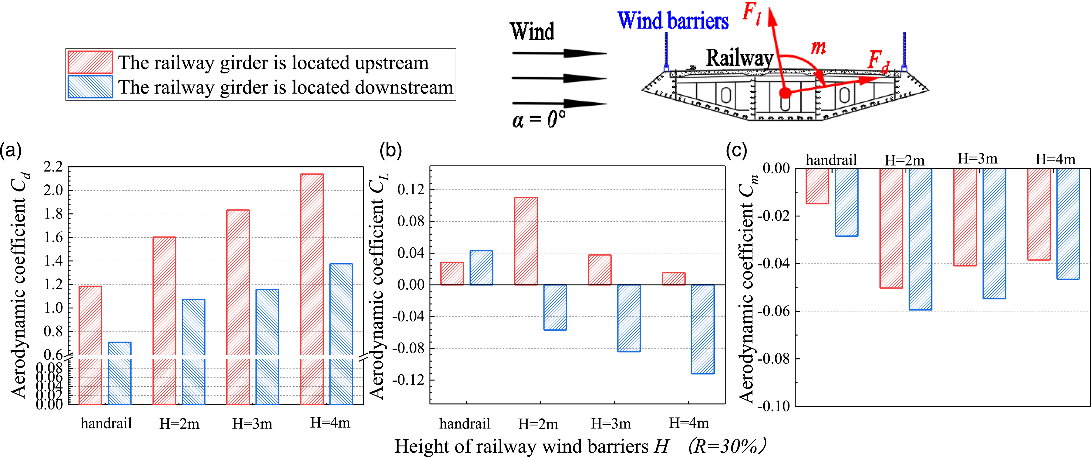
Although the aerodynamic shape of the highway girder has not changed, the installation of the railroad wind barrier will also affect the highway girder. As shown in Figure 14, when wind flows from the highway girder to the railway girder, the airflow acts on the highway girder first. Under different railway wind barrier heights, the drag coefficient, lift coefficient and torque coefficient of the highway girder are not the same. As the height of the downstream railway wind barrier increases, the drag coefficient of the upstream highway decreases, but the lift coefficient remains basically the same and the torque coefficient is 0. The influence of the railway wind barrier is can not be ignored. When the highway girder is located downstream, the airflow acts on the railway girder first. The upstream railway has a shading effect on the highway girder, which has a small drag coefficient. As the height of the railway wind barrier increases, the shading area becomes larger and the drag coefficient of the downstream highway girder increases gradually, while the values of lift coefficient and torque coefficient are smaller, they still show a certain trend of variation. The influence of railway wind barrier height also cannot be ignored. Aerodynamic coefficients of the highway girder.
Therefore, the influence law of railway wind barrier height on railway and highway girders are also slightly different, for example, the ventilation ratio of railway wind barrier has no influence on the drag coefficient of downstream highway girder, but the height still has an influence on it. Overall, the effect of wind barrier heights is slightly greater than wind barrier ventilation ratios.
Mean wind pressure coefficients of twin girders
The surface pressure distributions of the twin girders can reflect the detailed results of the influence of wind barriers on all surfaces of the highway and railway girder. As shown in Figures 15 and 16, the effect of different heights (H = 2 m, 3 m, 4 m) on the mean wind pressure coefficient is compared with wind barriers of R = 30% as examples when the railway girder is displaced upstream and downstream. C
P, mean
of twin girders (The highway girder is located downstream). (a) Upper surface (Pressure tap, No.1-33 of railway; Pressure tap, No.1-34 of highway). (b) Lower surface (Pressure tap, No.34-64 of railway; Pressure tap, No.35-84 of highway). C
P,
mean
of twin girders (The highway is located upstream). (a) Upper surface (Pressure tap, No.1-34 of highway, No.1-33 of railway). (b) Lower surface (Pressure tap, No.35-84 of highway, No.34-64 of railway).
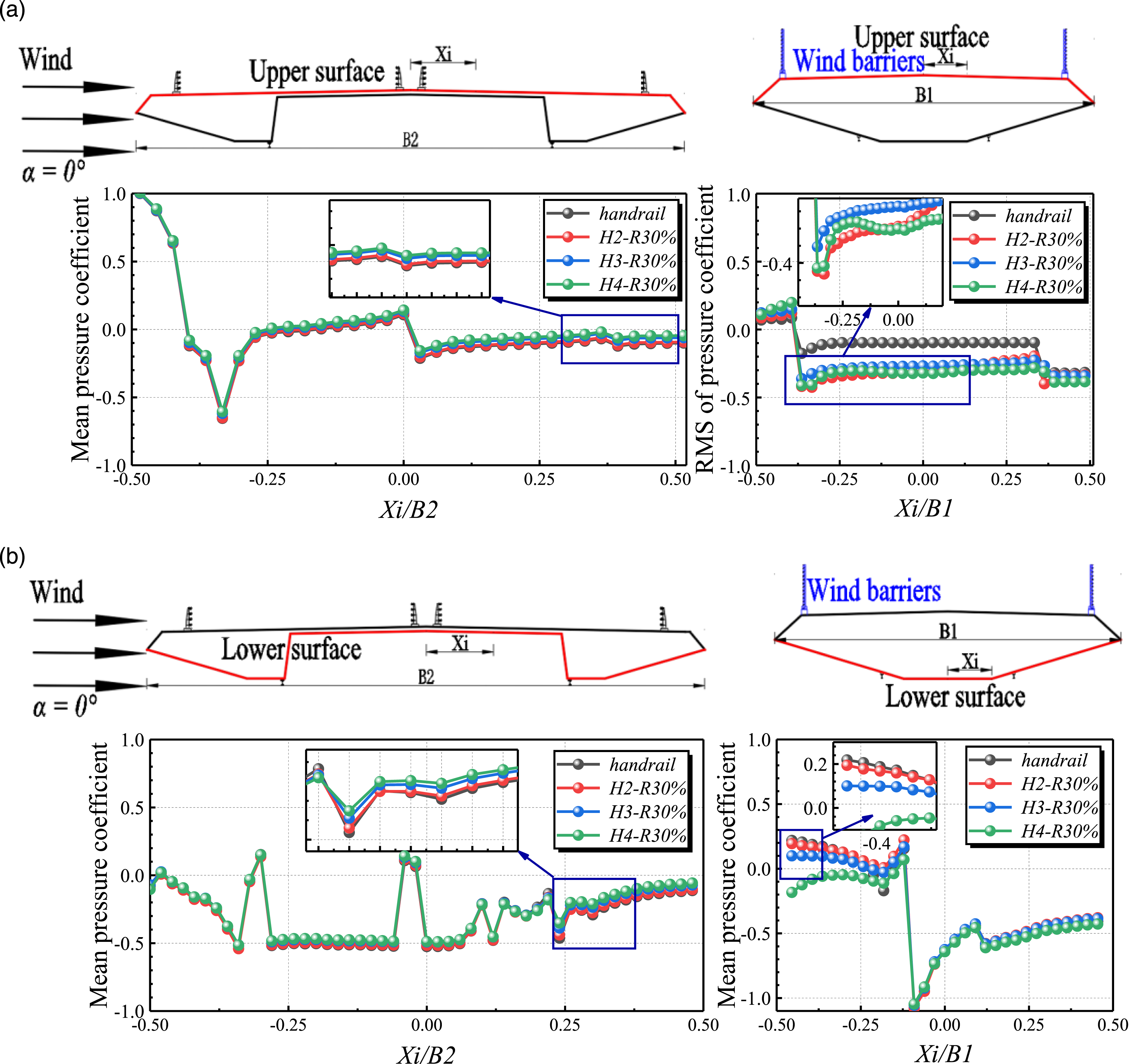
As shown in Figure 15, for the upstream railway, the airflow separation changes with the increase of wind barrier height, and the wind pressure coefficient in the positive pressure zone (Xi/B1 = −0.5 ∼ −0.25) shows the same trend, and the wind pressure coefficient in the negative pressure zone on the upper surface is basically the same. Xi/B represents the dimensionless horizontal coordinate of the pressure measuring hole. However, the windward side of the lower surface of the girder is affected, and the higher the height of the wind barrier, the larger the range of the negative pressure zone formed on the lower surface of the railway girder (see Figure 15(b)). While the negative pressure range on the lower surface of the girder also becomes significantly smaller when the height of the wind barrier is 2 m. For the downstream highway girder, which is shaded by the railway girder. And adjusting the wind barrier height of the upstream railway will cause a significant change in wake flow, which will have a greater impact on the downstream highway girder. As shown in Figure 15, when H = 2 m, positive pressure (Xi/B2 = −0.20 ∼ 0) appears in the upper surface area of the highway girder, which indicates that the downstream highway girder is not completely obscured by the upstream railway girder. When H = 3 m, the entire upper surface exhibits essentially negative pressure, which indicates that the downstream highway girder is completely obscured. And as the height of the wind barrier continues to increase to H = 4 m, the absolute value of the mean wind pressure coefficient on the upper surface of the highway girder continues to increase. Besides, the mean wind pressure coefficients on the lower surface of the highway girder under three different heights are basically the same, which are almost not affected by the wind barrier height.
When wind flows from the highway girder to the railway girder, the mean wind pressure coefficients on the surfaces of the twin girders are shown in Figure 16. For the downstream railway girder, which is shaded by the upstream highway girder, the positive pressure becomes smaller, and it shows a negative pressure area on the upper surface. After installing the wind barrier, the absolute value of wind pressure coefficient in the negative pressure area on the upper surface becomes larger, and the mean wind pressure coefficient on the lower surface is also affected, especially on the windward side of the railway girder (Xi/B1 = −0.5 ∼ −0.25). When the wind barrier height is H = 2 m and H = 3 m, the mean wind pressure coefficients on the upper and lower surfaces of the wind nozzle are positive. The wake flow did not separate at the wind nozzle and did not form a negative pressure zone on the lower surface of the railroad main beam. This is different from when the railway girder is located upstream where it is directly affected by airflow, that the air flow did not separate on the lower surface of the railway girder to form a negative pressure zone. However, when the wind barrier height increased to H = 4 m, a large negative pressure zone formed on the lower surface of the highway girder. The effect of wind barrier height is different from the effect of wind barrier permeability, which changes the trend of the mean wind pressure coefficient on the upper surface of the railway girder, and the mean wind pressure coefficient curves are not exactly the same. The windward side (Xi/B1 = –0.5 ∼ –0.25) of the lower surface of the railway girder is more affected by the height of the wind barrier, while the wind pressure on the leeward side of the lower surface is less affected (Xi/B1 = 0.25 ∼ 0.5), and the mean wind pressure coefficient values are almost the same. For the upstream highway girder, the airflow acts on the upstream highway girder first and is less influenced by the downstream railway wind barrier. Under different heights, only the mean wind pressure coefficient curves on the upper and lower surfaces of the leeward side area (Xi/B2 = 0.25 ∼ 0.5) do not completely overlap and are weakly affected, but the effect is much smaller when the highway girder is located upstream than when the highway girder is located downstream.
Therefore, the mean wind pressure coefficient of the upstream highway girder is not affected by the heights of the wind barrier along railway girder; the downstream highway girder is almost blocked by the upstream girder, but the degree of shielding is related to the height of the wind barrier, and the mean wind pressure coefficient is influenced by the height of the wind barrier. The mean wind pressure coefficients of the upstream railway girder are affected by the height of the wind barrier; the downstream railway girder is shielded by the upstream highway girder, but the shielding is incomplete, and a positive pressure area appears at the windward side of the downstream railway girder at the wind spout, and the windward side of the downstream railway girder is more affected by the heights.
Fluctuating wind pressure coefficients of twin girders
The fluctuating wind pressure coefficients on the surface of the upstream railway and the downstream highway girder are shown in Figure 17. As the height of the wind barrier increases, the peak fluctuating wind pressure coefficient gradually decreases and the pulsation becomes weaker. For the upper surface of the upstream railway girder (see Figure 18(a)), there is an area of airflow separation behind the windward wind barrier where the airflow pulsation is strong (Xi/B1 = −0.5 ∼ −0.25) because of a portion of the airflow separates at the top of the wind barrier. With the increase in height, the peak size of the pulsating wind pressure coefficient almost remained the same, but the position gradually moved to the wind nozzle, which was also related to the gradual reduction of the negative pressure area. For the leeward region of the lower surface (Xi/B1 = 0 ∼ 0.5), the fluctuating wind coefficients are basically the same and not affected by the wind barrier height. For the downstream highway girder (see Figure 17(a)), the upper surface of the highway girder is more affected and the fluctuating wind pressure coefficients on the lower surface are almost the same. When the height of wind barrier is H = 2m, the railway girder and wind barrier cannot completely cover the highway girder, and the pulsation on the upper surface of the highway girder is the strongest, and the fluctuating wind pressure coefficients on the upper surface gradually decreases as the height of wind barrier increases. C
P,
rms
of twin girders (The highway girder is located downstream). (a) Upper surface (Pressure tap, No.1-33 of railway, No.1-34 of highway). (b) Lower surface (Pressure tap, No.34-64 of railway, No.35-84 of highway). C
P,
rms
of twin girders (The highway girder is located upstream). (a) Upper surface (Pressure tap, No.1-34 of highway, No.1-33 of railway). (b) Lower surface (Pressure tap, No.35-84 of highway, No.34-64 of railway).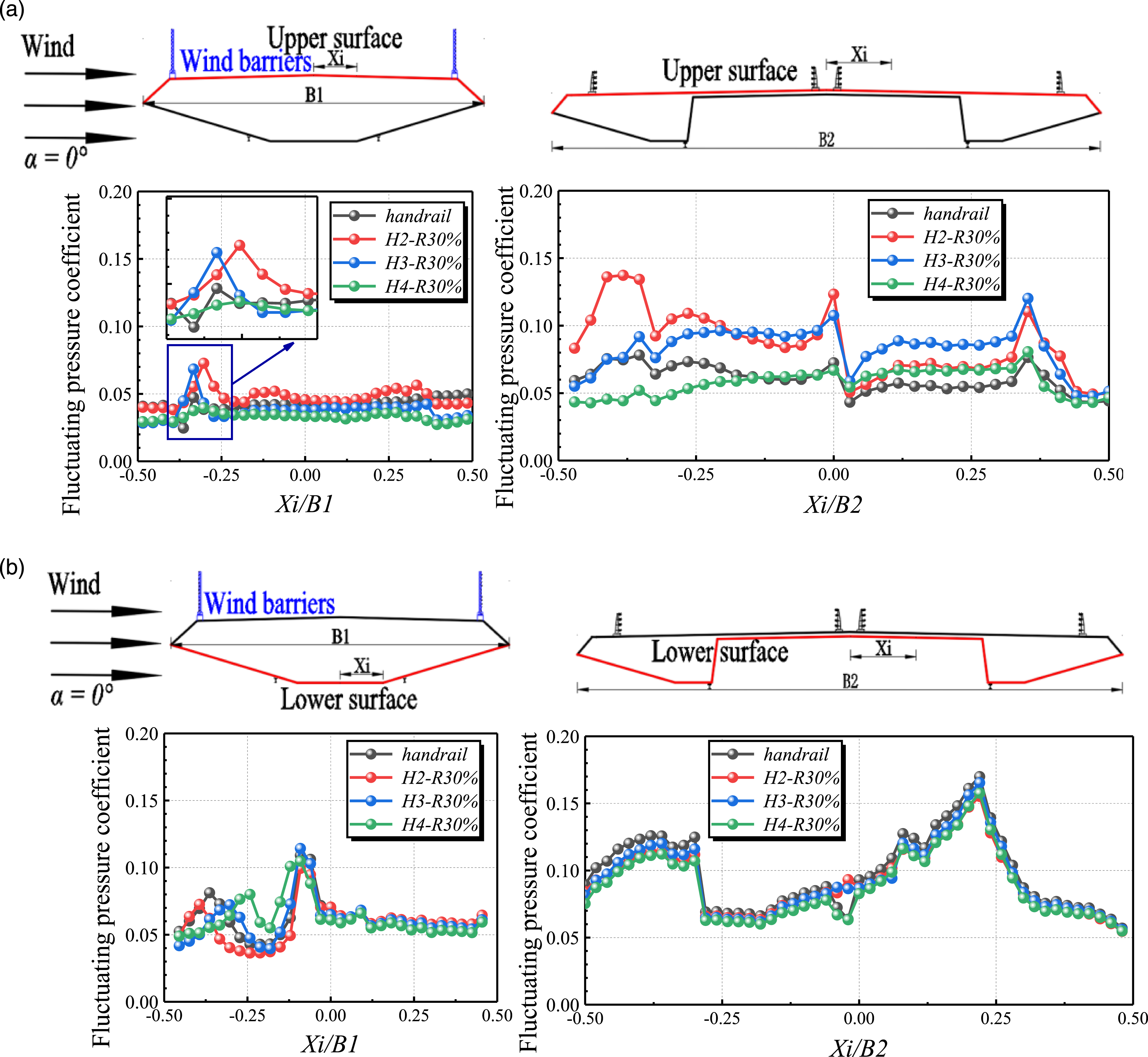
When wind flows from the highway girder to the railway girder, the fluctuating wind pressure coefficients on the surfaces of the twin girders are shown in Figure 18. For the upper surface of the downstream railway girder (Figure 18(a)), the peak of the fluctuating wind pressure coefficient on the upper surface appears at Xi/B1 = 0.25 on the leeward side of the railway and the pulsation on the upper surface is all stronger. As the height of the railway wind barrier increases, the peak fluctuating wind pressure coefficient gradually decreases and the pulsatility becomes weaker. The fluctuating wind pressure coefficient on the lower surface is basically the same and is not affected by the ventilation ratio of the wind barrier. For the upstream highway girder, under different railway wind barrier heights, the fluctuating wind pressure coefficients on the upper and lower surfaces are basically unchanged and are not affected by the wind barrier ventilation ratio.
Therefore, the fluctuating wind pressure coefficients of the upstream highway girder is not affected by the heights of wind barriers along railway girder; as the height of the upstream railway wind barrier increases, the fluctuating wind pressure coefficient of the downstream highway girder gradually becomes smaller. The fluctuating wind pressure coefficient of the upstream railway girder on the upper and lower surfaces affected by the height of the wind barrier; the fluctuating wind pressure on the lower surface of the downstream railway girder is not affected by the height of wind barrier, but the fluctuating wind pressure coefficient on the upper surface is obviously affected by the height of the wind barrier, and the pattern is completely different from that of the railway girder located upstream.
Conclusion
In the present study, the aerodynamic performance of twin-separated parallel girders with various wind barriers clamped at railway girder were studied by static segmental model wind tunnel tests. The conclusions are as follows: (1) The aerodynamic coefficients of highway and railway girders are affected significantly by the incoming wind direction, which must be considered. The height and ventilation ratio of the railway wind barriers has an effect on aerodynamic coefficient, but the laws are not the same due to the aerodynamic interference effect of the twin girders. (2) The height and ventilation ratio of the railway wind barriers have an effect on aerodynamic coefficients when the railway is located upstream and downstream, but the laws are not the same due to the aerodynamic interference effect. Besides, the adjacent highway girders are also affected by the height and ventilation ratio of wind barriers along railway girder. (3) The mean wind pressure coefficients of the railway girder located upstream and downstream are both influenced by the ventilation ratio and height of wind barriers. For the downstream railway girder, the highway girder partially shades it, and positive pressure appears at the windward side of its wind nozzle, and the windward side is more influenced by the wind barriers. The fluctuating wind pressure coefficients on the upper and lower surfaces of the upstream railway girder are influenced by the ventilation ratio and height of wind barriers, and the fluctuating wind pressure coefficients on the lower surface of the downstream railway girder are not influenced by the wind barrier, but the fluctuating wind pressure coefficients on the upper surface is obviously influenced by the height of the wind barrier, and the law is completely different from that of the railway girder located upstream. (4) The mean wind pressure coefficient and fluctuating wind pressure coefficients of the upstream highway girder are almost not affected by the ventilation ratio and height of wind barriers along railway girder. However, For the downstream highway girder, it is almost blocked by the upstream railway girder, and the surface shows negative pressure, and the mean wind pressure coefficients are less affected by the ventilation ratio of wind barriers, but the fluctuating wind pressure coefficients of the downstream highway girder gradually becomes smaller as the ventilation ratios increases. The mean wind pressure coefficients on the surface of the downstream highway girder are influenced by the height of wind barrier, and the fluctuating wind pressure coefficient of the downstream highway girder gradually becomes smaller as the height of wind barrier increases. (5) It is worth noting that wind barrier parameters along railway girders should be recommended to satisfy the requirements of the twin girders after a comprehensive evaluation for twin-separated parallel decks. The suggestion “the aerodynamic interference effect of the twin parallel bridge must be considered when setting up the wind barrier” should be incorporated in the design guidelines.
Future studies should investigate: - Effects of more parameters, such as wind barrier patterns, layout, curvatures and so on. - Flow distribution around twin girders by Particle Image Velocimetry and Computational Fluid Dynamics. - Whether results vary when installing wind barriers on highway bridges.
Footnotes
Acknowledgements
This study is sponsored by the National Natural Science Foundation of China (Nos. 52078504, 51822803, 51925808) and the Science and Technology Innovation Program of Hunan Province (No. 2021RC3016), the Natural Science Foundation of Hunan Province (2022JJ10082), the Fundamental Research Funds for the Central Universities of Central South University (CX20220238, 2022ZZTS0152), which are gratefully acknowledged.
Declaration of conflicting interests
The author(s) declared no potential conflicts of interest with respect to the research, authorship, and/or publication of this article.
Funding
The author(s) disclosed receipt of the following financial support for the research, authorship, and/or publication of this article: This study is sponsored by the National Natural Science Foundation of China (Nos. 52078504, 51822803, 51925808) and the Science and Technology Innovation Program of Hunan Province (No. 2021RC3016), the Natural Science Foundation of Hunan Province (2022JJ10082), the Fundamental Research Funds for the Central Universities of Central South University (CX20220238, 2022ZZTS0152).