



Abstract
The excessive loss of vertical prestress is a primary factor contributing to web cracking in large-span prestressed concrete box girders. The self-prestressing characteristics of iron-based shape memory alloys (Fe-SMAs) after heat activation offer significant potential for the timely and efficient supplementation of vertical prestress loss. Therefore, the effects of stress supplementation introduced by the self-prestressing of Fe-SMA rebars were investigated using six scaled concrete plates. This analysis focuses on the influence of the vertical prestressing rebar type and spacing on the compressive stress field. The self-prestressing of the Fe-SMA rebars stabilized after approximately 4 h of Fe-SMA activation. Furthermore, unlike the conventional prestressing rebar, the self-prestressing of the Fe-SMA rebar was relatively uniformly distributed along its entire length. When both types of bars were positioned at the same position in separate specimens, the difference between the maximum and minimum values of stress on the specimen with only Fe-SMA rebars was only 6.98% of that in the specimen with only screw-threaded steel bars. Overall, by strategically and vertically equipping the web with Fe-SMA rebars, the vertical prestress loss of the box web can be effectively supplemented in a timely manner.
Highlights
The effects of stress supplementation introduced by the self-prestressing of Fe-SMA rebars were investigated. The self-prestressing of the Fe-SMA rebars stabilized after approximately 4 h of Fe-SMA activation. The self-prestressing of the Fe-SMA rebar was relatively uniformly distributed along its entire length.
Introduction
Prestressed concrete (PC) box girder bridges are highly competitive bridge structures (Pan and You, 2015; Zhong et al., 2011). Its advantages include excellent crossing ability, large torsional and sectional flexural stiffness, and good integrity. However, PC box-girder bridges in service typically exhibit varying degrees of cracking, with web cracks being one of the most prevalent and dangerous issues (Shao et al., 2011; Wang et al., 2008; Yuan et al., 2015; Zhang and Yao, 2012). By appropriately placing prestressed rebars, the web can maintain bidirectional compression under the combined action of longitudinal and vertical prestresses, thereby delaying the emergence of web cracks.
Through previous technical measurements and theoretical research, it was revealed that the vertical prestress has a substantial impact on the principal tensile stress of the web (Fang and Wang, 2006; Xu and Wu, 2015). However, box webs often exhibit varying degrees of cracking owing to the frequent and unavoidable loss of vertical prestress (Shao et al., 2014). The loss of vertical prestress can be divided into the instantaneous loss of the tensioning anchorage and the loss during long-term service. Owing to the limited length of vertical prestressed steel bars, the instantaneous loss caused by anchorage deformation and retracted steel rebars exceeds 50% of the total loss (Fang and Wang, 2006). Currently, methods to solve instantaneous loss include using high-strength vertical prestressed rebars (Zheng and Fang, 2014), changing the tensioning sequence (Wang et al., 2020), over-tension, and double-tension (Shao et al., 2014; Zhang et al., 2021). Numerous researchers (Shen et al., 2009; Wu et al., 2021; Yin, 2020; Zhao, 2012; Zhao et al., 2011; Zhao and Peng, 2004) have investigated web prestress diffusion under single and multiple vertical prestressed tendons to ascertain the ideal layout spacing for vertical prestressed rebars. However, no effective method can actively compensate for the prestress loss during long-term service. Existing methods include active techniques such as external prestressing (Park et al., 2005; Qi et al., 2020; Song and Song, 2017; Ye et al., 2018), as well as passive techniques such as bonding steel plates (Rakgate and Dundu, 2018), adhering carbon fiber reinforced polymer (CFRP) plates (Fang and Wu, 2019; He et al., 2020; Lee et al., 2017; Miruthun et al., 2021; Wang and Zhou, 2018; Zhu et al., 2019), and enhancing cross-sections. However, these strengthening methods are not used until irreversible damage, such as visible cracks, occurred in the structure.
In recent years, the adoption of novel materials and technologies in bridge construction has increased. However, the previously mentioned methods still cannot effectively solve web cracking. Therefore, a method that can promptly and efficiently compensate for the loss of vertical prestressing on web plates during service is urgently needed. Subsequently, the treatment of web cracking can be transformed from a conventional severe cracking remediation mode to a timely prevention and compensation mode. This will help to prolong the service life of concrete box girder bridges and enhance their overall service performance. The quick self-prestressing characteristics of shape memory alloys (SMAs) by activation heating could provide sufficient possibilities for addressing the aforementioned issues. Compared to conventional prestressing, the prestressing generated by SMAs is far more intelligent, as it continuously generates “self-prestressing” in the length direction of the rebars without experiencing any prestressing losses from friction or anchorage (Zhu et al., 2022b). The application concept of SMA in the web of box girder bridges (Liu et al., 2022): apart from the tensioning process, SMA rebars can adopt the same construction method as the vertical screw-threaded steel bar. The resistive heating was achieved by connecting power lines at the ends of the SMA rebars in advance, thereby generating self-prestress. Owing to their high cost, the widespread application of traditional nickel–titanium-based SMAs (NiTi-SMAs) in civil engineering is limited. Recently, a novel form of iron-based SMA (Fe-SMA) has attracted significant attention (Dong et al., 2009).
Currently, the application of Fe-SMAs in strengthening of existing concrete structures has been extensively explored, demonstrating significant enhancement in enhancing structural performance. Research consistently indicates that near-surface mounted (NSM) Fe-SMA strips or rebars substantially improve the flexural capacity of reinforced concrete beams (Czaderski et al., 2014; Hong et al., 2018; Shahverdi et al., 2016b). Similar benefits extend to fatigue resistance and durability (Rojob and El-Hacha, 2018a, 2018b). Furthermore, embedding Fe-SMA in the shotcrete layer has been demonstrated to concurrently enhance both shear and flexural performance of beams (Czaderski et al., 2021; Shahverdi et al., 2016a). Beyond beams, Fe-SMA reinforcement in concrete slabs has also been validated, where the induced prestress significantly increases cracking and yield loads while preserving structural ductility (Schranz et al., 2021). In external reinforcement applications, comparative studies (Qiang et al., 2024) indicate that Fe-SMA strips demonstrate superior performance to CFRP plates in enhancing beam stiffness and flexural capacity when mechanically anchored.
Beyond strengthening applications, Fe-SMA holds significant potential as an active reinforcement material in new construction. Research indicates that embedding Fe-SMA rebars or stirrups within beams or slabs can effectively reduce crack formation, increase cracking load, and enhance shear capacity following thermal activation (Hong et al., 2022a, 2023; Ji et al., 2022; Yeon et al., 2022). The critical factor for practical application lies in the bond performance between Fe-SMA materials and concrete. Protective methods through innovative component design (such as employing plastic corrugated pipes and high-temperature-resistant mortar) can mitigate concrete damage during heating while maintaining high bond strength post-activation (Liu et al., 2022, 2023). This enables Fe-SMA materials to effectively delay cracking in components like T-beams (Liu et al., 2024). The multifunctionality of Fe-SMA materials is further demonstrated by: resolving cracking issues in prestressed anchorage zones (Ji et al., 2023); enhancing compressive strength and ductility in concrete columns through spiral-wrapped confinement (Yeon et al., 2024); and even functioning as self-positioning components or energy dissipators in seismic applications (Hu et al., 2024; Vahedi et al., 2024; Wang et al., 2022; Wang and Zhu, 2022), thereby reducing residual displacement.
A growing number of studies highlight the unique advantages of iron-based shape memory alloys (Fe-SMAs) in supporting these diverse applications. The shape memory effect generates significant recovery stresses (typically 300 MPa ∼ 400 MPa) upon thermal activation, supporting the fundamental ‘self-prestressing’ mechanism. Compared with NiTi-SMA materials, Fe-SMA are mainly composed of inexpensive elements such as iron, manganese and silicon (Dong et al., 2009). The low material cost is crucial for large-scale civil engineering projects. Furthermore, although the cost of Fe-SMA steel bars is higher than that of ordinary steel bars, its cost advantage throughout the entire lifecycle is very significant. The traditional methods for compensating for prestress losses usually require complex processes such as external prestress or installing steel plates, which have long construction periods and require traffic interruption. However, the Fe-SMA technology only requires portable power equipment, has a fast construction speed, and can be repeatedly activated, thereby significantly reducing operating and maintenance costs. Taking the concrete box girder bridge of Nan Shao River in China as an example (Liu et al., 2022), the effect of using Fe-SMA to offset prestress losses was calculated and analyzed. The results show that using the Fe-SMA could offset the vertical prestress loss and maintain an effective vertical prestress ratio of over 95% for nearly 30 years of service life. The maximum principal tensile stress only increased by 50% of the initial principal tensile stress.
The cracking of the web is influenced by multiple factors, including vertical prestress, longitudinal prestress, and temperature-induced stresses. Directly studying the crack resistance performance of full-scale box girder webs under such complex, multi-factor conditions may not allow precise evaluation of the individual effects of each influencing factor. The primary objective of this study is to investigate whether arranging Fe-SMA rebars between the posttensioned screw-threaded steel bar can compensate for vertical prestress loss by generating self-prestress through activation during the service period. To this end, six concrete thin plate specimens, as illustrated in Figure 1, were designed and fabricated for laboratory testing to replicate the stress conditions of an actual bridge box-girder web under vertical prestress. The prestress loss was simulated by varying the tensile force of the posttensioned screw-threaded steel bar and activating the Fe-SMA to investigate the stress supplement effect. This provides experimental verification and a reference for the application of Fe-SMA rebars in long-span PC box girder bridges. The placement of Fe-SMA rebars in the web of large-span prestressed concrete box girders.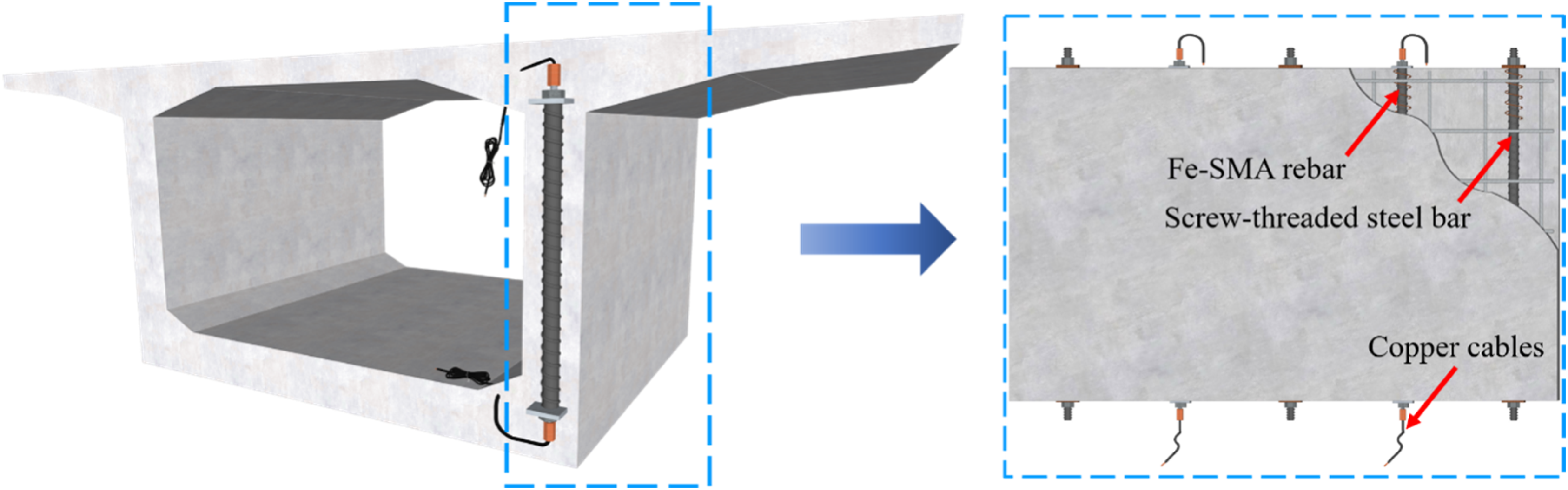
Materials
Rebars
Fe-SMA rebar
The Fe-SMA rebar with a nominal diameter of 10 mm used in the study is shown in Figure 2(a), which was produced by FuSteel CO., LTD., China. The elemental composition (in wt%) of the Fe-SMA was Fe-15.6Mn-4.9Si-9.9Cr-3.9Ni-1.2V-0.2N-0.01C. The recovery stress test equipment is displayed in Figure 2(b) (Dong et al., 2023). The Fe-SMA rebar was connected to a high-current power supply device through a copper clamp for heating, and the temperature variations of each component during heating and cooling were recorded using an infrared camera. The recovery stress generated by the Fe-SMA rebar during the test process was obtained by reading the load sensor using DH2002 data acquisition equipment. With the increase of heating temperature, the bonding force between Fe-SMA rebars and cement mortar all gradually decreased (Liu et al., 2023). Meanwhile, higher activation temperatures require higher power from the power supply, especially when the Fe-SMA rebar is long. Therefore, after testing the stress recovery performance of the Fe-SMA rebar, this study selected the Fe-SMA rebar with a prestrain of 6% and a heating activation temperature of 200°C for the following concrete thin plate reinforcement (Sun et al., 2024). Table 1 lists the measured mechanical characteristics and stress recovery of the 6% prestrained Fe-SMA rebar. Fe-SMA rebar and test device: (a) Fe-SMA rebar; (b) Recovery stress test equipment. Mechanical properties and recovery stress at 200°C of Fe-SMA rebars with 6% prestrain. Note. The proof stress of 0.2% (σy,0.2) is the stress related to the plastic elongation of 0.2%. The stress range for the elastic modulus is 50 MPa to 200 MPa. The calculated diameter is 9.7 mm, which is the actual diameter after pre-straining.

Steel rebars
A screw-threaded steel bar with a diameter of 15 mm was used as a conventional vertical prestressed bar, which exhibited a yield strength of 830 MPa. Ordinary rebars comprise crack-resistant rebars and spiral stirrups. Spiral stirrups were positioned at both ends of the plastic corrugated pipes to prevent cracking beneath the anchor when prestress was applied. Each stirrup had five rings, each with a diameter of 10 mm, a spacing of 45 mm, an inner diameter of 110 mm, and a strength rating of 300 MPa grade hot-rolled plain (HPB300) steel bar. The crack-resistant rebar was a 500 MPa hot-rolled ribbed (HRB500) steel bar with a diameter of 8 mm, organized in a double-layer, two-way configuration with a spacing of 500 mm.
Concrete and grouting mortar
Commercial concrete with an expected strength of 55 MPa was used. The 150 mm × 150 mm × 150 mm concrete cubes were cured under the same conditions as the concrete plate at the same time as the experiment. Their compressive strength was measured to be 55 ± 2 MPa.
Plastic corrugated pipes were filled with Sika mortar. The type of cement mortar used was Sika Grout® ES, which exhibited excellent bonding capabilities and high-temperature resistance. The compressive strength of the 100 mm × 100 mm × 100 mm cube specimens was 73 ± 1 MPa on the day of the experiment.
Experimental program
Specimen size and test parameters
Six rectangular concrete thin plates (length × width × thickness = 2500 mm × 1500 mm × 150 mm) were fabricated to simulate a reinforced concrete box web. The specimens were designed under the principle of maintaining a compressive stress of 3–4 MPa (Shen et al., 2009), which is the normal vertical compressive stress range of a web section. The prestressed rebars of the specimens were placed in plastic corrugated pipes with a diameter of 50 mm and filled with Sika mortar. The prestressed rebars consisted of screw-threaded steel and Fe-SMA, with the latter arranged in five plates. Based on the research results of Liu (Liu et al., 2023), the activation temperature and time were set to 200°C and 30°s.
In this study, two different configuration specimens were designed: one equipped with only Fe-SMA rebars and the other combined equipped with Fe-SMA rebars and screw-threaded steel bars. The sizes and details of the specimens are illustrated in Figure 3 and Table 2, respectively. The specimens were labeled using two distinct elements representing different parameters. The first element denotes the type of prestressed rebar, and the second element denotes the spacing of the prestressed bars. For example, “F-250” represents a plate with Fe-SMA rebars as prestressed rebars, with a 250 mm distance between each Fe-SMA rebar. Layout of specimens with Fe-SMA rebars only (unit: mm): (a) F-500; (b) F-250. Test parameters of specimens with Fe-SMA rebars only.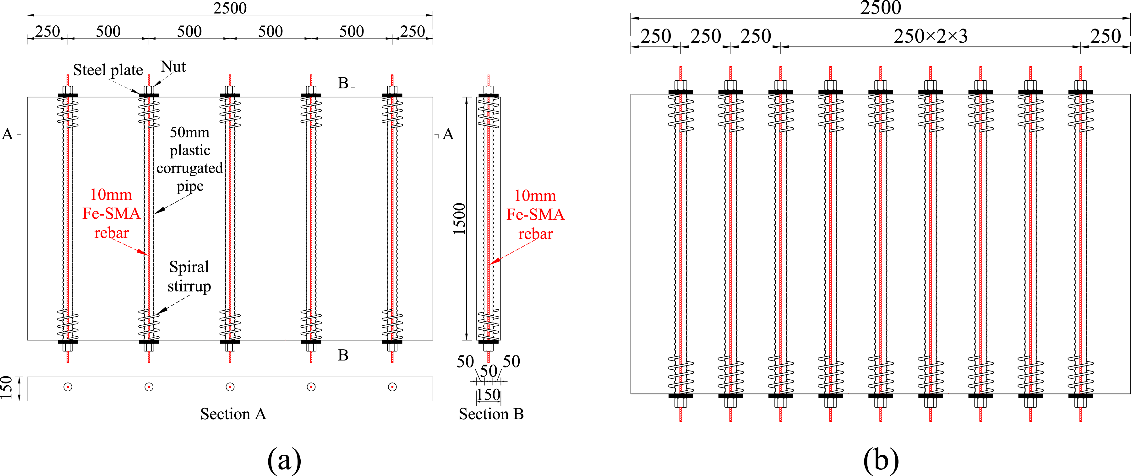

The other four plates were designed to compensate for the prestress loss of the screw-threaded steel bar using the prestress generated by the Fe-SMA rebar. To replicate the vertical prestress losses of 0%, 20%, 40%, and 60% in the screw-threaded steel bar, design tensions of 100%, 80%, 60%, and 40%, respectively, were maintained. Fe-SMA rebars (0, 1, 2, and 3) were placed between two screw-threaded steel bars. Details of the specimen parameters are presented in Figure 4 and Table 3. In the sample numbering scheme, the first element denotes the type of prestressed rebar, the second denotes the percentage of prestress loss in the screw-threaded steel bar, and the third denotes the number of Fe-SMA rebars between two screw-threaded steel bars. For instance, SF-60%-3 denotes a plate equipped with screw-threaded steel bars with a 60% prestressing loss and three Fe-SMA rebars sandwiched between each pair of screw-threaded steel bars. Layout of specimens with mixed configurations of Fe-SMA rebars and screw-threaded steel bars (unit: mm): (a) S-0%-0; (b) SF-20%-1; (c) SF-40%-2; (d) SF-60%-3. Test parameters of specimens with mixed configurations of Fe-SMA rebars and screw-threaded steel bars.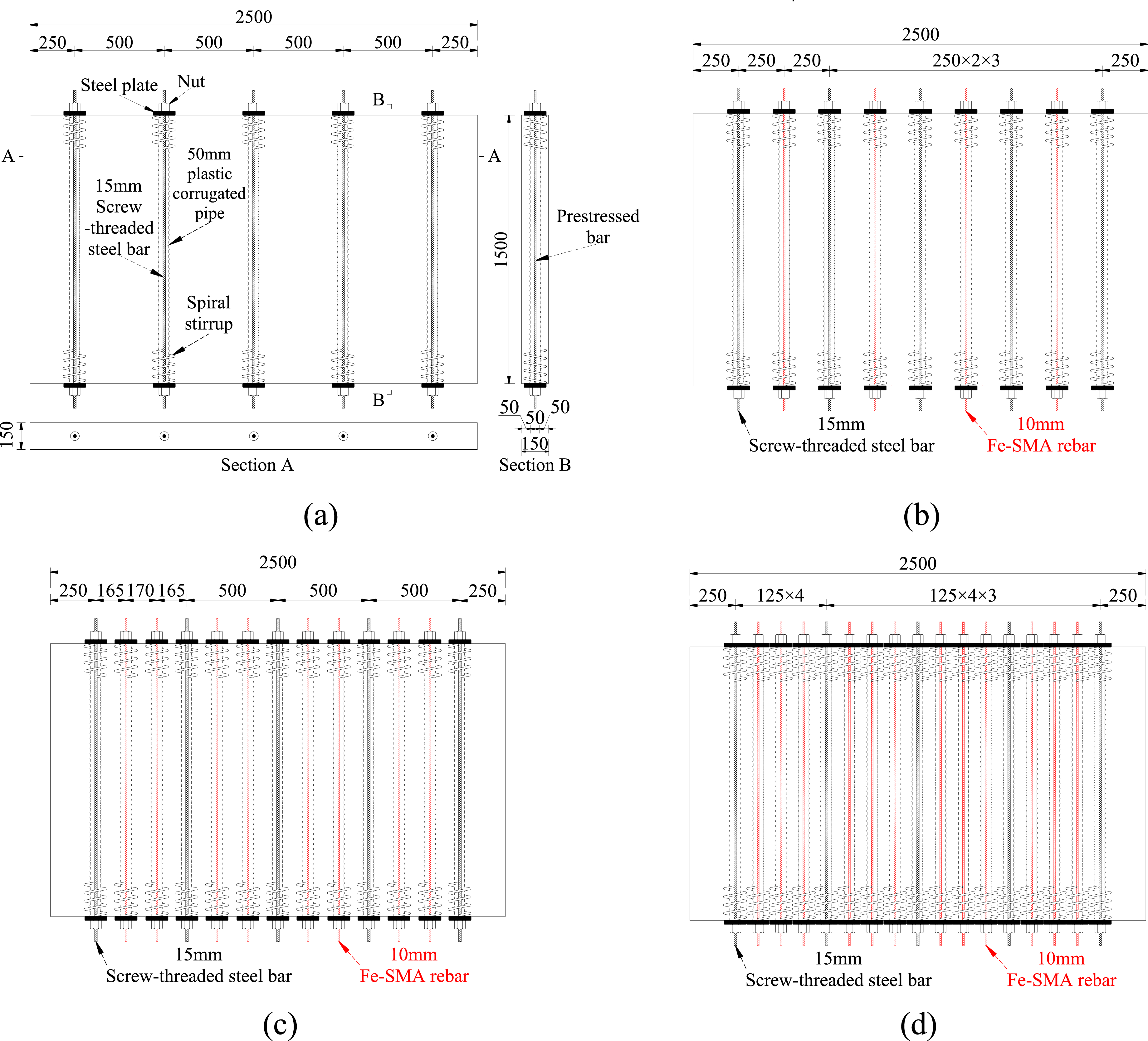

Specimen preparation
Specimen fabrication process
Preparation of Fe-SMA rebars
The Fe-SMA rebar was tensioned to 6% prestrain on a 6 m steel platform, cut to the required length, and threaded on both ends. Figure 5(a) shows a schematic of the tensioned platform. Two thermocouples were fixed at 1/3 and 2/3 of the length of the Fe-SMA rebar to monitor the temperature during activation process. Specimen preparation: (a) Fe-SMA rebar pre-straining; (b) Prepared formwork; (c) Casting of concrete.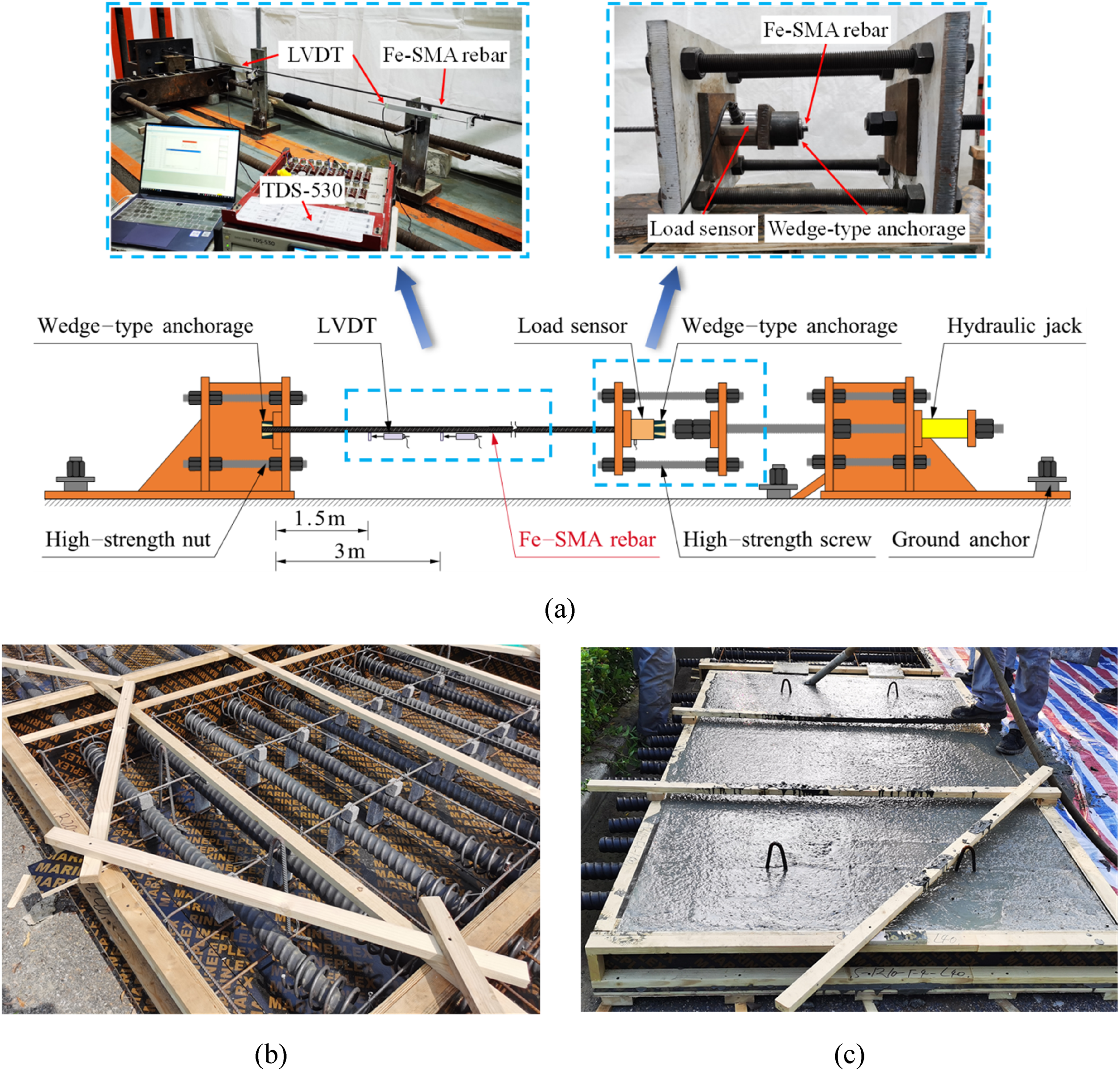
Concrete casting
After placing the steel cage in the wooden formwork, it was supported by a concrete pad to ensure that the protective layer of the concrete was 20 mm thick. Following the required cutting length, the plastic corrugated pipe was threaded into the designated hole of the wooden formwork, and the spiral stirrups were fastened to the steel cage. Figure 5(b) and (c) show the prepared formwork and casting of the concrete, respectively.
Grouting mortar
Two different grouting cases were considered for the prestressed bars of the specimens. Plastic corrugated pipes equipped with Fe-SMA rebars were grouted after 65 days of concrete pouring and curing. Given the requirement for on-site tensioning of screw-threaded steel bars, grouting was completed following a 28-day curing period of Fe-SMA grouting and tensioning of the screw-threaded steel bars. During the grouting procedure, the specimen was turned from a horizontal to a vertical position, and the rebars were positioned in the middle of the plastic corrugated pipes. Subsequently, uniformly mixed Sika mortar was poured from the top of the corrugated pipes.
Strain gauge position
An array of strain gauges was positioned on the surface of the concrete plate to measure the stress field. Strain gauges were arranged in an 8 × 11 matrix configuration. Eight rows of strain gauges were arranged along the width direction of the plate to measure transverse stress gradients resulting from the stress diffusion effect of vertical pre-stressing rebars. Monitoring these positions facilitates quantitative evaluation of the suggested stress diffusion angles (26°, 36°, and 46°, etc.) and identifies probable stress concentration zones next to the tendon anchoring: One row was positioned in the center of the web, four rows were arranged at the tension end at 100 mm intervals, and three rows were positioned at heights of 26°, 36°, and 46° diffusion angles in the anchorage section. Eleven columns of strain gauges were arranged along the specimen’s length. The stress was concentrated near the center position; therefore, nine columns of strain gauges were arranged at a spacing of 125 mm, only one column was arranged in the middle of the two screw-threaded steel bars on both sides. Figure 6 illustrates the precise location and quantity of strain gauges. Layout of strain gauges: (a) Schematic (unit: mm); (b) Photograph.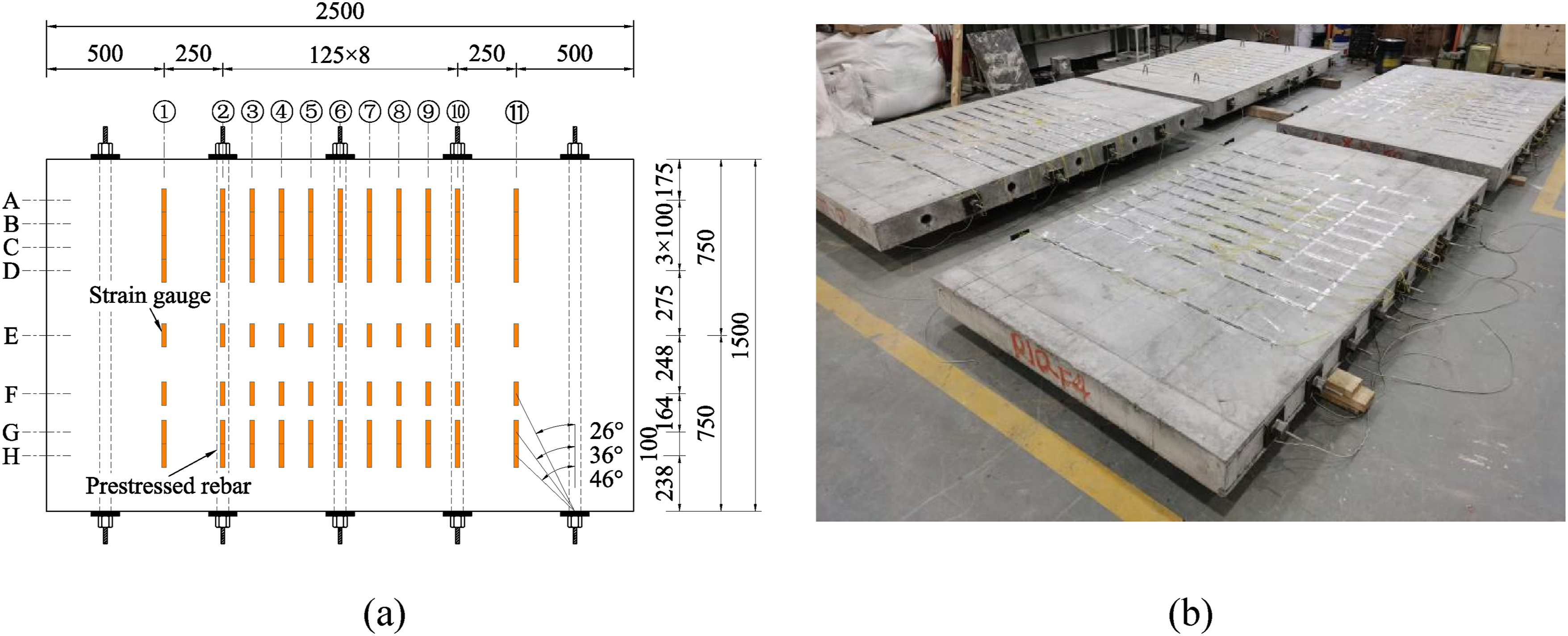
Application of prestress
The screw-threaded steel bar was tensioned following a 40-day curing period for the Fe-SMA grout. Before the tensioning, the nuts at both ends of the rebar were tightened to ensure that the steel pad and screw-threaded steel bar were located in the middle of the pipes. According to the degree of prestress loss of 0%, 20%, 40%, and 60%, respectively, the corresponding controlled tensile force (stress) were 141 kN (800 MPa), 113 kN (640 MPa), 85 kN (480 MPa), and 56.4 kN (320 MPa). During the tensioning process, the through-hole used load sensors to monitor the tension force in real time, ensuring that the tensioning accuracy was within ± 2%. During tensioning, the acquisition device TDS-530 connected to the strain gauge collected the surface strain at a rate of 2 s, as shown in Figure 7(a). Process of applying prestress: (a) Tensioning of the screw-threaded steel bar; (b) Activation of the Fe-SMA rebar.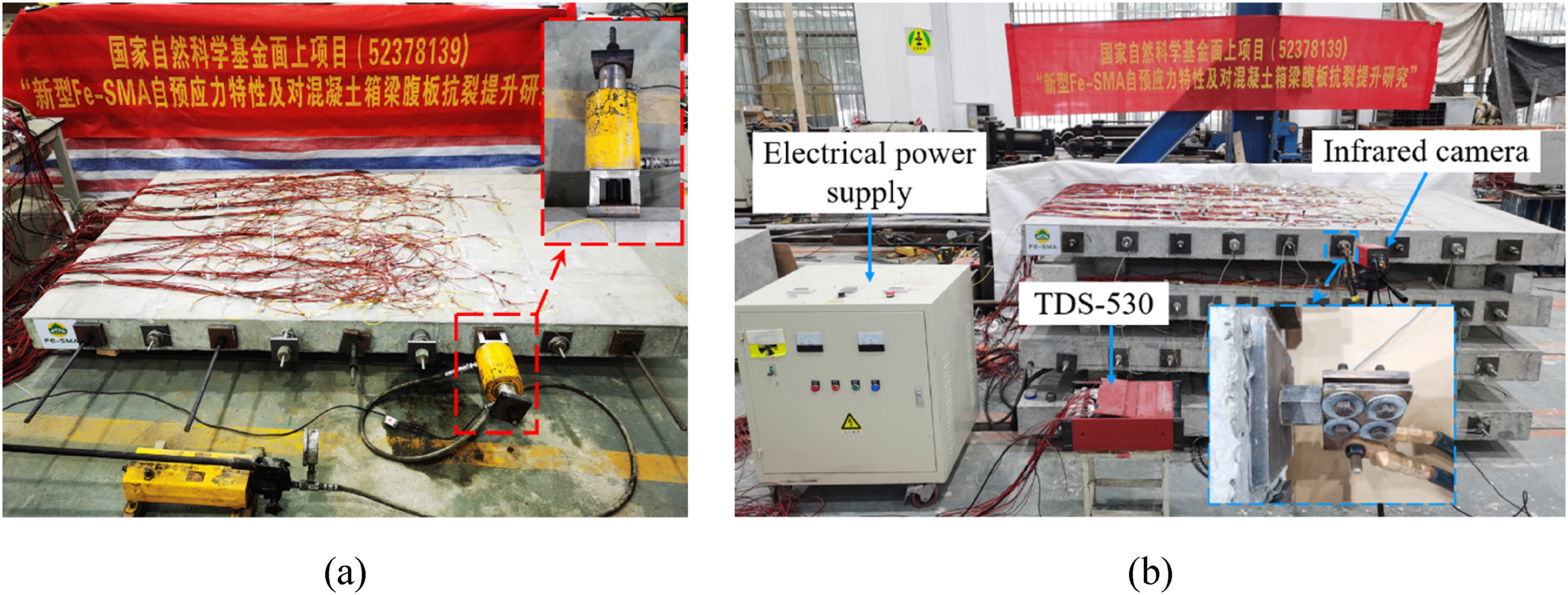
Resistive heating of the Fe-SMA rebar was performed using a self-developed electrical power supply with a rated power of 60 kW, as shown in Figure 7(b). Both ends of the Fe-SMA rebar were clamped using a copper clamp to attach them to the activated device. The Fe-SMA was rapidly heated to 200°C, referencing the activation current associated with 200°C and 30 s as outlined in the research by Liu et al. (Liu et al., 2023) and the activation guideline paper by Zheng et al. (Zheng et al., 2024). The self-developed electric activation device utilized in this experiment accurately exhibited the current magnitude to allow real-time monitoring and ensure a constant current density. Simultaneously, during the electrical activation, the temperature was steadily raised by 13°C every 2 s to achieve 200°C within the designated timeframe. Owing to the postponement in the data acquisition by the thermocouples, the power supply was immediately stopped when the TDS-530 indicated that the Fe-SMA temperature reached 190°C, ensuring that the actual temperature of the Fe-SMA stabilized around 200°C after heating cessation. The heating process was terminated when either of the two thermocouples reached 200°C, which was defined as the criterion for the Fe-SMA to attain the target temperature of 200°C.
The temperature and strain were recorded using an acquisition device TDS-530. The surface temperature of the copper clamp was measured by using an infrared camera. The data acquisition rate of the TDS-530 and the infrared camera was 2 s to guarantee simultaneous recordings. The Fe-SMA rebars in this study were not only embedded in high-strength sika mortar but also equipped with nuts at both ends. The combined impact of the mortar’s bonding force and the nuts effectively controlled interfacial slip between the Fe-SMA rebars and concrete, thereby effectively reducing possible prestress losses.
Results and analysis
Temperature field of specimens
Surface temperatures of the concrete, nut, steel plate, and exposed end of the Fe-SMA rebar were monitored using an infrared camera. The temperature of the Fe-SMA rebar pre-embedded in the concrete was measured using thermocouples. Figure 8 shows the infrared camera images and temperature-time relationship curves during the rising and cooling processes in typical specimen F-250. A current density of 8.28 A/mm2 was employed to activate the Fe-SMA rebars throughout the test to reduce the bonding damage to the concrete and Sika mortar in the corrugated pipes caused by activation (Dong et al., 2023). Figure 8 shows that after 30 s of electrification, the Fe-SMA rebar in the specimen could achieve the desired temperature of 200°C. The temperature of the concrete surface was 7.7°C, whereas that of the nut was 80.2°C. The concrete surface temperature only varied by 2.9°C throughout the whole heating and cooling operation, from an initial 7.3°C to 10.2°C. The steel plate and the nut had different temperatures of 10.5°C and 74.1°C, respectively. This demonstrates that, in contrast to the temperature variation range of the other parts, the temperature difference of the concrete during the heating and cooling processes was small. This suggests that using a high current for resistance activation can not only effectively and swiftly complete the activation of the Fe-SMA rebar but also prevent the concrete from experiencing excessive temperature stress. Variation in temperature at various locations with time: (a) Temperature versus activation time curves of the representative F-250 specimen; (b) Infrared camera images.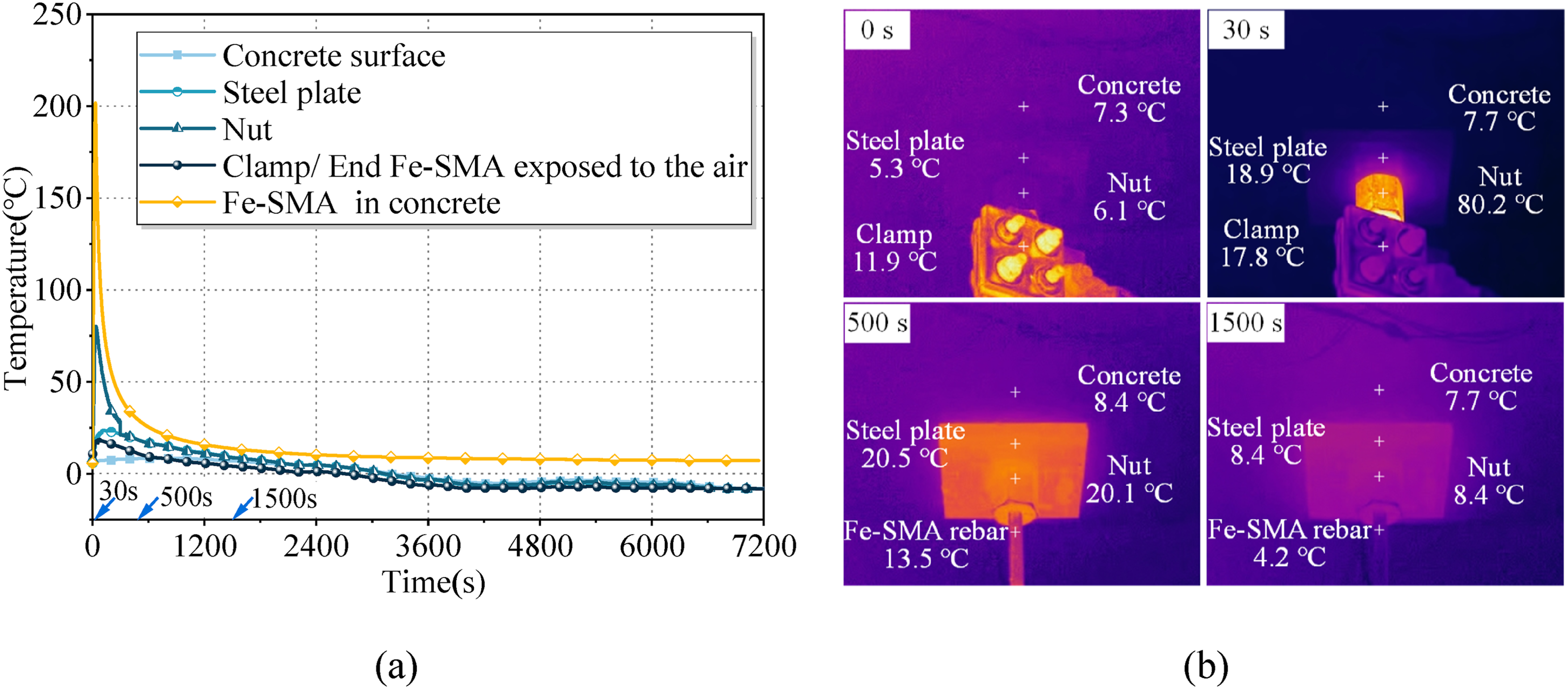
Variation of stress with time and location following the activation of the Fe-SMA rebar
In contrast to steel strands or threaded bars that provide immediate prestress, Fe-SMA necessitates thermal activation through a heating and cooling process. Since Fe-SMA rebars were embedded in concrete, heat transfer during activation first caused thermal expansion to the concrete, followed by compressive stress after cooling. Activating one Fe-SMA rebar (including activation and clamp replacement) took approximately 5 min. Specimen SF-40%-2 was observed over a 12-h period, with Figure 9 illustrating the stress evolution along horizontal lines A/E and vertical lines 2/3, thereby validating this thermo-mechanical behavior. Stress variation curves of SF-40%-2 specimens within 12 h: (a) Line A; (b) Line E; (c) Line 2; (d) Line 3.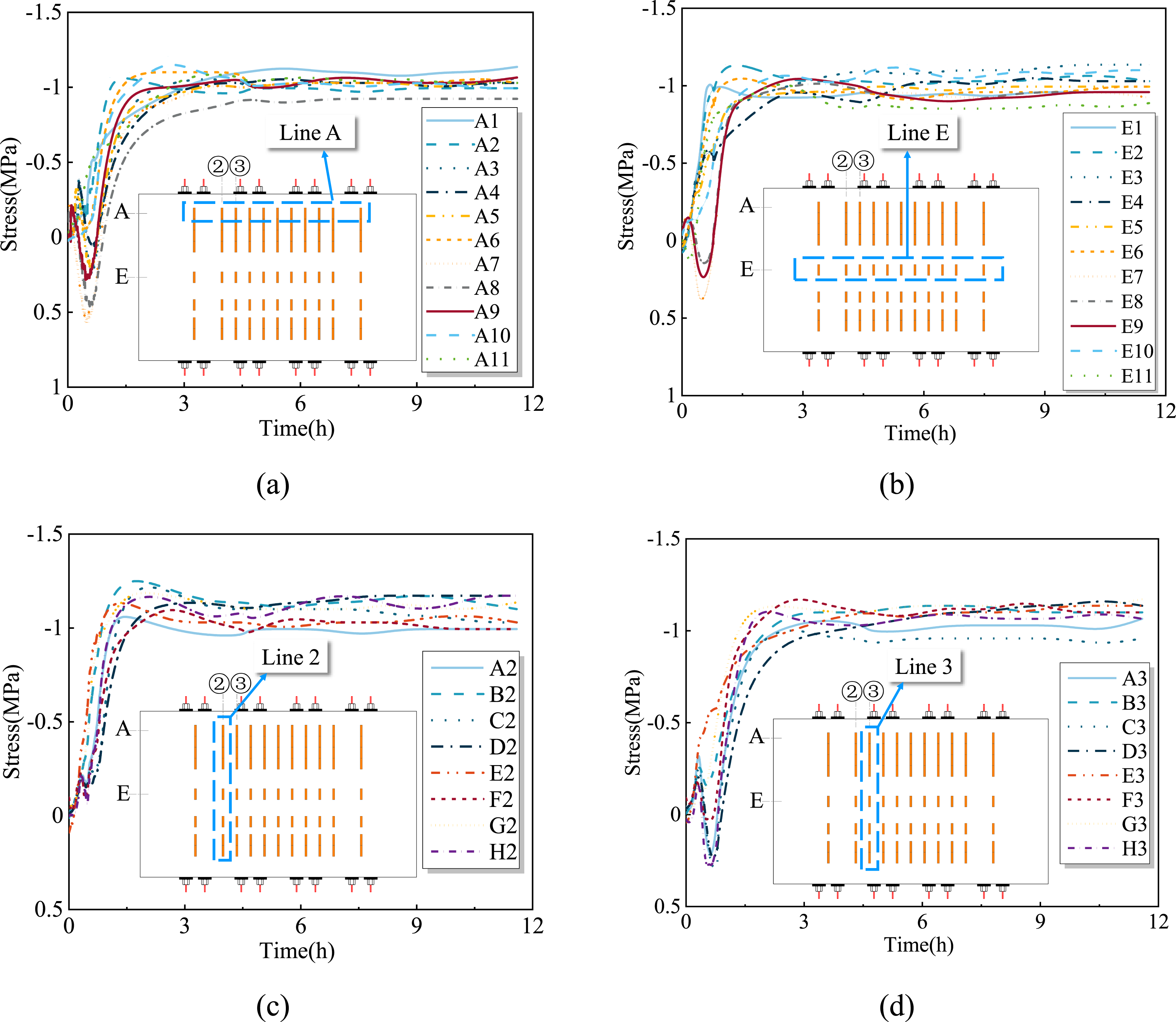
Figure 9 illustrates the progression of stress of the concrete surface following the activation of Fe-SMA rebar. During the cooling process, either line A at 0.175 m from the end of the rebar or line E at the middle position, initially experienced tensile stress resulting from thermal expansion caused by electrical activation. As the specimen cooled, compressive stress progressively took over when the Fe-SMA rebar’s pressure exceeded the concrete’s thermal expansion, resulting in a “tension-to-compression” curve progression. The most distant area from the Fe-SMA rebar (Line 2 at 0.165 m) exhibited negligible stress variations prior to the completion of activation. However, following cooling, a temporary reduction in stress was observed at D2-F2 due to residual thermal tension, which ultimately returned to a state of compression after temperature stabilization. The tension-compression sequence was validated by points C3-H3 on Line 3 (Figure 9(d)), aligning with the findings of Dong et al. (Dong et al., 2023), which confirm that the highest temperature occurred at the midspan of the rebar during activation.
The specimen’s total strain stabilized 4 h after Fe-SMA activation, with compressive stress maintained at −1 MPa (concrete elasticity modulus: 35.5 GPa (China Architecture and Building Press, 2015)). Figure 9 illustrates that the concrete compressive stress reached its maximum between 1.5 and 2 h, followed by a slight decline, ultimately stabilizing, which corresponds with the recovery stress curve of Fe-SMA in air. The peak recovery stress was observed during the cooling phase, but it diminished due to the crystal structural changes and relaxation under high-stress conditions. The stabilized −1 MPa stress after 4 h may be chosen as the stress supplement effect following Fe-SMA activation.
Figure 10 presents a comparison of stress distributions between Fe-SMA rebars (F-500/F-250) and the screw-threaded steel bars (S-0%-0). In contrast to the screw-threaded steel bar that depends on anchors, Fe-SMA achieves prestress through activation following mortar restraint. During the cooling process, the shape memory effect of Fe-SMA induced contraction, which was constrained by end nuts and mortar bonding, resulting in uniform self-prestress along the rebars (Figure 10). Stress variations were 4.402 MPa for S-0%-0 Line A compared to 0.308 MPa (6.98%) and 0.639 MPa (14.5%) for F-500/F-250, indicating the superior prestress homogeneity of Fe-SMA over conventional anchored systems. Stress curves of Fe-SMA rebar-only specimens after activation: (a) F-500; (b) F-250.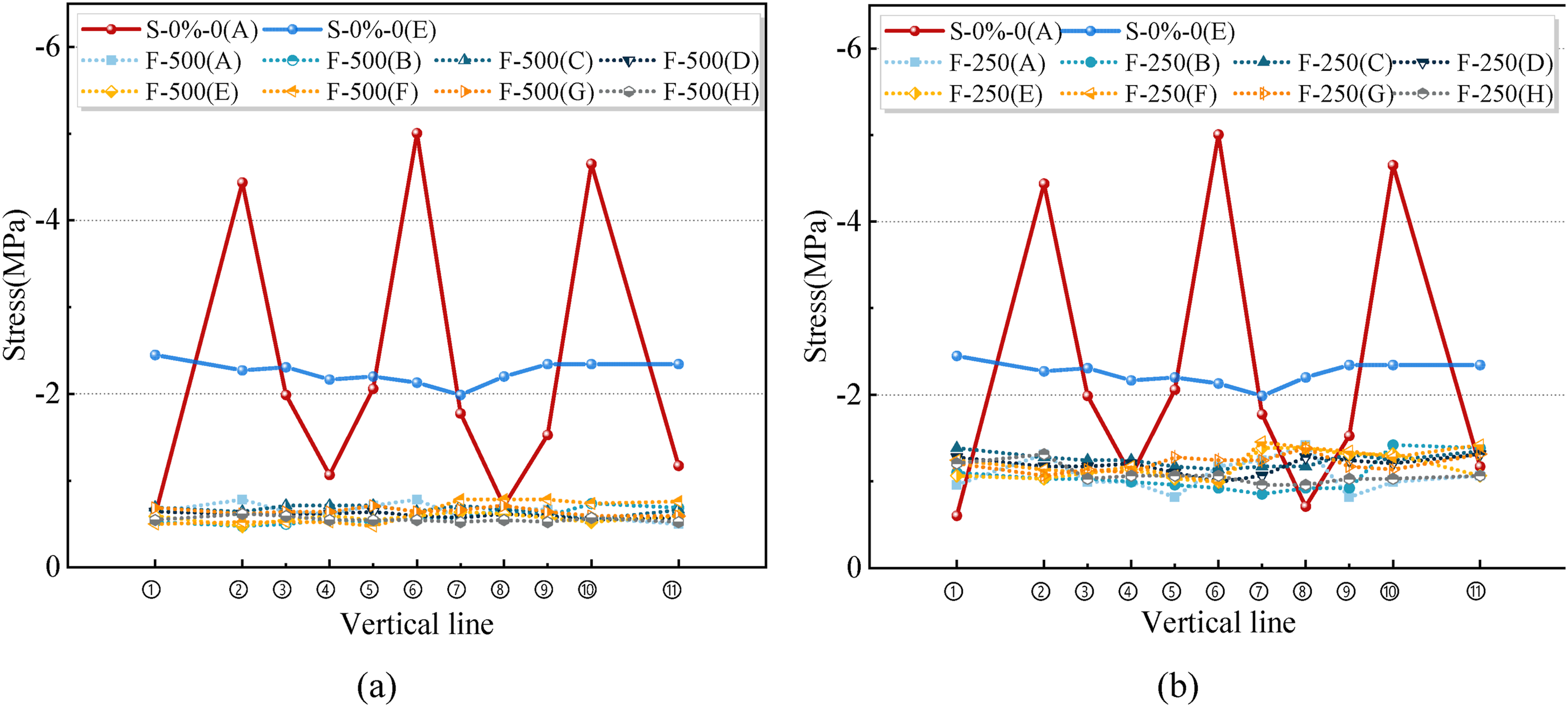
Supplementary effect of activating Fe-SMA rebar
Stress versus position curve
Figure 11 illustrates the horizontal stress distributions in specimens subjected to screw-threaded steel bar tensioning in conjunction with Fe-SMA activation (A) and those with screw-threaded steel bar tensioning only (NA). Compressive stresses generated by the screw-threaded steel bars follow a normal distribution along the prestress axis, with a peak at the center and a lateral diffusion (Figure 11(a), (b), (e), (h)). Stress uniformity diminishes toward the upper and lower edges, exhibiting the least variation at the central line E. In specimen S-0%-0, line A exhibits maximum (−5.01 MPa) and minimum (−0.60 MPa) stresses with a difference of 735%, while line H shows a 297% difference. In contrast, line E demonstrates only a 23.1% difference, ranging from −2.45 MPa to −1.99 MPa. This illustrates the non-uniform vertical stress distribution in conventional prestressed steel systems. Stress distribution in the transverse direction: (a) Line A; (b) Line B; (c) Line C; (d) Line D; (e) Line E; (f) Line F; (g) Line G; (h) Line H.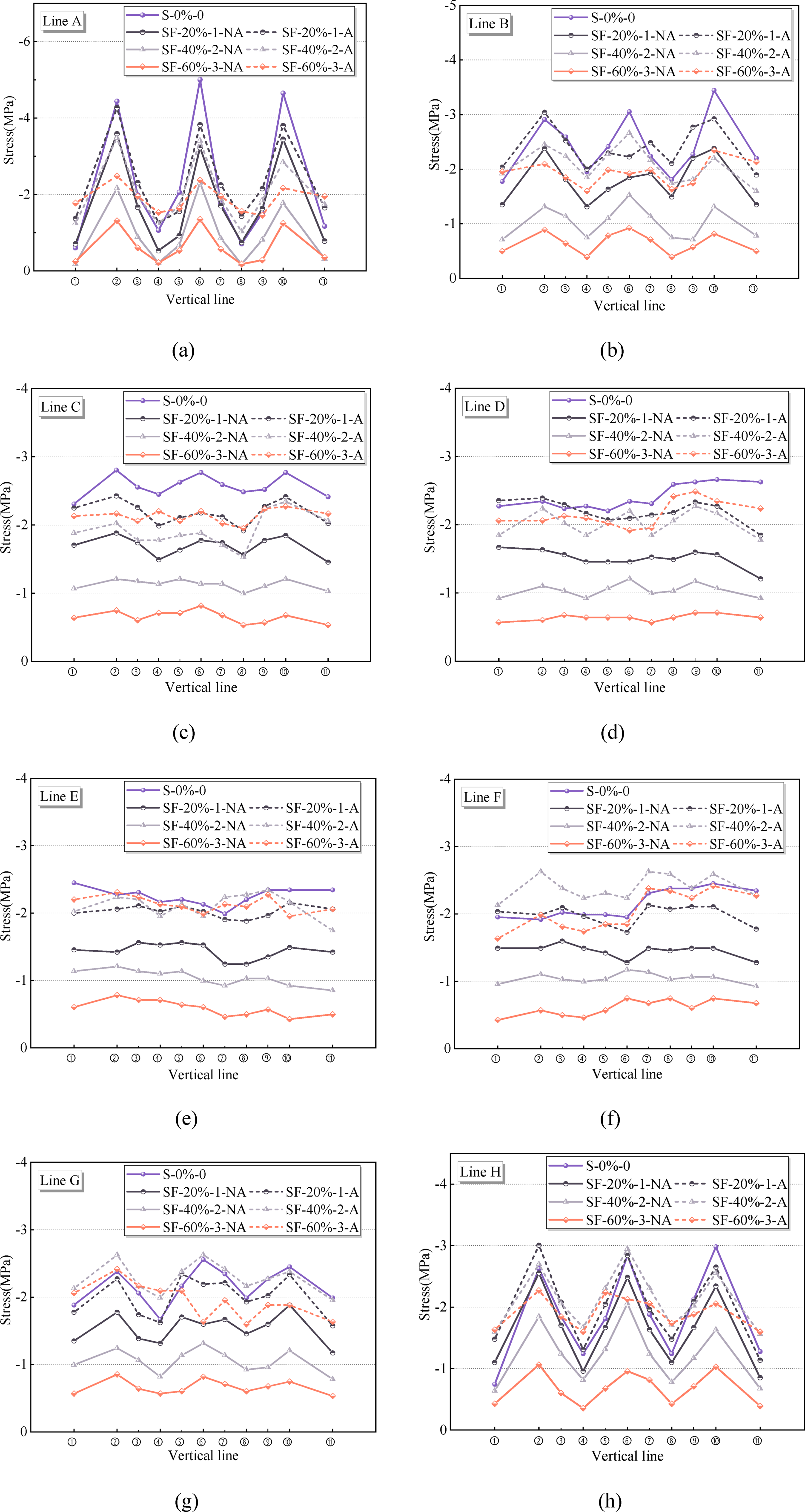
Figure 11(a) shows the comparable stresses between SF-20%-1-N and S-0%-0 at the same locations (A1, A4, A8, and A11), suggesting that the influence of vertical prestress in the mid-region diminishes with increasing height due to fan-shaped diffusion. SF-60%-3-N exhibits maximum stress of −1.35 MPa exclusively at the tension end, while other regions remain below −1 MPa (Figure 11). This illustrates that the screw-threaded steel bar tensioning has a limited impact across the plate when vertical prestress losses surpass critical thresholds.
The electric activation of Fe-SMA markedly improved the anti-cracking capacity in regions of low stress. Figure 11(a) and 11(h) illustrate a significant improvement in the compressive stress within the mid-region of screw-threaded steel bars (lines A/H near the tension and anchorage ends), effectively counteracting prestress loss. At vertical lines 2, 6, and 10, the stresses of SF-20%-1, SF-40%-2, and SF-60%-3 increased from −3.4, −2.1, and −1.3 MPa to −3.8, −3.4, and −2.3 MPa post-acti
Analysis of six lines (excluding A/H) in Figure 11 showed that the uniform stress zone increased from −0.5 to −1.5 MPa (prestress loss specimen) to over −2.1 MPa (S-0%-0), which enhanced vertical compressive stress reserves and resistance to web cracking. In contrast to traditional prestressed materials, which stabilize stress primarily near mid-sections, Fe-SMA activation produced self-prestress that uniformly enhanced plate stress when the spacing was less than 500 mm. The elevated post-activation stress curve in Figure 11 (compared to the screw-threaded steel bars tension) illustrates the significant potential of Fe-SMA as a vertical prestress supplement.
Comparison of stress values
Stress blank area
The diffusion effect below the anchor of a conventional prestressed bar causes a zone of insufficient prestress between the two prestressed reinforcement bars close to the two ends, which is referred to as the stress blank area (Yin, 2020). The stress rise in the blank area directly reflects the recovery stress transfer efficiency from the Fe-SMA to the surrounding concrete. Monitoring this region enables the quantification of local stresses, which is essential for evaluating the long-term durability of the hybrid reinforcement system. Therefore, the average stress values of prestress loss specimens SF-20%-1, SF-40%-2, and SF-60%-3 at the position of the minimum vertical stress (H1, H4, H8, and H11) on the H line before and after activation were measured and compared with those of specimen S-0%-0 to study the stress-lifting effect of Fe-SMA rebar on the stress blank area. The results are shown in Figure 12. Average stress of the specimens at the median section: (a) Line H; (b) Line E.
As the tensile force of the screw-threaded steel bar diminished, the compressive stress in the blank region correspondingly dropped, as illustrated in Figure 12. The influence of electric activation generated by Fe-SMA rebar on height at a diffusion angle of 26° was distinctly observable. The SF-20%-1, SF-40%-2, and SF-60%-3 grew at rates of 19%, 44%, and 44%, respectively, from −1.00 MPa, −0.73 MPa, and −0.40 MPa to a range of −1.35 MPa to −1.64 MPa, exceeding the value of S-0%-0 (−1.13 MPa). The specimen’s stress increased from −55% and −38.4% to −12.7% and −0.4% on line E, resulting in an enhancement of the stress value at the specimen’s midway.
In addition, the stress in the middle of the stress blank area of the two screw-threaded steel bars exceeded the stress-filling condition of the specimen without prestress loss. It can fully compensate for the stress drop caused by prestress loss, effectively increase the height of the stress blank area, and significantly enhance the anti-cracking performance of the stressed weak area of the web.
Plane stress distribution
As shown in Figure 13, Origin was used to draw the stress data of the specimen into a plane stress cloud diagram when only the screw-threaded steel bar was stretched and when it was extended and the Fe-SMA rebar was activated. Maximum stress is observed at the tension point of the screw-threaded steel bars. Specimen SF-60%-3-NA demonstrates a diminished stress distribution, with color variation around the screw-threaded steel bars being less pronounced compared to the reference specimen S-0%-0 (Figure 13(f)). The initial point of stress diffusion is below −1.4 MPa, suggesting that significant prestress loss undermines stress diffusion and poses risks associated with low stress levels. Cloud diagrams of the specimen stress plane before and after activating the Fe-SMA rebar: (a) F-500; (b) F-250; (c) S-0%-0; (d) SF-20%-1-NA; (e) SF-20%-1-A; (f) SF-40%-2-NA; (g) SF-40%-2-A; (h) SF-60%-3-NA; (i) SF-60%-3-A.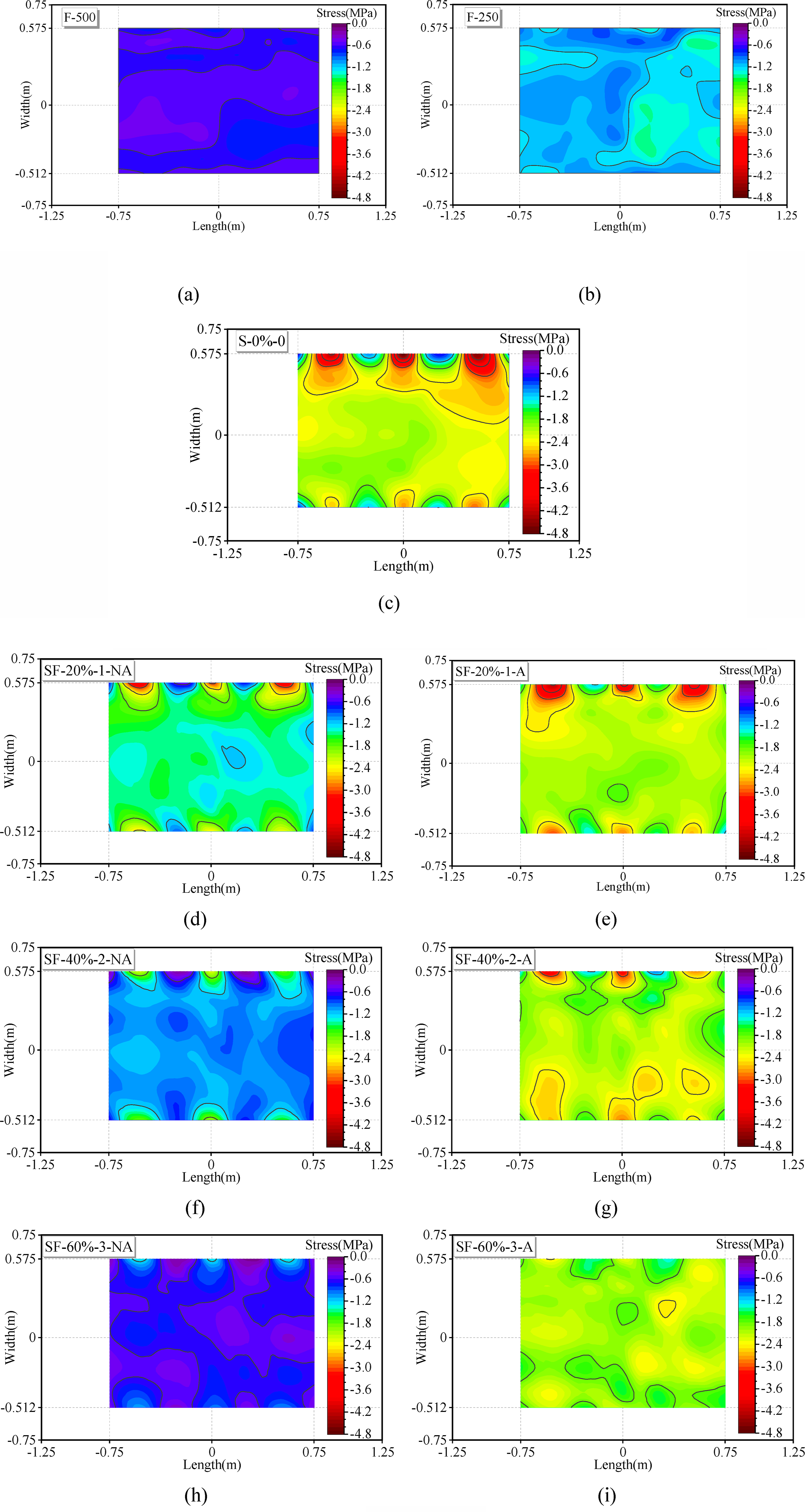
The Fe-SMA specimens F-500 and F-250 demonstrate a uniform stress distribution following activation (Figure 13(a)–(c)). Reducing rebar spacing results in an average stress increase of 87.9% (from −0.612 MPa to −1.15 MPa). Activation comparison diagrams (Figure 13(d)–(i)) illustrate the effective prestress generation of Fe-SMA. Post-activation stress approaches reference levels (S-0%-0) irrespective of initial conditions. The “stress-blind zone” between the screw-threaded steel bars transitions from low-stress blue to medium/high-stress green-red hues, demonstrating the effectiveness of Fe-SMA in improving localized stress and crack resistance under conditions of prestress loss.
Conclusions
The practicality of adding Fe-SMA rebars to box-girder webs to compensate for vertical prestress loss was examined in this study. The impacts of critical variables on the stress of the concrete plate were examined, including the type of prestressed rebar, the activation state of the Fe-SMA rebar, and the distance between the prestressed rebars. In addition, the temperature field and stress-diffusion variables of the specimens were examined. The main conclusions are as follows: (1) It only takes 30 s of electricity to raise the temperature of the Fe-SMA rebar in a concrete setting to the desired 200°C. The surface temperature of concrete barely varies by 2.9°C throughout the heating and cooling processes. The study clearly shows that using a high-current electrical power supply for resistance heating not only allows the Fe-SMA rebars to be fully activated quickly and effectively but also reduces the risk of bonding damage or cracking from the extreme temperature differential in the concrete. (2) The total strain of the specimen stabilized after approximately 4 h of Fe-SMA rebar activation. The temperature of the Fe-SMA in the concrete environment dropped to room temperature, or the entire temperature of the specimen returned to room temperature, and the recovery stress generated by the Fe-SMA rebars stabilized, demonstrating a good prestress supplementary effect. (3) The Fe-SMA rebar produced extremely consistent and effective self-prestress. The central region stress of specimens with different levels of prestress loss can be increased from approximately −0.5 MPa to −1.5 MPa to above −2.1 MPa of specimen without prestress loss by activating varying numbers of Fe-SMA rebars. This offers a more stable and elevated vertical compressive stress reserve for the box girder structure, thereby enhancing the cracking performance of the box-girder web. (4) The stress of the prestress-loss specimen can be increased to the stress-filling stage of the specimen without prestress loss when the Fe-SMA is activated. An analysis was conducted on the stress cloud diagram of the specimen before and after activation, as well as the stress-lifting effect of the center part of the two screw-threaded steel bars. After activating, the Fe-SMA rebar placed between the screw-threaded steel bars increased the stress to more than 1.5 MPa in the middle of the stress blank region of the two screw-threaded steel bars.
The primary objective of this study is to examine the capacity of Fe-SMA rebar to compensate for vertical prestress loss. Expanding upon the experimental validation detailed in this paper, the authors’ team conducted additional research into the crack resistance performance of box girder web models subjected to intricate stress fields, encompassing the combined influences of conventional vertical prestress, Fe-SMA self-prestress, longitudinal prestress, and external loads. The findings of this comprehensive investigation, including the interaction of different stress factors, will be presented in a future paper. The main challenge faced by the future application of box girder flanges is to determine the optimal Fe-SMA rebar substitution rate. As a potential supplementary prestress material, the corresponding relationship between the self-prestress value, reinforcement ratio and vertical prestress loss of Fe-SMA rebar needs to be explored, as well as the variation law of the main tensile stress of the web section after the self-prestress supplementation.
Footnotes

CRediT authorship contribution statement
Zhiqiang Dong: Conceptualization, Supervision, Formal analysis, Writing – review & editing, Funding acquisition. Longlong Hu: Conceptualization, Investigation, Methodology, Writing – original draft, Visualization. Ziqing Liu: Writing - review & Editing, Methodology, Formal analysis. Xinliang Sun: Data curation, Writing - original draft. Hong Zhu: Writing - review & Editing, Conceptualization, Funding acquisition, Supervision. Yijie Pan: Conceptualization, Supervision.
Funding
The authors disclosed receipt of the following financial support for the research, authorship, and/or publication of this article: The authors would like to acknowledge financial support from the Excellent Youth Foundation of Jiangsu Province of China (No. BK20230088), the National Natural Science Foundation of China (No. 52378139), the National Natural Science Foundation of China (No. 52478307), the Fundamental Research Funds for the Central Universities (No. 2242022k30031).
Declaration of conflicting interests
The authors declared no potential conflicts of interest with respect to the research, authorship, and/or publication
Data Availability Statement
All data that support the findings of this study are included within the article (and any supplementary files).