
Abstract
A rectangular jet emerging from a nozzle with embedded swirl vanes in its exit boundary layer is studied. The swirling shear layer imposes an external torque on the jet boundary where it causes jet rotation in the direction of axis switching, skew deformation as well as enhanced mixing. In moderate aspect ratio rectangular nozzles, e.g. AR = 5:1, a pair of co-rotating streamwise vortices is formed on the narrow boundary of the jet that dominates its dynamics in the near field. A vortex-induced model is developed that accounts for the rotation of the rectangular jet with embedded shear layer swirl. The model also shows that the jet rotation is diminished with increasing aspect ratio, as AR−2. The higher entrainment rate in the rotating jet with skew deformation causes the jet mass flow rate with shear layer swirl to be 20–25% higher than the corresponding plain rectangular nozzle of the same aspect ratio (x/De > 1). The proposed model is validated using computational simulation results of previous investigations that appeared in the literature.
Introduction
Turbulent-free jets, with and without swirl and excitation, have been the subject of extensive studies at NASA under the leadership and collaboration with Rice.1–8 Vortex roll up in the emerging shear layer and the subsequent large-scale structures coupled with forced excitations, i.e. instability waves, to create mixing enhancement in turbulent free jets. Asymmetric jets, e.g. emerging from elliptic or rectangular nozzles, created new dynamics known as axis switching. Hussain and Husain 9 and Zaman 10 among other researchers have experimentally studied this phenomenon. The induced dynamics of azimuthal vorticity, ωθ in asymmetrical jets is the dominant mechanism responsible for the phenomenon of axis switching. However, streamwise vorticity, ωx-induced dynamics, also contributes to the evolution of an asymmetric jet, as noted by Zaman 10 and Samimy et al. 11 These two dynamics are coupled and compete with each other, which may hinder or promote switchover of asymmetric jets. The study of coupled interaction of ωθ–ωx using delta tabs, as a means of generating streamwise vorticity, is experimentally conducted.11–14 Zaman et al. 15 recently wrote an excellent review of this topic. The role of swirl in free turbulent jets is to trigger centrifugal instability, set up radial pressure gradient and thus promote mixing.8,16 However, swirl in aircraft exhaust systems creates a penalty on thrust production, 17 which limits its deployment to very selective applications, e.g. in combustion chambers. It is important to reiterate that the phenomenon of “axis switching” driven by ωθ and ωx dynamics in elliptical or rectangular jets do not involve physical rotation of the jet, rather the shrinkage in one dimension and the elongation in another that may repeat in the streamwise direction. However, when a jet is subjected to external torque through induced swirl in its shear layer, as in the present study, the phenomenon of “axis switching” involves the physical jet rotation. In this sense, it is a new dynamics in turbulent jets that create “axis switching”.
To minimize the thrust penalty of large-scale (bulk) swirling jets, the case of embedded swirl in the nozzle exit boundary layer is investigated.18,19 The solution offers the benefits of swirl in mixing enhancement without a major penalty of thrust loss. The external torque in our configuration, as an initial boundary condition, dominates the mechanism of jet rotation, whereas the switchover phenomenon in asymmetric jets is caused by ωθ-dynamics. We proceed to model the former mechanism.
Rectangular jet with swirling shear layer
A 5:1 aspect ratio rectangular nozzle has short and long (inner) dimensions of 6 and 30 mm, respectively. The equivalent round diameter of the jet is De = 15.1 mm. The nozzle exit has incorporated counterclockwise vanes, with vane angle of θ0 = 30° with respect to the nozzle’s axial direction. The vanes are carried over to the sides of the nozzle as well. The height of the exit swirl vanes is 1 mm. The initial swirl distribution in the shear layer is assumed to be Vxtan θ0, where Vx is the initial axial velocity.
The nozzle is of convergent type and is under-expanded with choked exit. The jet Mach number, corresponding to perfect expansion, is 1.53.
The temperature at the nozzle exit is 250 K and the fluid density is 1.414 kg/m3. Additional description for initial condition, boundary conditions and CFD parameters is detailed in Han et al.18,19
Schematic drawing of the rectangular nozzle with its exit flow condition is shown in Figure 1(a). Figure 1(b) shows the counterclockwise vane placement and its geometry in the nozzle exit. The flow in the y–z plane shows that the boundary layer swirl is confined to a narrow strip around the periphery and is in counter-clockwise direction. Figure 2 shows the formation of two corner vortices on the short dimensions of the nozzle that are co-rotating and are in streamwise direction. The diameter of these corner vortices in moderate to high aspect ratio nozzles, say >5:1, scales as h.
(a) Definition sketch of the rectangular nozzle exit geometry with embedded boundary layer swirl and coordinate system. (b) Details of the counterclockwise swirl vanes and their dimensions in the nozzle exit (from Han et al.
19
). Corner flowfield modeled as a pair of co-rotating vortex filaments in high-aspect ratio rectangular nozzle.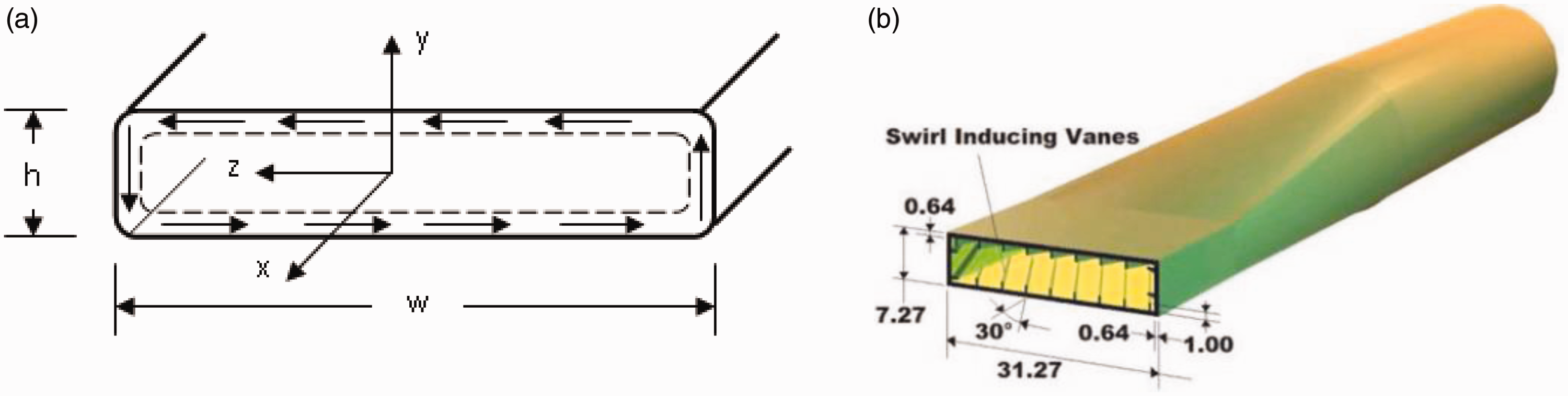

The dynamics of the jet in near field
The external torque that was applied to the rectangular jet at the nozzle exit manifests itself in angular momentum distribution along the broad and short dimensions of the jet. The geometrically imposed boundary condition on the narrow side creates a pair of streamwise vortices that scale as h and with centerline distance of w-h, as shown in Figure 3. These vortices act as a pair and rotate in the counterclockwise direction, thus controlling the dynamics of jet rotation in the near field.
Circular trajectory of a pair of co-rotating vortices in the corner regions of the rectangular jet.
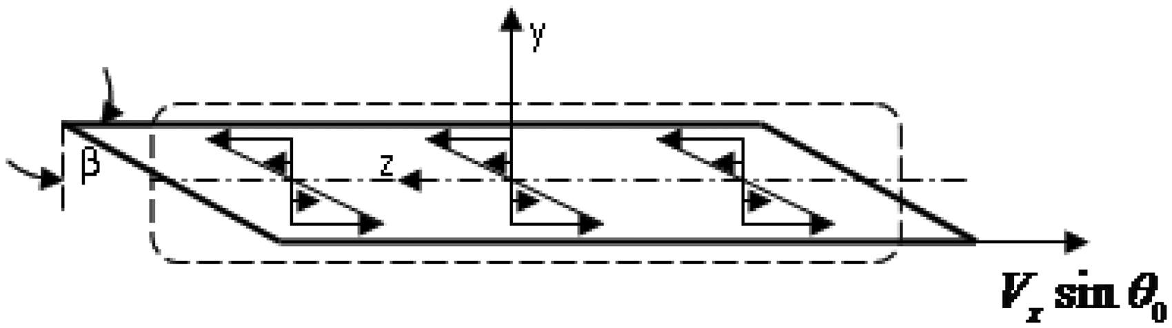
The angular momentum distribution on the broad side of the jet has a small moment arm from the z-axis, as shown in Figure 4. A representative distribution of the shear in the cross plane, y–z, is depicted in Figure 4, that shows a plane of symmetry. The role of the broad side shear distribution on the near field jet dynamics is to cause a skew in the rectangular jet, as depicted in Figure 5.
The vortex sheet model along the broad sides of the rectangular jet shear layer with embedded swirl. The rectangular jet skew deformation caused by the broad side shear due to embedded swirl.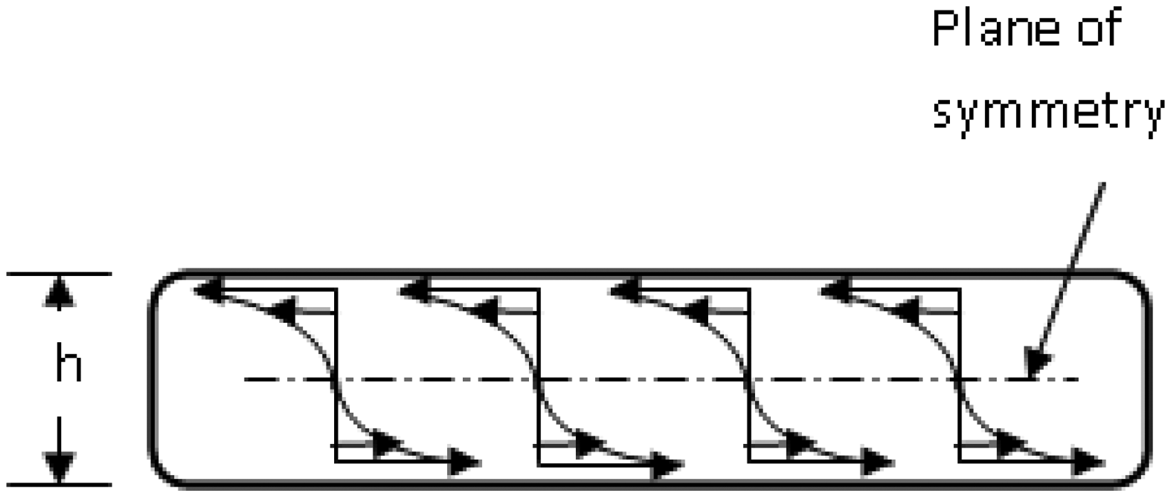
Jet rotation model
The initial swirl induced in the nozzle exit boundary layer is

The corner vortex circulation is

The self-induced rotational speed of the jet is

The ratio of rotational-to-axial speed is thus

The nozzle aspect ratio, AR, is defined as

Thus, the ratio of rotational-to-axial speed in the jet, in terms of the nozzle aspect ratio, is

The period of rotation is approximately

Axis switching phenomenon, in the context of the present problem, corresponds to T/4, therefore

The streamwise position along the jet axis where axis-switching takes place is

Dividing equation (8a) by the small dimension of the nozzle, and replacing w/h by aspect ratio, we get the non-dimensional distance along the jet where axis switching takes place, namely

Since equation (8b) shows that the location of switchover, by initial torque alone, scales as AR2, the effect of jet rotation is diminished with AR−2. We can also write equation (8b) in terms of rotation angle, θ, as

The jet skew deformation
To estimate the initial phases of the jet skew deformation corresponding to the near field, we approximate the shear stress on the broad side of the jet. Shear stress τyz is proportional to azimuthal velocity gradient and in a rectangular nozzle it exhibits a plane of symmetry. The first-order approximation of the shear is based on the linear velocity distribution between the upper and lower shear layers on the broad side. Therefore

The rate of strain deformation in y–z plane, ɛyz, for a Newtonian fluid is therefore approximated by

The conclusion from this simple model on the rate of deformation, or skew, in y–z plane, i.e. the jet cross sectional plane, is that shear deformation is proportional to the sine of the initial swirl angle, θ0, and inversely proportional to the narrow dimension of the jet, h. In the vanishing limit of the narrow dimension of the jet, the jet skew deformation becomes large and dominant. Therefore, a high aspect ratio “slit” nozzle, as found in low-observable military aircraft, with boundary layer swirl can be modeled as a thin vortex sheet where the jet dynamics is purely driven by the self-induced vortex sheet rollup, as outlined in Batchelor. 20
Model validation
To study the characteristics of supersonic rectangular jets, a computational code known as the three-dimensional Proteus code21–23 was used with a shock-adaptive grid generator developed by Han et al.18,19 The turbulence models used in the calculations were Baldwin-Lomax and Chien k-ɛ turbulence models. Chien k–ɛ turbulence model was applied to the computation after the results were obtained by using Baldwin–Lomax turbulence model in the first iteration. Han et al.18,19 describe in detail the computational simulation approach from grid generation, shock-adaptive scheme, convergence rate and numerical stability considerations. For the sake of brevity, these will not be reproduced here.
Figure 6 shows a side-by-side comparison of the axial velocity contours in the cross plane at three axial locations of a rectangular jet with embedded shear layer swirl (on the left) and one without swirl (on the right). The jet subjected to initial torque rotates in the direction of switchover in addition to undergoing skew deformation. The jet rotation based on the proposed model, i.e. equation (8(c)), at x/h = 7.5 predicts 10.7° and the rotation at x/h = 11.5 is predicted to be 16.4°. These rotation angles are drawn as straight lines (to scale) in Figure 6(c) and (e) for the corresponding axial positions. For the purpose of model validation, these lines reasonably represent the jet rotation in the near field. In terms of jet equivalent diameter, De, the two axial positions are at 3.0 and 4.6, respectively.
Axial velocity contour plots at x/h = 0, 7.5 and 11.5 downstream of a rectangular nozzle with and without boundary layer swirl (the dashed lines in parts (c) and (e) correspond to the jet rotation model, equation 8(c)).
The effect of embedded swirl on jet entrainment and thus mass flow rate is shown in Figure 7. The computational results indicate between 20 and 25% mass flow rate increase in the jet with shear layer swirl (at x/De = 1.0 and x/De = 5.0, respectively) over its swirl-free counterpart.
Comparison of mass flow rates for the plane rectangular nozzle with and without boundary layer swirl in the near field (the arrows correspond to X/De = 1.0 and 5.0) (data extracted from Han et al.
18
).
Summary and conclusions
A turbulent rectangular jet subject to initial shear layer swirl is studied. A near-field model, based on vorticity distribution, is developed that predicts the jet rotation and skew deformation, which identifies a new axis-switching phenomenon in non-axisymmetric jets. The physical jet rotation model in the x-direction, i.e. along the jet axis, is compared to 3-D computational (RANS) simulation, which seems to be in substantial agreement. The model suggests diminished jet rotation with increasing aspect ratio in proportion to AR−2. The embedded swirl in the nozzle boundary layer adversely impacts thrust production, but the enhanced entrainment (20–25%) and thus jet spread proves useful in the design of advanced low-observable aircraft.
Footnotes
Acknowledgement
The authors are indebted to Edward J Rice for his guidance, unwavering support and friendship. We learned about our own research through discussions with Ed Rice, Khairul Zaman, Ganesh Raman, Reda Mankbadi, J Panda among many others who made CW-17 the most productive Lab at NASA-LeRC. The efforts of Mr Ralph Fallert, who provided technical support to the research team for many years with modifications, nozzle installations, and component fabrications in CW-17 and other research facilities at NASA LeRC are also greatly appreciated. We are indebted to all of our graduate students, but in particular, to our doctoral students, Gary Cheng, Charlie Wu, Ron Barrett, Kyle Wetzel, Wonjoong Lee, Sueng-Jae Hwang, SY Han, Wonjin Jin, Leslie Smith, Sonja Flesberg, Alex Karwas, and Amool Raina, who have been our partners in research.
Declaration of conflicting interests
The author(s) declared no potential conflicts of interest with respect to the research, authorship, and/or publication of this article.
Funding
The author(s) received no financial support for the research, authorship, and/or publication of this article.