



Abstract
Jet flows impinge on launch pad structures and aircraft carrier deck blast deflectors. Turbulent structures are deformed and acoustic radiation is reflected by the deflector. The coupling of reflected acoustic waves with the instability waves of the jet turbulence increases their amplitude and causes a feedback loop. Resultant far-field acoustic radiation is amplified. This amplification results in additional tones with significant spectral broadening occurring at frequencies corresponding to the constructive interference. We present a simple prediction methodology in the form of an acoustic analogy. The analogy accounts for reflected acoustic waves through a tailored Green’s function and models the large-scale structures as spatially and temporarily growing and decaying instability waves. The predictions are compared with two experimental datasets. Predictions compare favorably with measured frequencies and spectral broadening in the far-field.
Introduction
High-speed off-design jet flows from military engines and rockets continue to cause harmful noise radiation. Additional noise sources form when jet flows impinge on blast deflectors. For example, acoustic loading on the propulsion system is quantified by Eldred 1 and noise on aircraft carriers is quantified by Aubert and McKinley. 2 Radiation reflected or created by the blast deflector alters the turbulent structure within the jet. At particular frequencies, the large-scale turbulence within the jet is amplified and coupled with the feedback from the impingement surface. This feedback process causes the far-field radiated noise from large-scale structures to be amplified. In this paper, we propose a simple model to predict the spectral broadening and amplification of the radiated noise from large-scale coherent turbulence in the presence of structures.
Noise radiation from jet flows is complex and contains many sources that include mixing and shock-associated noise. The shock-associated noise is both tonal and broadband in nature, where the broadband component is often called broadband shock-associated noise (BBSAN). Mixing noise is divided into contributions from the relatively spatially incoherent turbulence that is locally isotropic, the large-scale turbulent structures that are highly spatially coherent and anisotropic, and the Mach wave radiation. In this paper, a jet operating in an environment without interference of its development is a “free-jet”. Additional noise sources occur when disturbances or solid structures are present. For example, when a jet interacts with a plate that is aligned with the flow (a ground surface) or impinges on a surface (a deflector), then additional sources are created, which are called jet structure interaction noise (JSIN), and the free-jet sources are altered.
Figures 1 and 2 show an isometric and side view of the jet impingement problem analyzed in this paper. In Figure 1, the observer and source vectors are defined as X and Y, respectively. The location of the trailing edge of the deflector is defined by xp and yp. Figure 2 shows the inclination angle α of the impinging plate, which is the angle of the deflector relative to the jet axis. Figure 2 illustrates large-scale structures of the jet as well as the acoustic waves scattered by the deflector edge. Instability waves generated from the nozzle will propagate downstream, deflect from the plate, and propagate back upstream and interact with the jet.

Isometric view of the problem setup.

Side view of the problem setup with large-scale structures and acoustic waves.
The measured spectra from an off-design jet is shown in Figure 3, where both the free-jet of the small-hot jet acoustic rig (SHJAR)
3
and installed jet of the jet structure interaction test (JSIT)
4
are shown as lines with symbols. The JSIT contained a large flat plate near the jet flow. Predictions and measurements of the free and installed jet correspond to the SHJAR Small Metal Chevron 16 (SMC016) nozzle operating at

Predictions and measurement of the free-jet and installed jet corresponding to the SMC016 nozzle operating at
When jets operate in the vicinity of structures, the incident acoustic waves may reflect back into the flow-field. These acoustic waves alter the aerodynamic noise sources and a coupling feedback loop is created. This feedback mechanism was documented using ultra-high frame rate schlieren in an impinging underexpanded supersonic jet by Mitchell et al.
8
Figure 4 shows one frame of the schlieren of Mitchell et al.,
8
where the off-design jet flows from top to bottom. The jet impinges on a blast deflector that is normal to the flow (

Schlieren of a jet impinging on a blast deflector. Flow is from top to bottom and an impingement plate is at the bottom. An acoustic wave is traveling upstream and alters the instability wave. Used with permission of Mitchell et al. 8

A schlieren of a jet moving left to right where a large instability wave is circled. Used by permission of Mitchell et al. 8
Experimental research
Several experimental investigations on jet impingement have demonstrated the effects of a feedback loop generated by acoustic waves interacting with instability waves. Powell
9
was likely the first to examine the interaction of acoustic waves within a supersonic off-design jet flow. Powell
9
placed a reflector near the flow and also introduced an edge in the flow to examine this effect. Glass
10
created shadowgraphs of the jet when there was a reflecting surface, with and without fiberglass, near the nozzle. The results showed that the jet decayed more rapidly when the reflecting surface was exposed and, subsequently, a dominant tone was present in the cases of more rapid jet decay. This lead to the notion of an acoustic feedback mechanism disrupting the flow. Weightman et al.
11
employed ultra-high-speed schlieren images to analyze a periodic transient shock in the wall jet region of an underexpanded jet impingement. Weightman et al.
11
argued the phase lag between the shock formation and acoustic wave formation causes a phase lag in the acoustic feedback process. Henderson et al.
12
investigated the structure of a supersonic jet impinging on a flat plate at various Mj and
A similar experiment of Akamine et al.
13
examined acoustic waves generated from the impingement region of the jet with a flat plate at a 45º. They determined that two types of acoustic waves were generated in this impingement region, with propagation directions of 30º and 75º from the plane of the plate. Ito et al.
14
classified a particular jet impingement flow as “Type 1 with Bubble”, which occurs when the plate angle is greater than 50º and
Computational and theoretical research
Several studies involving large eddy simulation (LES) and detached eddy simulation (DES) have been performed to study the structure and acoustic feedback mechanism in impinging jets. Brown and Frendi 17 used DES to study the near-field acoustic spectra of a converging-diverging nozzle exhausting on a flat plate and showed that smaller plate to nozzle distances resulted in increased near-field SPL. Gojon et al. 18 and Gojon and Bogey 19 investigated acoustic properties of planar and round jets impinging on a flat plate. In both cases, near-field pressure data was sampled and Fourier decomposition was performed to extract the amplitude and phase of dominant tones. Uzun et al. 20 used LES to investigate tonal production from jet impingement on a flat plate during isothermal and heated conditions. They performed dynamic mode decomposition and showed that the most dominant mode of the flow-field had a temporal frequency related to the impingement tone frequency. The results of Uzun et al. 20 show the relationship between the acoustic feedback mechanism and tonal noise produced by the jet. Golubev et al. 21 used an LES with a wall-model to capture the acoustic feedback mechanism to study the variation of α and the directivity of the acoustic field.
A number of other computational investigations have been performed without the use of LES and DES. Goto et al. 22 performed Reynolds-averaged Navier–Stokes (RANS) simulations to investigate the shock structure of jets impinging on a plate at different angles. Using an implicit LES alongside the RANS simulation, they found that treble points from the jet shock, plate shock, and tail shock move intensely along the plate. Honda et al., 23 using a modified weighted nonlinear scheme, observed acoustic waves emerging from two different sources near the plate. These two sources are the interaction of the plate shock and shear layer and the interaction of the bubble shock and shear layer. For a more comprehensive review of numerical studies of the jet impingement flow-field.24–26
Several other computational investigations have taken different approaches to analyzing the jet impingement problem. Hong and Jeon 27 and Tsutsumi et al. 28 implemented a Roe flux splitting scheme and a hybrid LES/RANS scheme, respectively, to resolve the impingement flow-field. McIlroy and Fujii 29 approached the jet impingement problem using a simple high-resolution upwind scheme for the convective terms. This method enabled McIlroy and Fujii 29 to capture the structure of the flow such as shocks and pressure peaks on the plate.
A number of theoretical studies examined jet impingement and the acoustic feedback phenomena. Messersmith 30 employed a convection-entrainment model, similar to the one developed by Nosseir and Ho, 31 to predict the impingement tones produced by jet impingement. The model provides a simple means of predicting impingement tones and requires only the nozzle pressure ratio (NPR), TTR, and xp. Papamoschou 32 and Papamoschou et al. 33 constructed a wavepacket model and calibrated it with far-field acoustic measurements. The model used steady RANS simulations and a scattering technique to predict installed jet noise. Cavalieri et al. 34 computed a scattered sound field around a semi-infinite flat plate using a tailored Green’s function and compared the results to experimental data. They showed that the plate-jet interaction causes an amplification of low frequency noise, which alters the far-field measurements at low frequencies. Huber et al. 35 investigated the flight effect on noise scattered by the trailing edge of a flat plate. They modeled the flat plate using a tailored Green’s function, assuming the plate was semi-infinite, and a boundary element method formulation of the Helmholtz equation. Both the tailored Green’s function approach and the boundary element solution agreed with measurement. This comparison provides evidence that for a sufficiently large plate a tailored Green’s function can be used in place of a boundary element method formulation.
Present approach
In this paper, we predict the interference pattern of the radiated acoustic waves from the large-scale turbulence or instability waves within an off-design supersonic jet. The scattered waves (due to impingement) interact with the model of the instability wave basis function and amplify or destruct it through the effect of interference. The scattered portion of the problem is governed by the tailored Green’s function of a semi-infinite flat plate. The source depends on the scattered acoustic field, which results in a model equation that is not truly closed form. For this reason, we evaluate the equation recursively to obtain an amplified instability wave, and then predict the far-field acoustic pressure. The far-field acoustic pressure, due to the amplified instability wave basis function, is compared with measurement. The initial model is calibrated with jets operating without impingement.
The next section of this paper presents the mathematical model for the prediction of the interference pattern of radiated acoustic pressure spectra. Next, the results are presented for the tailored Green’s function, the basis function of the instability wave, static jets without impingement, and the interference pattern due to jet impingement. Finally, a summary of the findings are presented.
Mathematical model
The governing equations are the Navier–Stokes equations. We initially follow Lighthill
36
and define the continuity equation as







We must now find the free-space Green’s function and tailored Green’s function. It is well known that the solution of equation (6) in three-dimensional space is

A tailored Green’s function, gt, is required for the solution in the presence of an impingement plate. We adopt the approach of Ffowcs-Williams and Hall,
37
where Lighthill’s equation is written as the inhomogeneous Helmholtz equation. The acoustic velocity normal to the semi-infinite plane is zero. Ffowcs-Williams and Hall
37
apply Gauss’ theorem to convert the volume integrals into surface integrals. These surface integrals vanish because of the velocity normal boundary condition. They showed that the tailored Green’s function of the Helmholtz equation in the far-field for the semi-infinite plate is described by equation (9(in the frequency domain. The inverse Fourier transform of gt will then be taken to obtain a time dependent function that is integrated in equation (22)



Here, R and R′ are the distances between the observer and the source, as well as the observer and image source, respectively. The image source is defined as the mirror image of the source across the plane of the impingement plate. The coordinate system (r, β, z) originates on the trailing edge of the plate with the z-axis parallel to the edge and β = 0 on the flat plate. We can define the values for r, β and z for some observer or source



The variable κ is the wavenumber defined as

We evaluate the integrals of equation (9) through the complex exponential in the integrand with use of Euler’s equation in equation (16) and obtain

We substitute

and

We now model the source term within equation (7), which is the double divergence of the Lighthill stress tensor. Recall that the Lighthill stress tensor is



We drop the higher order term within equation (19). The total or actual instability wave is a summation over all possible modes and wavenumbers. We adopt our models of equations (19) and (20) and substitute them into equation (7). The resultant prediction equation is
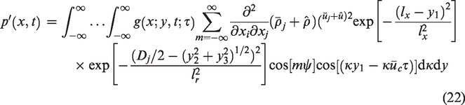
We now seek the pressure field from equation (22) in the far-field without any impingement plate nearby. Integrations of the double divergence of


Evaluation of the model equation
We now discuss the numerical evaluation of equation (22). Equation (22) is initially evaluated with a given plate impingement angle α, where α is zero for a ground surface and
Results
Scattering
The tailored Green’s function of Ffowcs-Williams and Hall 37 governs the scattering of sound about a semi-infinite flat plate and was presented in equation (18). Here, we validate gt to demonstrate that its implementation is correct and to assess error relative to another prediction approach and measurement.
We first examine the case where the source point within equation (18) lies upon the boundary condition where the normal velocity is zero. In this scenario, the resultant incident field will be equal to that of the free-space Green’s function (see Ffowcs-Williams and Hall 37 for details). Figures 6 and 7 show a contour plot of a source in a free-field and a source placed on the semi-infinite flat plate, respectively. Both contour plots have a radiating acoustic field with equal source magnitude. The tailored Green’s function (Figure 7) reduces to the free-space Green’s function correctly in our numerical implementation.

Contour plot of the magnitude of the free-field Green’s function with a single source at origin.

Contour plot of the magnitude of the tailored Green’s function with a single source placed on the semi-infinite plate.
Dunn and Tinetti 41 developed the fast scattering code (FSC) and compared their numerical predictions to an experiment (NASA TP 1004) conducted by Ahtye and Mcculley, 41 which measured the ΔdB reduction due to a source of unit strength shielded by the presence of a plate with square edges. Figure 8 shows the experimental setup of Ahtye and Mcculley. 42 In the experiment, the plate was placed 0.25 m from a monopole source of unit strength. Measurements of SPL were obtained on a linear microphone array that was five meters parallel to the surface of the plate on the shielded side. SPL was also measured along the microphone array from the same unit source without the presence of the plate to serve as a baseline. We refer to the ΔdB difference between free-field and shielded predictions or measurements as the “shielded SPL”. In order to analyze the problem of a finite plate shielding a point source, four semi-infinite flat plates are considered, with each edge corresponding to an edge of the finite plate. The four solutions for scattering around each edge are then summed together to obtain the solution for a finite plate. Note that the tailored Green’s function proposed by Ffowcs-Williams and Hall 37 does not incorporate thickness or the type of edge of the plate.

Diagram of NASA TP 1004 experiment and fast scattering code computational analysis.
Figures 9 to 12 show a comparison of shielding SPL predictions and measurements for different frequencies plotted against θ, which is defined Figure 8. The tailored Green’s function captures the mean shielding SPL compared to the experimental results when θ is less than 35º. When θ is larger than 35º, the tailored Green’s function prediction loses accuracy as it slightly over predicts SPL relative to the experimental results. Diffraction patterns are not predicted by gt because they are essentially canceled out through interference in the semi-infinite plate solution. Diffraction patterns are however observed in measurement and the predictions of FSC. Figures 9to 12 also show that as the frequency increases so does the absolute shielding SPL. Both the evaluation of gt and the FSC code are able to capture the trend of increasing shielding SPL observed in experiment. The ability of gt to capture the mean shielding SPL and the trend of increasing shielding SPL with frequency supports the method for use in our scattered jet noise predictions.

Comparison of plate shielding results with fast scattering code 41 and NASA Experiment TP 100443 for f = 1000 Hz.
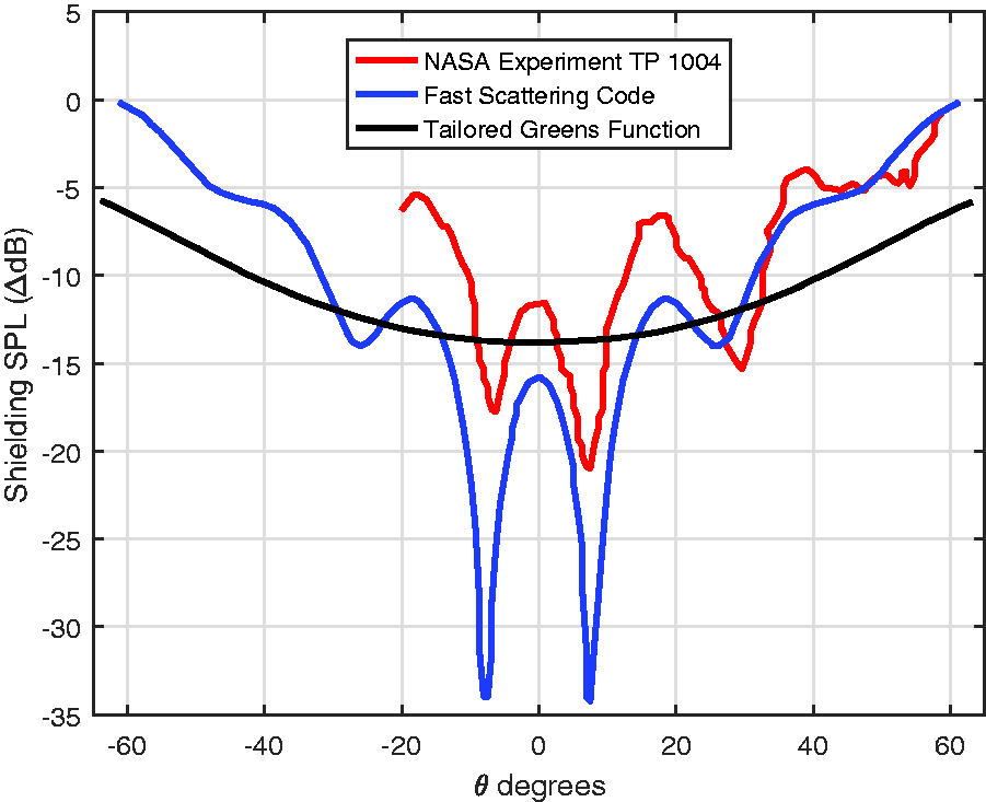
Comparison of plate shielding results with fast scattering code 41 and NASA Experiment TP 100443 for f = 2000 Hz.
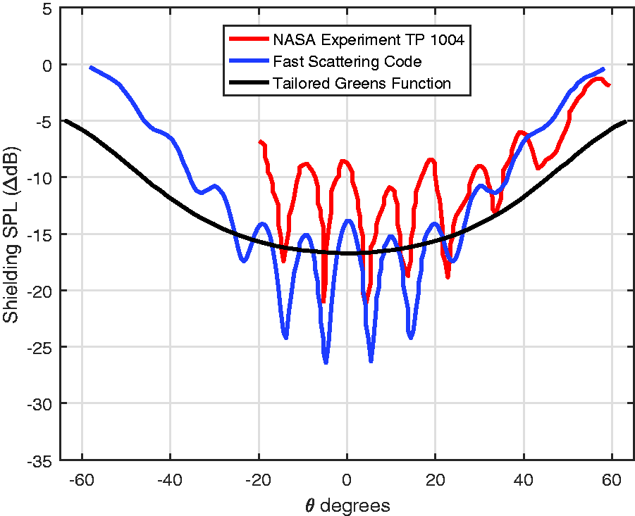
Comparison of plate shielding results with fast scattering code 41 and NASA Experiment TP 100443 for f = 4000 Hz.
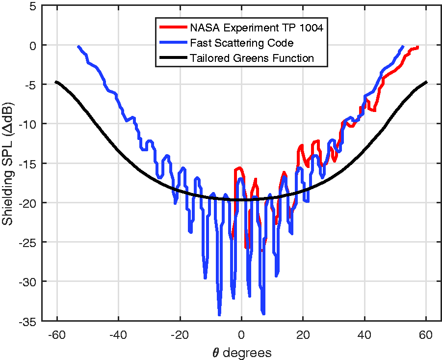
Comparison of plate shielding results with fast scattering code 41 and NASA Experiment TP 100443 for f = 8000 Hz.
Wave model
A central point of this research is the use of a basis function of the instability wave shown in equation (20) for
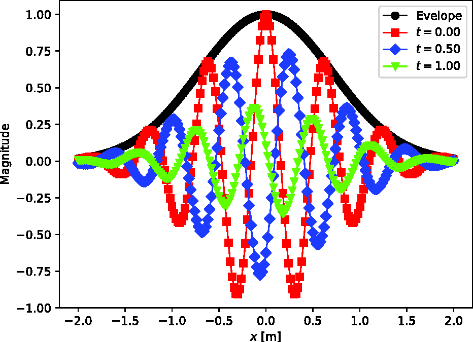
Normalized large-scale structure function centered at x = 0 at various times t constrained by an envelope.
We now examine the normalized instability wave basis function presented in equation (20). For demonstration purposes, we set D = 1 m,
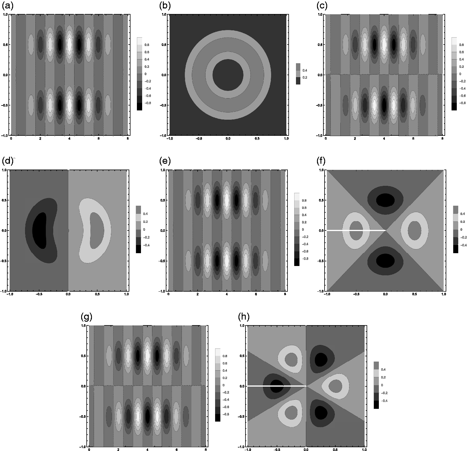
Contours of the normalized equivalent wave for modes 0 through 3 in the x–y and x–z planes: (a) m = 0 in x–y plane; (b) m = 0 in y–z plane; (c) m = 1 in x–y plane; (d) m = 1 in y–z plane; (e) m = 2 in x–y plane; (f) m = 2 in y–z plane; (g) m = 3 in x–y plane; (h) m = 3 in y–z plane.
Free-field jet aeroacoustic predictions
We now turn our attention to acoustic predictions. For the acoustic predictions, the jet operating conditions are used to estimate the jet velocity and density using the empirical models in equations (23) and (24). We examine the far-field prediction of the model against a static jet without any reflections and multiple predictions of jet impingement in the near-field. Equation (22) is evaluated and calibrated with two conditions of the SHJAR experimental database of NASA Glenn Research Center (see Bridges and Brown
3
for details). These predictions and measurements are shown in Figures 15 and
16
. In the first comparison of Figure 15, a jet from the SMC000 nozzle operates at Md = 1,

Prediction compared to measurement of SHJAR of a
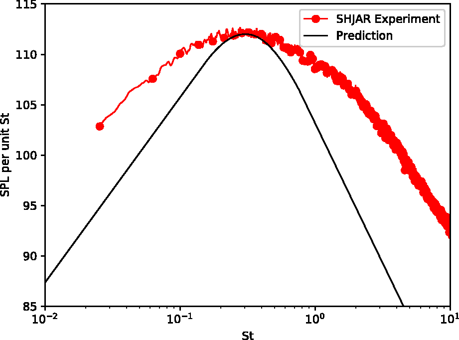
Prediction compared to measurement of SHJAR of a
The predictions are very similar to the large-scale similarity spectra proposed by Tam et al.
43
This is expected because the noise predicted is from a basis function designed to mimic measurements of large-scale structures or instability waves within the jet. This approach does not represent a total noise prediction method capable of predicting the total spectra accurately because it lacks a fine-scale mixing noise source. The purpose of the free-field predictions is to calibrate the prediction method for subsequent examination of the constructive interference pattern due to the acoustic-instability wave feedback mechanism. We have calibrated the coefficients in our model through comparison with the method of the large-scale similarity spectra of Tam et al.
43
and associated SHJAR experiments. The calibration is performed by adjusting the coefficients for the Md = 1,
Jet aeroacoustic impingement predictions compared with Messersmith
We now examine the experiment of Messersmith
30
and make predictions for comparison. Messersmith
30
conducted experiments of jets impinging on large flat plates at relatively short
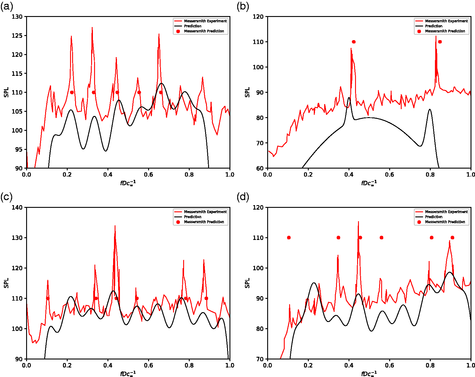
Predictions compared to measurements of Messersmith.
30
Impingement angle
Predictions of the location of amplification, using the approach of Messersmith,
30
are shown as circles. The predictions of Messersmith
30
do not include amplitude, and we have selected their amplitude to be 110 dB in each case for comparison purposes only. For this case, we evaluate gt using the mirror source technique, where the source is placed on the opposite side of a fictitious plane that is centered on the nozzle axis and at the corresponding distanced
Jet aeroacoustic impingement predictions compared with Worden et al.
We now examine the recent experiment of Worden et al.,
16
who conducted jet impingement studies at the Anechoic High-Temperature Jet Facility at Florida State University. A convergent-divergent nozzle with
Equation (22) is evaluated through iterations involving gt and updating
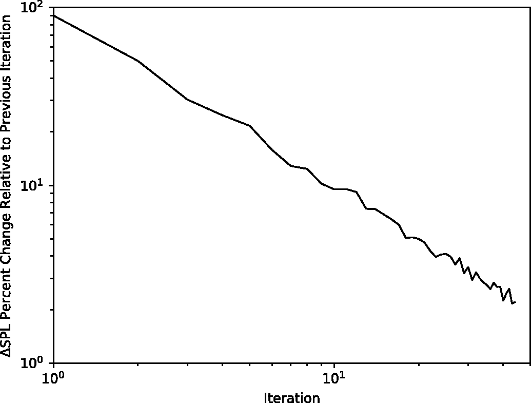
Prediction model convergence in terms of percentage change in ΔSPL versus previous iteration.
Measurements of Worden et al. 16 are shown in Figures 19 (unheated) and 20 (heated), respectively. The y-axis is SPL per unit St and the x-axis is St. Measurements are shown as lines with symbols and predictions using equation (22) are shown as solid lines of corresponding color. We predict the amplified pattern in the region of maximum SPL. Here, gt is calculated through the evaluation of equation (9), where a single edge is modeled that corresponds to the edge of the experiment. Note that at this radiation angle, the fine-scale mixing noise makes a contribution to the total noise, thus it appears that the model underpredicts the measured spectra. Predictions capture the Δf for both the unheated and heated jet amplification pattern. Predictions shown in Figure 20 over estimate the primary and secondary harmonic interference patterns and spectral widths.
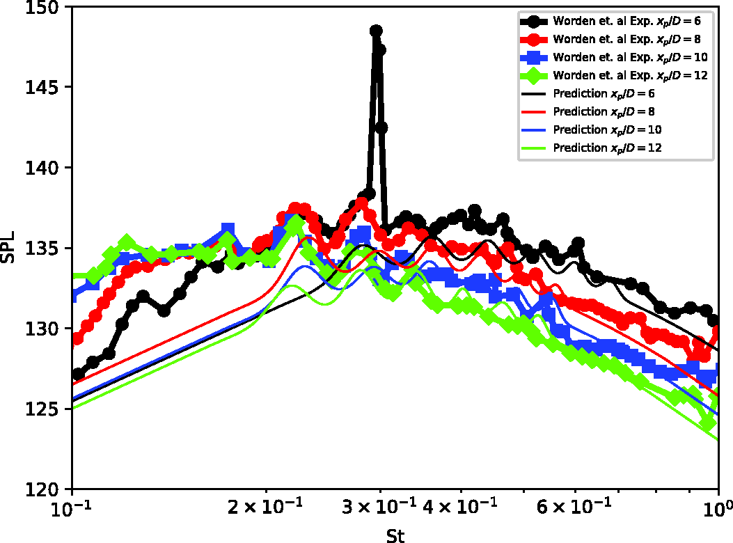
Predictions compared to measurements of Worden et al. 16 of an unheated on-design jet.

Predictions compared to measurements of Worden et al. 16 of a heated on-design jet.
Summary and conclusion
Jet structure interaction often involves the exhaust impinging on a blast deflector. Such flows are often present during rocket launch, impingement of engine exhaust on aircraft pylons or flaps, or aircraft take-off during carrier operations. The instability waves in conjunction with reflected waves can constructively interfere to create a “ripple” or constructive interference pattern of the acoustic pressure spectra. This feedback mechanism is modeled through construction of an instability wave basis function or large-scale structure model for an equivalent source of an acoustic analogy. A tailored Green’s function for a semi-infinite flat plate is used to model the deflector. The model is calibrated against static jets without reflections and then compared to two experimental datasets with reflections. The model is initially evaluated recursively to find the correct amplification of the instability wave basis function and then reevaluated to find the far-field acoustic pressure spectrum. Predictions compare favorably, often predict the correct frequencies of constructive interference, and often predict the correct spectral broadening near each interference frequency. The large-scale structure or instability model must be made more general, put on a firmer theoretical foundation, and linked to the underlying governing equations of fluid motion.
Footnotes
Authors’ note
Any opinions, findings, and conclusions or recommendations expressed in this material are those of the author(s) and do not necessarily reflect the views of the Office of Naval Research.
Declaration of conflicting interests
The author(s) declared no potential conflicts of interest with respect to the research, authorship, and/or publication of this article.
Funding
The author(s) disclosed receipt of the following financial support for the research, authorship, and/or publication of this article: S. A. E. Miller was supported by Office of Naval Research Grant N00014-17–1-2583 “Turbulent Statistics and Associated Acoustic Sources Near Shock Wave Shear Layer Interactions”, under the advisement of Steven Martens, John Spyropoulos, and Russell Powers. Alexander N Carr was supported by the University of Florida Herbert Wertheim College of Engineering Graduate School Preeminence Award.