



Abstract
This study establishes a statistical energy model for a vehicle to evaluate and optimize the acoustic performance of its firewall pass-through components. The “window method” was applied to calculate the contributions of the firewall assembly, dash inner, and individual pass-through components to overall sound transmission. The sound insulation performance and coverage of these components were optimized. Prototype samples were developed and validated under real-world operating conditions at 60 km/h. The optimized design reduced the sound pressure level in the driver’s right ear by 1.1 dB (A), improved the articulation index (AI) by 2.8%, and achieved spectral energy reductions of 1–2.9 dB (A). These findings provide valuable insights into the design and setting of acoustic performance targets for firewall pass-through components in future vehicle models.
Keywords
Firewall assembly is a critical system that prevents noise from the engine compartment (e.g., engine noise or noise from the electric motor and gearbox) from being transmitted into the vehicle interior.1–3 Its sound insulation performance plays a pivotal role in reducing the noise levels inside a vehicle and enhancing the interior sound quality. With advancements in the automotive industry and growing consumer demand for comfort, the requirements for vehicle noise, vibration, and harshness (NVH) performance have become increasingly stringent. The firewall assembly serves as one of the primary pathways through which engine compartment noise enters the vehicle interior, making its NVH performance a significant focus and challenge for original equipment manufacturers.4–7
The firewall assembly comprises not only the front metal sheet and insulation pad, such as the front and engine compartment insulation pads, but also various pass-through components. Historically, designers have often overlooked the sound insulation performance of these pass-through components, including brake pedal pass-throughs, wire harness pass-throughs, throttle pedal pass-throughs, steering column pass-throughs, refrigerant pipes, hot-water pipes, and fresh air ducts of air-conditioning systems. 8 These pass-through components substantially impact the overall sound insulation performance of the firewall assembly, significantly influencing both the interior noise and sound quality of the vehicle.
Research related to firewall materials includes vehicle SEA analysis methods and noise-source identification. Arjunan et al. 9 reported that acoustic metamaterials offer great potential in the areas of sound absorption, insulation, stealth, and imaging. Foulkes et al. 10 predicted the structure and air-transfer paths based on vehicle SEA simulation models by correcting the loss factor. Yang 11 characterized the acoustic absorption and insulation of polyurethane foam (PU) in vehicles using a whole-vehicle SEA model. Wang 12 used the SEA model of an entire vehicle to simulate the wind-tunnel test and analyze the wind-noise propagation characteristics. Techniques such as sound intensity identification13,14 and beamforming in a reverberation-anechoic chamber13,15–17 can identify weak points in a firewall assembly; however, they do not offer a detailed analysis of the differences in sound insulation performance across individual components.
To address this gap, we tested for the presence or absence of pass-through components in a reverberation-anechoic chamber and calculated their insertion loss. The results were incorporated into a statistical energy analysis (SEA) model of the entire vehicle. Using the “windowing method,” we computed the contribution rates of the firewall assembly, front insulation pad, and individual pass-through components to interior noise.
Optimization designs were then applied to the pass-through components that had the greatest impact on interior noise, enhancing their sound insulation performance and coverage. Additionally, vehicle testing validated improvements in the firewall assembly’s sound insulation performance and its impact on reducing interior noise. The proposed methodology accurately calculated the insertion loss of pass-through components and evaluated the contribution rates within the firewall assembly using a complete vehicle model. This approach holds substantial practical engineering value for optimizing the design of the pass-through components in modern vehicles.
Relevant principles
SEA statistical energy principle
The SEA method uses statistical models and energy power flow to represent the state of subsystems and their interactions. It simplifies noise issues by expressing them as energy exchanges between subsystems, which are then translated into sound pressure levels (SPLs) to quantify the noise intensity.
To establish an SEA model, the following conditions must be satisfied: (1) Linear system: The system must exhibit linear characteristics, with linear interactions between components. (2) Conservative system: The total energy within the system remains constant, meaning energy is conserved and flows between subsystems (3) Modal energy equilibrium: All modes within a frequency band possess equal energy (4) Reciprocity principle: For two coupled systems, the product of the loss factor and number of modes for each subsystem within a frequency band must be equal.
Figure 1 illustrates the energy analysis model for two systems. The power-flow relationship between the two systems is expressed as follows
7
: Energy analysis model of two systems.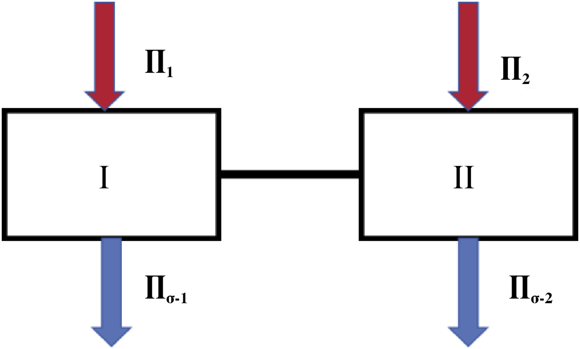


For a large system consisting of N subsystems, the power-flow equations can be expressed as follows:

Assuming that only subsystem K is externally excited, the energy stored in the i-th subsystem can be derived from equation (4):

From equation (4), the SPL of subsystem i in the target frequency band is determined as follows:

Sound insulation level of the firewall assembly
The firewall assembly includes components such as the front metal sheet, heat insulation pads, and pass-through components. During the digital design phase, spatial constraints lead to uneven thickness distribution and material inconsistencies in the front insulation pad. As a result, the subsystems display variations in transmission performance.
Typically, firewall components feature small transmission coefficients but large transmission surface areas, whereas pass-through components exhibit larger transmission coefficients and small transmission areas. 8
The overall transmission coefficient of the firewall assembly is expressed as

The sound insulation level (SIL) of the firewall assembly can be calculated by

Leaks and coverage
When the SIL is sufficiently high, it can be assumed that the material transmission coefficient is zero, whereas the transmission coefficient for the leakage areas is 1. For a leakage area of 0.001%, the STL can be calculated using equation (8). The STL of the front system will not exceed 50 dB, even if the leakage area is extremely small. When the leakage area increases to 0.01%, the STL of the front system will not exceed 40 dB. If the leakage area reaches 1%, the STL of the front system will not exceed 20 dB.

If the transmission coefficient is 0.000001 and the coverage rate is 100%, applying equation (8) yields an STL of 60 dB. When the coverage rate decreased to 99.9%, the transmission coefficient of the sheet metal increased to 0.001, and the STL decreased to 57 dB, a reduction of 3 dB. With a coverage rate of 99%, the STL decreases to 9.6 dB, a reduction of 10.4 dB. At a 99% coverage rate, the overall SIL of the front system cannot exceed 50 dB even if the sound insulation performance of the subsystems is improved. 8
Model matching
Using an electric vehicle as a case study, the SEA model of the complete vehicle consists of 218 panels and 60 acoustic cavities. Based on the vehicle’s structural layout and the distribution of its acoustic package, the body panels were organized into distinct subsystems.
System parameters were defined using factors such as panel density, thickness, Young’s modulus, and Poisson’s ratio of the panels.
20
Additional parameters, including the tested damping loss factor, acoustic performance (such as absorption coefficient and STL), and the modal density of complex panels were used to define the acoustic cavities. External acoustic loads were applied to the corresponding acoustic cavities under various operating conditions, as shown in Figure 2. SEA model of the entire vehicle.
Under actual operating conditions, the tested acoustic source loads were applied to the complete SEA model to simulate vehicle interior noise. These results were then compared with the experimental data (Figure 3). The test was conducted using a dynamometer in a semi-anechoic chamber, and a microphone was placed in the driver’s right ear. At speeds of 60 km/h and 100 km/h, the simulation and experimental results showed deviations ranging from 0.2 to 2.3 dB(A), well within the required range of ±3 dB(A).
21
The overall trends were consistent, indicating a strong agreement between simulation and experimental data. This validation confirmed the model’s reliability for analyzing the acoustic package of the entire vehicle. Comparison between simulation and experimental results.
Analysis and calculations
SIL of pass-through components
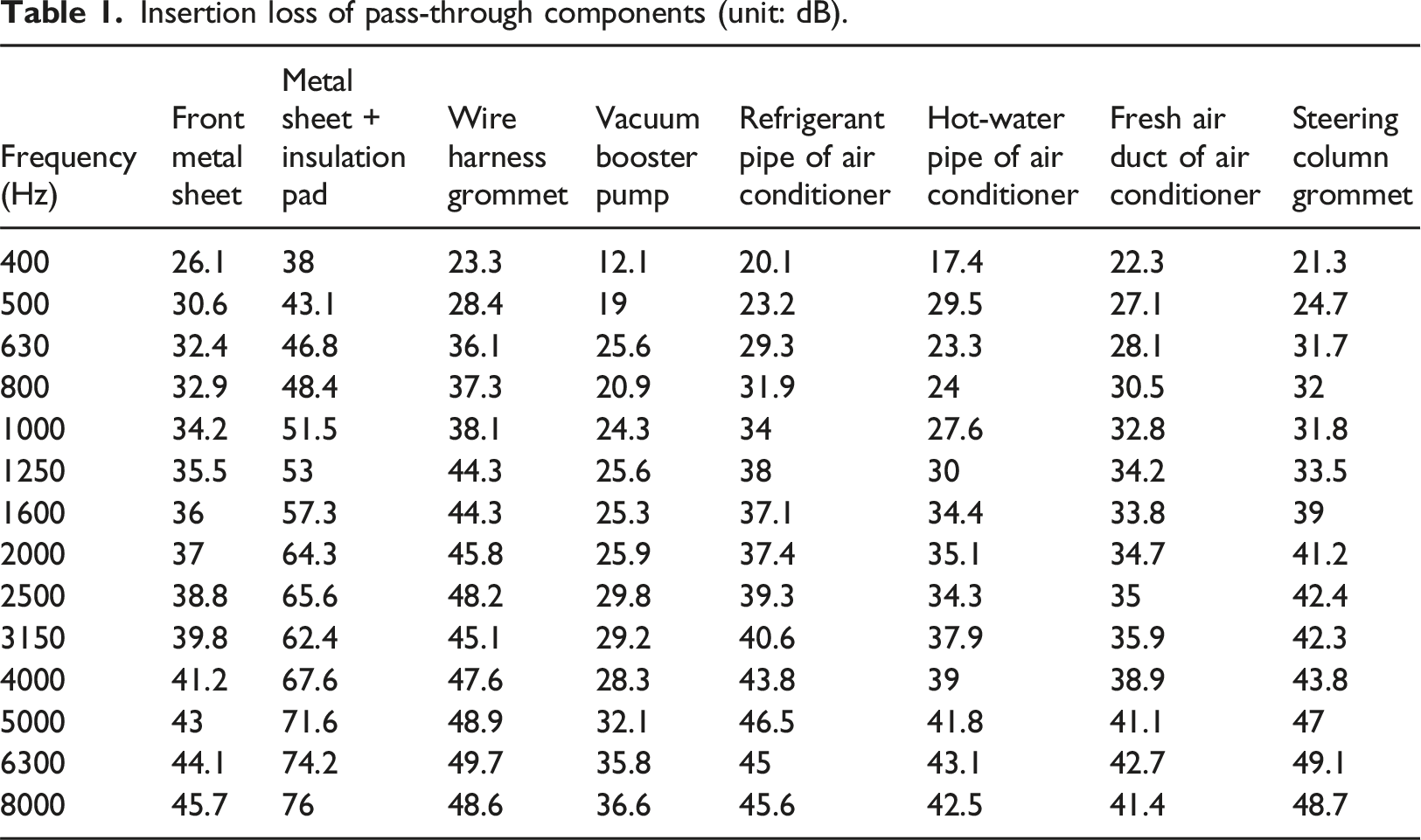
The SIL of pass-through components, such as wire harness grommets, vacuum booster pumps, and steering column grommets, cannot be directly simulated using VA-One software. Instead, these values must be determined through measurements taken in a reverberation-anechoic chamber setup.
The firewall assembly was positioned between the reverberation and anechoic chambers, as shown in Figure 4. A spherical sound source in the reverberation chamber emitted white noise, and four microphones measured the SPL. On the anechoic side, the sound intensity probe was scanned along an S-shaped trajectory, perpendicular to the firewall assembly. The insertion loss (STL) was calculated using equation (9)
22
: Installation position of the front system.

Insertion loss of pass-through components (unit: dB).
Impact of pass-through components on vehicle interior noise
Using the SEA model of the entire vehicle (under operating conditions: 60 km/h), the open and closed states of the pass-through components are compared in Figure 5. SPL in the head cavity of the driver showed marked differences between the two states. SPL fluctuations of 0.5–1.6 dB (A) observed in the 400–1250 Hz frequency range, while 0.7–2 dB (A) fluctuations occurred in the 5000–8000 Hz range. These findings demonstrate that pass-through components significantly influence vehicle interior noise, owing to their low SILs and limited coverage. Vehicle interior noise with pass-through components open versus closed.
Contribution rate analysis of firewall pass-through components
Using the windowing method in VA-One software, all vehicle panels, including their acoustic insulation and external acoustic loads (operating condition: 60 km/h), were sealed. Subsequently, only the panel and acoustic load of interest were activated to calculate the interior SPL in Pa2. The results were converted into a contribution rate (α) using equations (10) and (11).
23


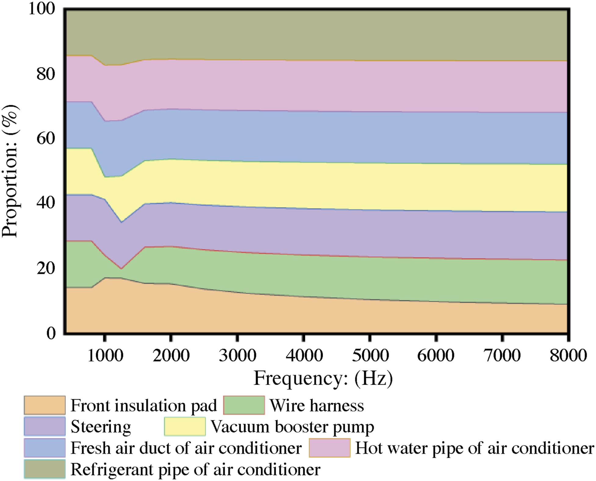
The firewall assembly represents approximately 20% of the total energy within the vehicle system, as illustrated in Figure 6. Within this assembly, the front insulation pad accounted for only a minor share of the energy, while the main contributors were the pass-through components (Figure 7). To improve the overall sound insulation performance of firewall assemblies, efforts should focus primarily on enhancing the pass-through components. Contribution rate of the firewall assembly. Contribution rate of pass-through components.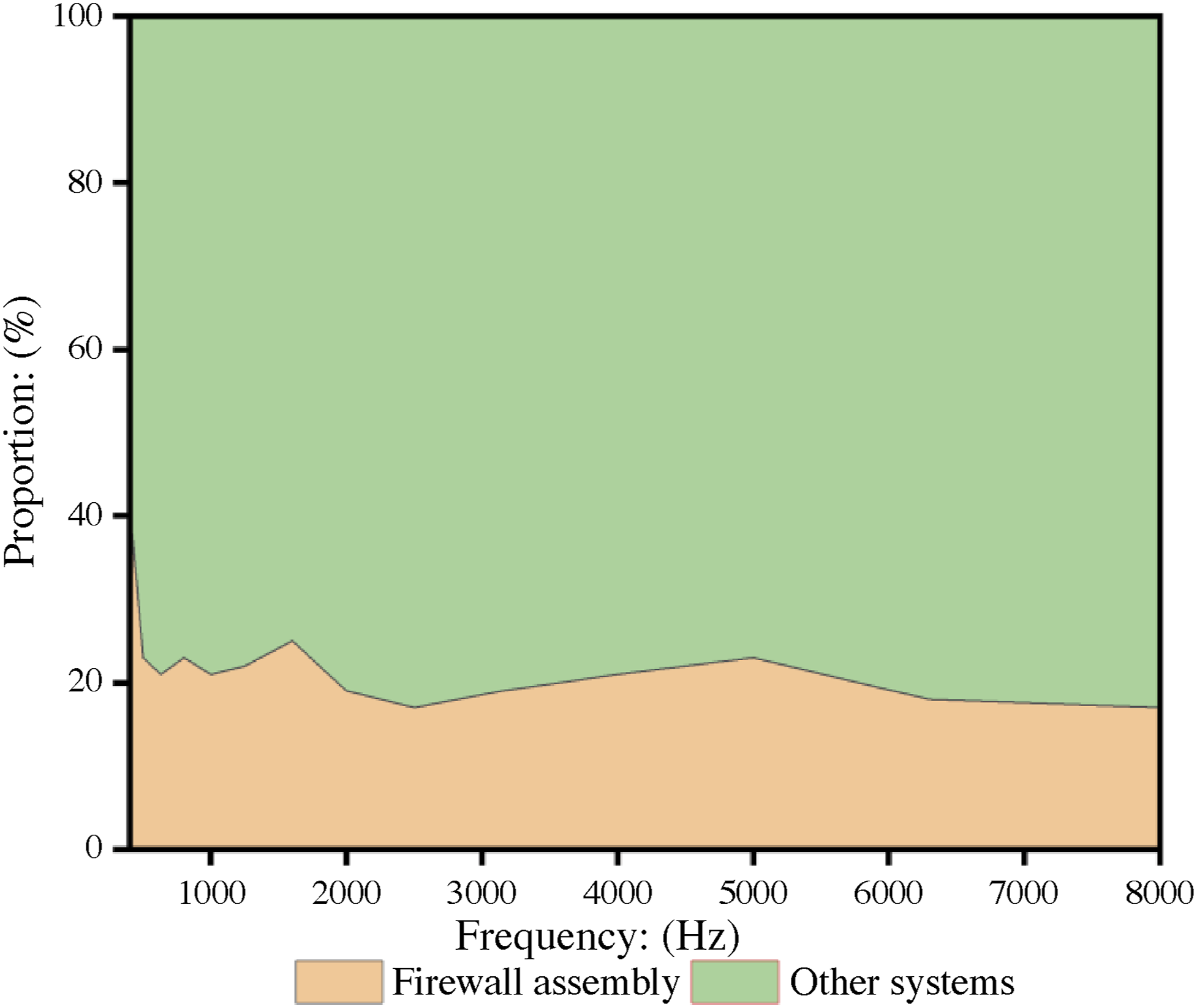
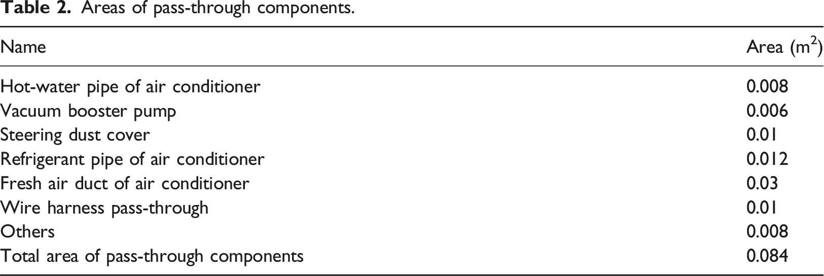
Firewall pass-through component areas
Areas of pass-through components.
Design optimization
Improving the sound insulation performance of the firewall assembly mainly involves enhancing both the insulation properties and coverage of the pass-through components.
Improvement of wire harness grommet performance
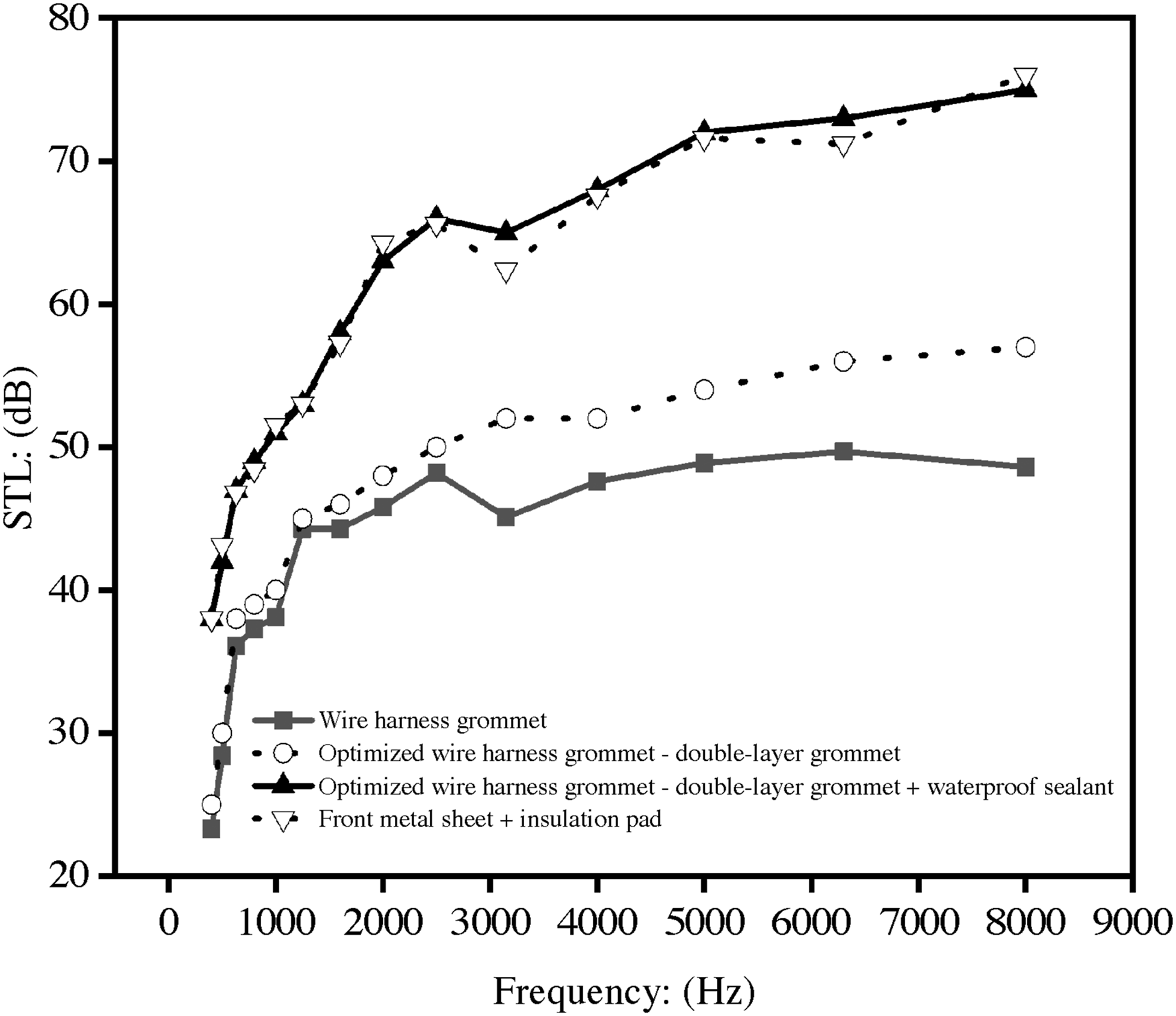
The original wire harness grommet was a single-layer (4 mm thick, as shown in Figure 8(a)). This configuration posed a risk of leakage and exhibited a low sound insulation performance. To address these issues, a double-layer grommet (both 4 mm thick, as shown in Figure 8(b)) was developed. However, sound insulation testing in a reverberation-anechoic chamber revealed that the SIL of the optimized grommet did not match the performance of the metal sheet combined with the insulation pad. To resolve this issue, a waterproof sealant was injected into the double-layer grommet (Figure 8(c)). This enhancement improved the sound insulation performance, achieving parity with the metal sheet and insulation pad, as shown in Figure 9. Optimization of wire harness grommet. STL comparison of optimized wire harness grommet.
Optimization of steering column grommet performance
The original steering column grommet was a single 10 mm thick rubber layer. A 5 mm gap to the front insulation pad contributed to inadequate sound insulation compared to the metal sheet and insulation pad combination (as shown in Figure 10). STL comparison of optimized steering column grommet.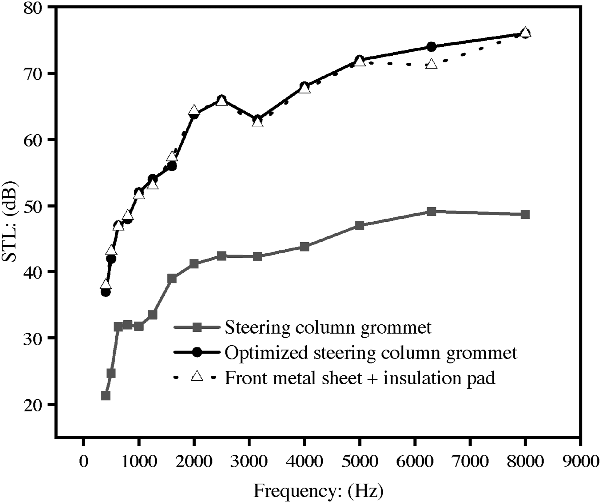
The optimized design, shown in Figure 11, incorporated a double-layer grommet composed of ethylene propylene diene monomer (EPDM) rubber. One layer contacted the metal sheet, while the other was connected to the front insulation pad, improving the overall coverage. Additionally, polyurethane foam was inserted inside Grommet 1 to enhance insulation. After optimization, the steering column grommet achieved sound insulation performance of the equivalent metal sheet and insulation pad combination, as shown in Figure 10. Optimization of steering column grommet.
Improvement of pass-through performance for refrigerant and hot-water pipes of the air conditioner
The pass-through for the refrigerant and hot-water pipes accounted for areas of 0.012 and 0.008 m2, respectively, comprising a significant portion of the total pass-through area. To optimize these, the two pass-throughs were combined into a single air-conditioning expansion valve with a reduced area of 0.015 m2, maximizing coverage and minimizing the whole size.
The grommet for this combined pass-through employed a material combination of EPDM and polyurethane (PU) foam, similar to the steering column grommet. One layer was covered with a metal sheet, and the other with an insulation pad to maximize coverage and improve sound insulation. Post-optimization testing demonstrated sound insulation performance comparable to that of the metal sheet and insulation pad combination, as shown in Figure 12. STL comparison of air conditioner pass-through optimization.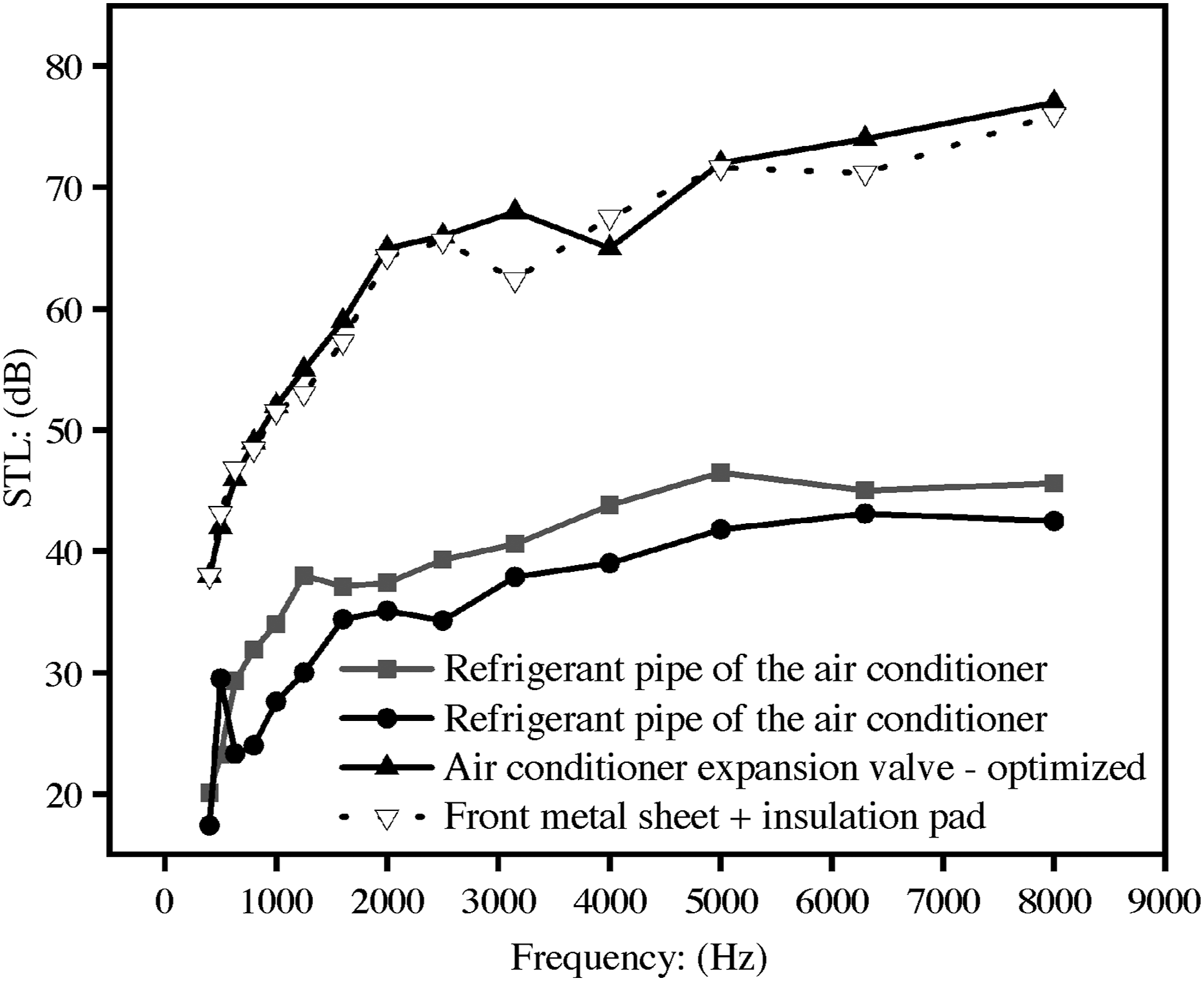
Design optimization principles for other pass-throughs
Additional pass-throughs—such as those for vacuum booster pumps, fresh air ducts of air conditioners, and brake pedals—also require optimization to achieve a sound insulation performance equivalent to that of the metal sheet and insulation pad combination.24,25 The optimization principles are as follows: (1) Test prototype samples to ensure that the performance matches the metal sheet + insulation pad level. (2) Reduce the pass-through area wherever feasible, such as decreasing the size of the fresh air duct. (3) Implement designs in which one side is covered by a metal sheet and the other by an insulation pad, ensuring full coverage and eliminating leakage. (4) Prevent hard contact between components, such as the vacuum booster pump and metal sheet, because gaps can lead to leakage. Use EPDM foam at contact points to address this issue.
Optimization validation
The optimized pass-through components were installed on the firewall assembly, and tests were carried out in a reverberation-anechoic chamber both with and without the components. Insertion losses for the optimized designs were calculated and integrated into the simulation model for further evaluation. Prototype samples of the optimized components were also fabricated and installed on a test vehicle to assess their performance under real-world conditions.
Vehicle interior noise simulation analysis
A simulation analysis was performed under operating conditions of 60 km/h, focusing on the driver’s head cavity response. As shown in Figure 13, the optimized state exhibited a noise reduction of 0.1–1.7 dB (A) compared with the original configuration, indicating a substantial improvement in interior noise levels. Comparison of vehicle interior noise in the original and optimized states.
Real vehicle validation
The test vehicle was first evaluated in its original configuration and then tested using the optimized pass-through components. The test was conducted at an operating speed of 60 km/h in a semi-anechoic chamber.
SPL and AI.

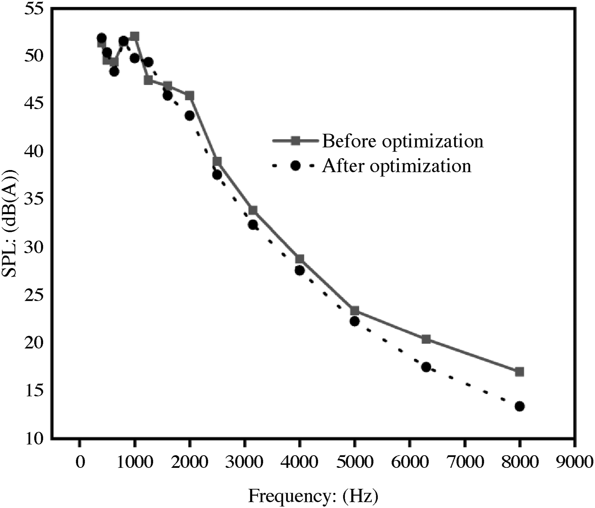
Spectral energy comparison.
Conclusion
Through structural optimization, the sound insulation performance of pass-through components was significantly enhanced, which improved the overall sound insulation performance of the firewall assembly. These advancements have reduced vehicle interior noise, thereby enhancing the overall vehicle quality. The findings provide a solid basis for the design and target setting of the firewall pass-through components of new vehicle models. In vehicle design, the structure of each pass-through component may differ; however, the design ideas and principles remain the same. In addition, the effect of wind noise on the firewall assembly is not considered.
Footnotes

Author contributions
Research on the conceptualization, experimental testing, and simulation methods of the article - Xu Linqian. Sound insulation performance test of pass-through - Qian Cairang, Zhu Shengzhi. Building the Whole- Vehicle SEA Model - Du Bin. Optimization and verification of pass-through - Yin fen. All authors have approved the final version of the manuscript.
Declaration of conflicting interests
The author(s) declared no potential conflicts of interest with respect to the research, authorship, and/or publication of this article.
Funding
The author(s) disclosed receipt of the following financial support for the research, authorship, and/or publication of this article: this work was supported by the program, supported by the Qinghai Provincial Department of Science and Technology (2023-QLGKLYCZX-019); Research Cultivation Program for Extension of Papers by New Faculty (Doctoral/Master’s Degree) at Qinghai Institute of Technology (2023011wys027).
Ethical statement
Data Availability Statement
Data sharing is not applicable to this article, as no datasets were generated or analyzed during the current study.