
Abstract
Treatment for severe scoliosis is usually attained when the scoliotic spine is deformed and fixed by implant rods. Investigation of the intraoperative changes of implant rod shape in three-dimensions is necessary to understand the biomechanics of scoliosis correction, establish consensus of the treatment, and achieve the optimal outcome. The objective of this study was to measure the intraoperative three-dimensional geometry and deformation of implant rod during scoliosis corrective surgery.
A pair of images was obtained intraoperatively by the dual camera system before rotation and after rotation of rods during scoliosis surgery. The three-dimensional implant rod geometry before implantation was measured directly by the surgeon and after surgery using a CT scanner. The images of rods were reconstructed in three-dimensions using quintic polynomial functions. The implant rod deformation was evaluated using the angle between the two three-dimensional tangent vectors measured at the ends of the implant rod.
The implant rods at the concave side were significantly deformed during surgery. The highest rod deformation was found after the rotation of rods. The implant curvature regained after the surgical treatment.
Careful intraoperative rod maneuver is important to achieve a safe clinical outcome because the intraoperative forces could be higher than the postoperative forces. Continuous scoliosis correction was observed as indicated by the regain of the implant rod curvature after surgery.
Introduction
Adolescent Idiopathic Scoliosis (AIS) is a spinal pathology in which the etiology remains uncertain. The disease is characterized as a lateral deformity of the spine in three-dimensions accompanied by axial rotation of the vertebrae. Treatment for severe AIS often requires surgical intervention. Surgical treatment is accomplished when the scoliotic spine is deformed into a desired shape by corrective rods and screws attached to the vertebrae. Although the introduction of malleable rods and pedicle screws resulted to a more sophisticated system which addressed scoliosis correction in three-dimensions, decision-making became more complex. More extensive planning of implant rod curvature and length, and fixation level of screws also became imperative in achieving the desirable clinical outcome. Aubin et al. and Robitaille et al. reported a large variability of the preoperative instrumentation strategies within the group of experienced spine surgeons [1,2]. Until now, the biomechanics of scoliosis correction is not yet fully understood. There is still a lack of consensus as reflected by the differences of surgical strategies specifically on what implant rod shape, rod length, number of screws and fixation levels would be best to achieve the optimal clinical outcome. Understanding the biomechanics of scoliosis correction could help us determine the optimal approach which can be applied for a certain case of spinal deformity [3,4].
In an attempt to gain better understanding on the underlying biomechanics of scoliosis correction, the intraoperative effects of instrumentation systems and strategies during scoliosis surgery were investigated. Intraoperative tracking of the trunk movement during scoliosis surgery using electromagnetic system and infrared cameras combined with markers mounted to the trunk were reported [5,6]. They monitored the intraoperative changes of the trunk geometry induced by the surgical maneuvers during posterior approach of instrumentation. Intraoperative tracking of the trunk motion using these methods contributed to a better understanding of the effects of instrumentation systems on the changes or correction of the trunk geometry. However, these methods require placement of markers to the trunk which may lead to increased time of the surgical procedure. Vertebral motion measurements were also performed using a custom-made spinal instrument attached directly to the vertebra. The custom-made instrument is drilled and fixed into the spine during scoliosis surgery [7–9]. These methods helped surgeons understand how various instrumentation systems are effective in correcting the deformity in three-dimensions by evaluating the movements of the vertebrae during correction maneuver. Drilling of bone, which is also a technically demanding procedure, however, became necessary to insert and fix the custom-made instrument during the assessment of vertebral motion segments. All the same, these systems can increase the surgical time and could pose surgical operation risks due to additional procedures. Thus, a more simple method that could assess the scoliosis correction intraoperatively without significantly affecting the surgical operation is essential in understanding the biomechanical effects of scoliosis fixation systems.
The evaluation of scoliosis correction in three-dimensions requires an assessment of the both frontal and sagittal planes. Assessment of the frontal plane correction can be perceived easily since this plane is visible during scoliosis surgery, i.e. particularly with the posterior approach. Conversely, sagittal plane assessment is difficult because this cannot be seen directly during the surgical operation and may require advanced imaging tools and methods. The postoperative radiographs of many studies indicate that the implant rod curvature represents also the spine shape [10–17]. Thus, the implant rod geometry can be used also to assess the scoliosis sagittal correction not only postoperatively but also intraoperatively.
The main objective of this study was to measure the intraoperative three-dimensional geometry and deformation of implant rod during scoliosis corrective surgery. The implant rod geometry before implantation and after surgery was also measured to compare the changes with the intraoperative implant rod geometries. To quantitatively evaluate the deformation of rod, the implant rod angle of curvature between the implant rod ends was computed from the implant rod geometry. The implant rod angle of curvature was also used to assess the scoliosis correction.
Materials and methods
Upon approval of the university and hospital research ethics committee, three Adolescent Idiopathic Scoliosis (AIS) patients were enrolled and underwent surgical operation. Informed consent was thoroughly explained and obtained from each patient. Implant rods of six mm diameter (∅ 6 mm) and polyaxial pedicle screws (USS II Polyaxial, Synthes GmbH, Switzerland) were implanted to the concave (left rod) and convex side (right rod) of the scoliosis deformity, in Fig. 1(leftmost)(middle). The implant rod shape and length vary with each patient and decided by the attending surgeon. All implant rods were pre-bent only at a single plane.
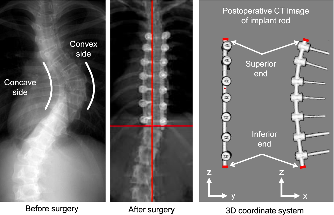
Scoliotic spine before and after surgery when fixed by rods at the concave and convex side of the deformity (leftmost and middle). Implant rod geometry obtained by CT scan and the three-dimensional coordinate axes reference (rightmost).
The screws and rods were surgically implanted following the simultaneous double rod derotation technique. In this technique, two rods for the concave and convex side of the deformity were inserted into the polyaxial screw heads. The polyaxial screws were temporarily not fully tightened to allow the rod to rotate and move freely inside the screw head. The rods were simultaneously rotated (about 90 degrees) thereby transferring the previous curvature of the implant rod from the coronal plane to the sagittal plane. Further details of the surgical technique can be found in the previous paper [13].
The experimentally validated numerical method proposed by Salmingo et al. to reconstruct the intraoperative three-dimensional geometry of implant rod using two cameras was utilized [18]. The images were obtained at the two intraoperative phases of scoliosis surgery, i.e. before rotation of rods or when the rods have just been inserted into the screw heads, and after rotation of rod about 90 deg. or when the screws were already fully tightened.
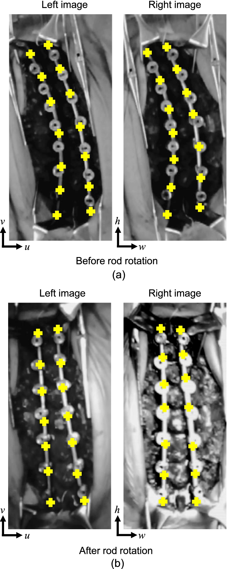
Intraoperative images obtained by the dual camera system during scoliosis surgery. The left and right rod of each image was the implant rod placed at the concave and convex side of spinal deformity, respectively.
Image processing algorithm was programmed using computer software (MATLAB R2010b, Massachusetts, USA). The bases of the two cameras were set coplanar and the optical axes were obliquely positioned to each other at an included angle. The included angle (41–42 deg.) was adjusted intraoperatively to achieve better image coverage. Intraoperative pairs of images at different views were obtained by the dual camera system, i.e. before rotation of rods (Fig. 2(a)) and after rotation of rods (Fig. 2(b)). The rod at the left side of each image was the spinal rod at the concave side of the deformity. The rod at the right side of each image was the implant rod at the convex side of the deformity. Points (n = no. of points) measured in pixels (cross marks) were selected from the most inferior to the most superior end along the central axes of the implant rods as
Each implant rod curvature on the left and right pair of images represented by points
The coordinate system was established for the three-dimensional geometry of implant rod, in Fig. 1(right). The x–z plane was set as the principal bending plane since the implant rod is always pre-bent at a single plane. This plane also corresponds to the sagittal plane after rotation of rods. The y–z plane is orthogonal to the x–z plane. The most inferior end of the implant rod was set as the origin
Three-dimensional coordinate rotation was performed to translate the most superior end of the implant rod such that it coincides the z-axis and to transform the principal bending plane to the x–z plane or to the reference coordinate axes and planes. The three-dimensional geometry of implant rod was expressed as parametric equations in terms of unit vector t
The actual length of rod
The calibration scale k can be computed using Eq. (6). This parameter is also equal to the resolution of the measurement expressed in mm/pixel,
The three-dimensional coordinates of implant rod in millimeters can be computed by the equation
Furthermore, the implant rod geometry before implantation was measured by a conventional flatbed scanner before insertion to the screw heads. The implant geometry after surgery (one week maximum) was obtained postoperatively by CT scanner (Aquilion 64 CT Scan, Toshiba Medical Systems Corporation, Japan).
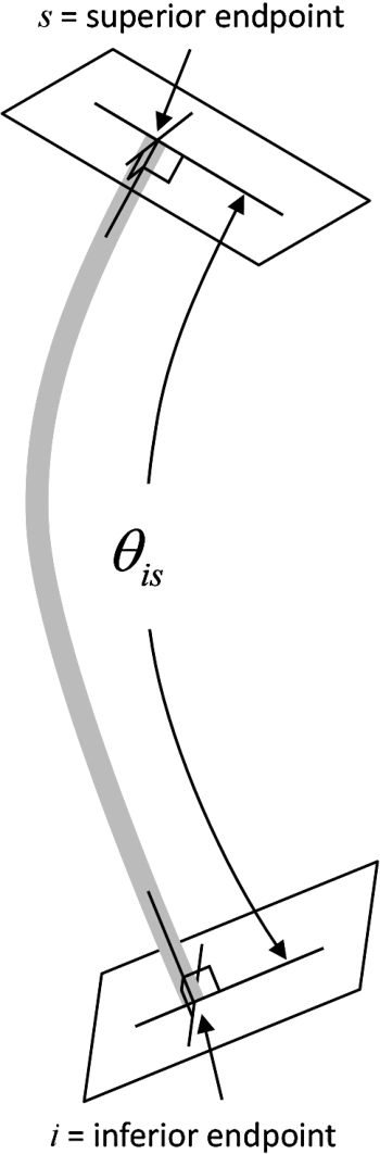
Implant rod angle of curvature.
The magnitude of implant rod deformation was evaluated using the angle of curvature
The implant rod angle of curvature was calculated as the angle of the two three-dimensional tangent vectors formed between the normals of the implant rod ends. The angle
Scoliosis correction assessment
Since it was already shown that the implant rod curvature constitutes also the sagittal curvature of the spine within its length, the implant rod angle of curvature was used to evaluate the scoliosis correction. The implant rod angle of curvature obtained in this study and the average thoracolumbar curvature of healthy adolescents (normal curvature) at the sagittal plane established by previous studies were used for comparison.
Range of fixation, normal curvature of the spine, length of rod and implant rod degree of curvature of each scoliosis patient at the concave and convex side of deformity
Range of fixation, normal curvature of the spine, length of rod and implant rod degree of curvature of each scoliosis patient at the concave and convex side of deformity
Mac-Thiong et al. measured the physiological thoracolumbar curvature of healthy adolescents at the sagittal plane [19]. The individual curvature of each vertebra level was also determined because the instrumented/fixation level of each patient differs from each other. The individual curvature for each vertebra level was approximated using the ratio of each height of vertebra [20]. The normal spine sagittal curvature between the corresponding fixation levels of each patient is listed in Table 1. For each patient, the extreme fixation level of concave and convex side is the same for both sides. Desirable correction is attained when the postoperative implant rod angle of curvature is the same with the normal spine sagittal curvature at the corresponding fixation level. Thus, assessment of the scoliosis correction of the sagittal curve could be determined by the angle difference.
Implant rod three-dimensional geometry
The pair of images that includes the implant rod shapes was obtained at the different phases of scoliosis treatment, i.e. before implantation, before rotation of rod, after rotation of rod, and after surgery. The implant rod length at the concave side of each patient was 218 mm, 188 mm and 215 mm for patient 1, patient 2 and patient 3, respectively. The implant rod length at the convex side of each patient was 232 mm, 188 mm and 239 mm for patient 1, patient 2 and patient 3, respectively. The images were analyzed to measure the three-dimensional implant rod geometry. Figure 4 shows the three-dimensional implant rod geometry of the three patients during scoliosis surgery. To standardize and better understand the three-dimensional geometry and deformation of spinal rod, a 3D coordinate rotation was performed to translate the most superior end of the implant rod such that it coincides the z-axis and to transform the principal bending plane to the x–z plane which represents also the sagittal plane. The figures at the left side show the three-dimensional implant rod geometry at the concave side of deformity. The three-dimensional geometry of the implant rods at the convex side of deformity are shown at the right side. The implant rod geometry before implantation, before rotation of rod, after rotation of rod, and after surgery are colored as black, green, blue, and red, respectively. All rods were not significantly deformed in y–z planes, i.e. the deformation was small to be detected.
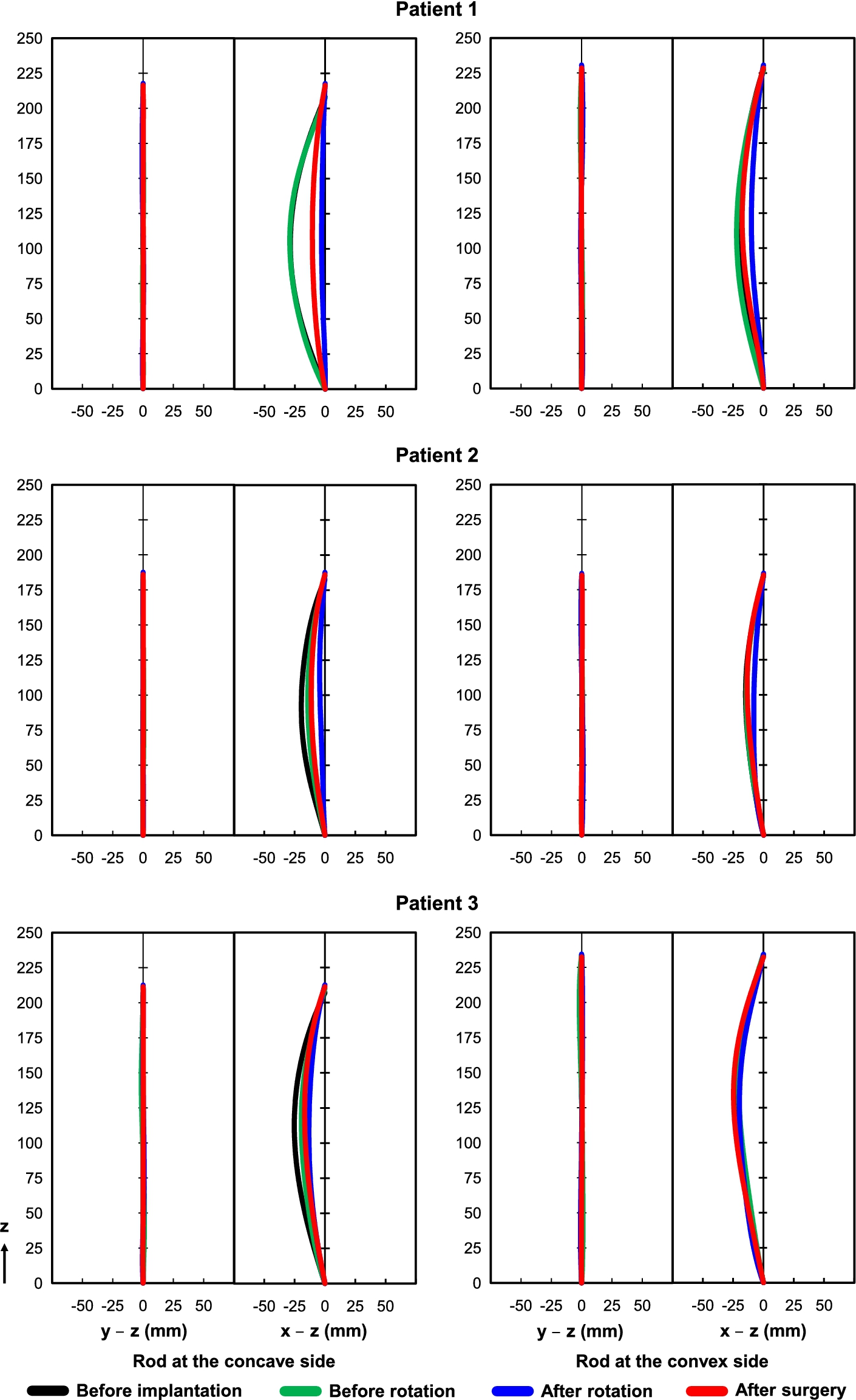
Three-dimensional implant rod geometry at the concave and convex side of deformity during and after scoliosis surgery.
The x–z plane shows the significant changes of rod geometry at different phases of the surgical procedure. There was a slight difference between the geometry of implant rod before implantation and before rotation of rod. This is the time when the rod has just been inserted into the heads of implant screws or rotation maneuver was not yet performed. The implant rod tended to straighten during and after the surgical operation from its original shape.
The implant rod angle of curvature was used to quantitatively evaluate implant rod deformation. The unit of angle is expressed in degrees. The implant rod angle of curvature before implantation, before rotation of rod, after rotation of rod, and after surgery of each scoliosis patient for both concave and convex sides is listed also in Table 1.
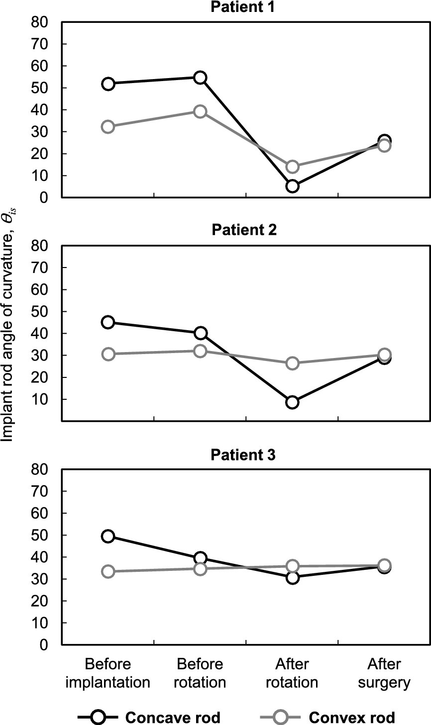
Implant rod angle of curvature of each scoliosis patient.
Figure 5 shows the implant rod angle of curvature of each patient. The angle of curvature of the implant rod at the convex side did not have much deformation except on patient 1 during after rotation of rod. The average difference between the implant rod angle of curvature before rotation and before implantation of rod for both concave and convex side was −0.4 deg. (range: −10 deg. to 7 deg.). For all patients, the highest deformation or decrease of implant rod angle of curvature was observed during after rotation of rod having −20 deg. in average (maximum: −47 deg. obtained from patient 1). This was computed as the difference between the angle of curvature after rotation and before implantation of rod. The implant rod angle of curvature at the concave side regained after surgery in all patients. The implant rod angle of curvature for both sides increased or regained by 10 deg. in average (range: 0 deg. to 21 deg.), i.e. from after rod rotation to after surgery.
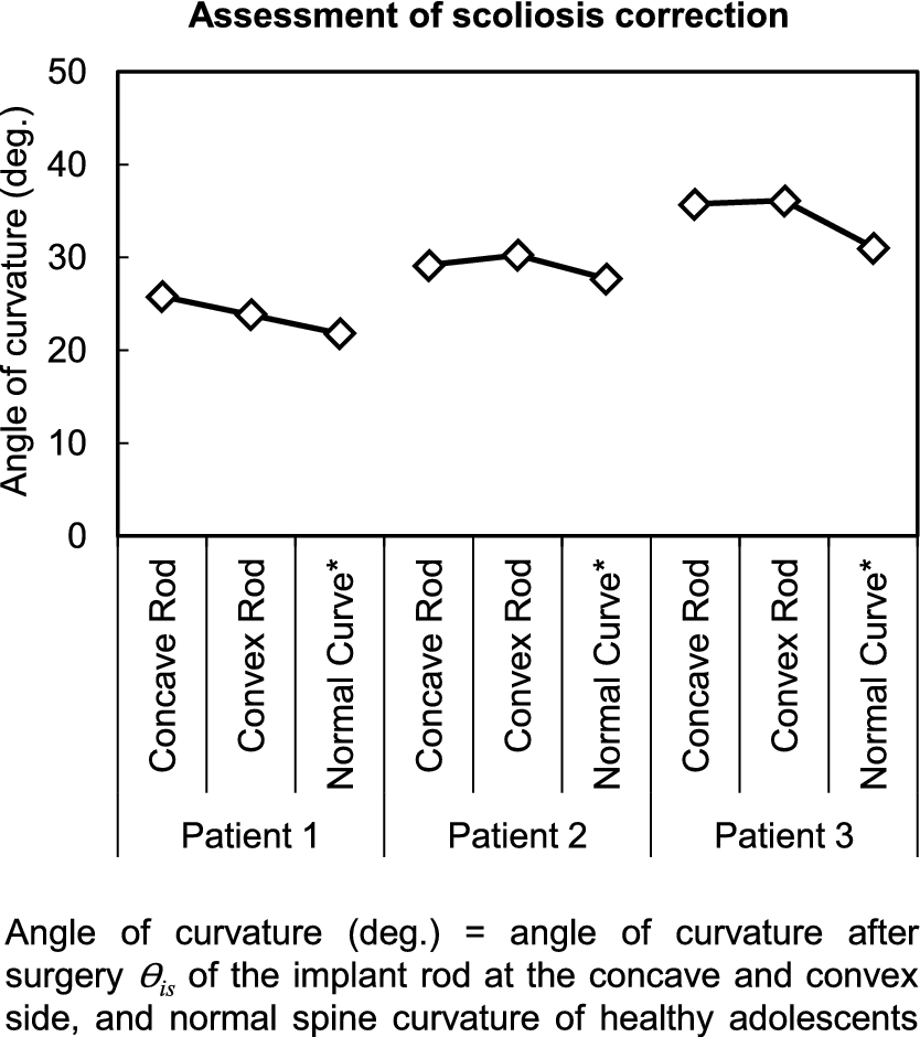
Desirable correction is achieved when the implant rod angle of curvature is the same with the thoracolumbar curvature of normal or healthy adolescents. The normal thoracolumbar curvature of healthy adolescents obtained by previous studies at the corresponding fixation level of each patient is listed in Table 1. The normal curvatures for the concave and convex sides were the same since the most inferior and superior fixation level of each patient were also the same for both sides. For all patients, there was only a small deviation (maximum was only 5 deg., rod at the convex side of patient 3) from the normal curvature for both concave and convex sides, in Fig. 6. The results indicate that desirable sagittal correction was achieved and regain of implant rod curvature after rotation of rod was beneficial in obtaining the normal kyphosis of scoliosis patients.
Discussion
Understanding of the biomechanics of scoliosis correction is important because until now the optimal scoliosis correction is still difficult to attain. Surgical parameters specifically the shape and length of implant rod, location of fixation levels and surgical technique still vary dependently on surgeons’ experiences and preferences. In fact, there is no consensus yet on what surgical strategy can be applied to a certain scoliosis case and achieve the optimal clinical outcome. Furthermore, in vivo implant rod deformation could alter the correction outcome primarily at the sagittal plane. Thus, it is imperative that the three-dimensional changes of implant rod geometry shall be measured during and after scoliosis surgery.
For all cases, there was a small difference between the geometry of implant rod before implantation and before rotation. This suggests that the corrective forces acting on the rods were minimal. This is because the rods were just inserted into the screw heads and the correction maneuver or rotation of rod has not been initiated yet. Conversely, the rods specifically at the concave side tended to straighten after rotation of rod, Fig. 4. The significant decrease of implant rod curvature implies that the forces carried by the spinal rods were also high. The goal of scoliosis correction by rod rotation maneuver is to transfer the curvature of implant rod at the coronal plane (Fig. 2(a)) to the sagittal plane by rotating the rods approximately 90 deg. Thus, a significant amount of corrective forces are required to displace the scoliotic spine structure during the rod rotation maneuver. The results also show that the rod at the convex side did not have significant deformation as compared to the concave side. This could be explained by the inherent morphology of the scoliotic spine. Previous studies showed that eccentric loads cause the spinous process to rotate towards the concave side of the scoliosis deformity and thus increasing also the required displacement of correction on that side [21,22].
The rod curvature tended to regain a week after surgery which subsequently increased the kyphosis curve. The increase of implant rod curvature might be due to the effects of body weight after surgery wherein patients began doing postoperative activities such as standing, walking and etc. The results also support the fact that the body weight increases the curvature of the spine during standing position [23,24].
The angle of curvature revealed that the implant rod at the concave and convex side was the same after surgery even though it was pre-bent initially using different curvatures before implantation. Furthermore, it can be also noticed that despite of various degree of deformations, i.e. before rotation and after rotation of each case, the angle of curvature of both sides still tended to converge after surgery. The results imply that there is an existing compensatory mechanism in the spine that attempt to equalize the changes in both sides. A further study involving more patients is necessary to elucidate the mechanism of these findings.
To the best of our knowledge, this is the first time that the intraoperative three-dimensional geometry of implant rod was measured quantitatively during scoliosis surgery. Previous studies performed finite element modeling of the scoliosis surgical procedure [25–27]. However, rod deformation was not considered in their analyses. This study shows various implant rod deformation patterns observed at different phases of surgery. From a mechanical point of view, if rod deformation is not considered in finite element analysis or being a rigid body model, the magnitude of computed forces will be high and unrealistic. Indeed the maximum force obtained by Aubin et al. was 956 N that was high enough and should have brought deformation of rod during scoliosis surgery [25]. Conversely, recent finite element studies show that the magnitudes of corrective forces acting on the deformed implant rods were not so high and the maximum value was just less than half of the previously reported maximum value, i.e. 439 N only [28,29]. Hence, deformation of implant rod should not be neglected in order to obtain more realistic results. The implant rod deformation is related to the magnitude of corrective forces acting on the spine in vivo. The magnitudes of corrective forces imply that the intraoperative phase requires more attention for preventing implant rod breakage or screw pullout during scoliosis surgery. Thus, careful intraoperative rod maneuver and planning is important to achieve a safe and optimal clinical outcome.
Conclusions
In this study, we showed that the implant rod shape could influence the clinical outcome because implant rod deformation could alter primarily the curve and sagittal balance. Implant rod deformation is inherent during scoliosis surgery as a consequence of corrective forces required to correct the scoliosis deformity. The highest rod deformation was found after the rotation of rods implying that the intraoperative forces were higher than the postoperative forces. Also, the regain of the implant rod curvature after surgery reveals that continuous correction is possible in the treatment of spinal deformities.
Footnotes
Acknowledgement
This study is partially supported by the fund of AOSpine Japan.
Conflict of interest
All authors were fully involved in the study and preparation of the manuscript. We certify that the current submission is original and is not submitted nor under review elsewhere. No benefits in any form have been or will be received from a commercial party related directly or indirectly to the manuscript.
Author note
The device mentioned in this paper is approved by the FDA and corresponding national agency for this indication.