
Abstract
Background:
In an early design stage of ship and propeller or in a propeller retrofit case one may consider a pre-swirl stator (PSS) to recover rotational energy.
Objectives:
A model for the working principle of a PSS was to be developed and then to be applied for power saving estimates. This model should also support the PSS design procedure.
Methods:
The PSS ‘working principle model’ is based on a very fundamental quantity related to a propellers characteristic, namely the circulation distribution. An extended model addresses hub vortex contraction losses. In specific cases a BEM (Boundary Element Method) based propeller analysis is performed. To confirm actual PSS designs, a RANS/BEM coupling method is invoked.
Results:
Global parameters as
Conclusions:
The simple PSS ‘working principle model’ delivers very reasonable predictions. RANS results and available full scale trial measurements can be reproduced using this approach.
Nomenclature
Propeller disk area ( Thrust Load Coefficient, Propeller diameter Propeller radius Propeller thrust Added thrust requirement of propeller in combination with an ideal pre-swirl stator Added thrust requirement of propeller if combined with a real pre-swirl stator Undisturbed axial inflow under open water Added axial velocity at propeller disk due to actuator disk model Ship speed Circumferential mean of the tangential velocity behind the propeller Normalized Mean axial velocity defect, so that Circumferential mean of circulation distribution for one blade Normalized circumferential mean of one blade circulation Amplitude defining a standard circulation distribution so that Shape function Propeller trust coefficient Normalized circulation of a propeller blade at the hub Number of blades Normalized hub radius Normalized radial position within 2D vortex structure Environmental pressure Vapor pressure of water normalized pressure Normalized drop from surrounding pressure Density of water Tip speed based cavitation number Angular Frequency of propeller
Introduction
The stand-alone propeller is introducing swirl to the fluid. This swirl assembles angular momentum, which is closely linked to the torque at the propeller. In view of propulsion efficiency the swirl gathers rotational energy but it is not supporting the process of thrust generation. In other words, this portion of energy is pure losses and does not contribute to the propulsion of the ship.
The general idea to prevent swirl losses and improve propulsion efficiency is actually not new and among a lot of other sources one can find discussion of devices introduced to recover rotational energy in [8] and [6]. From the pure hydrodynamic point of view a post-swirl device may represent the simpler choice. An optimum finite bladed stator for the post position was already considered by Betz [1] who introduced the simplification, that the swirl is generated by a single central vortex. However, an efficient post-swirl device is probably difficult to mount and to maintain behind a propeller. A Pre-Swirl Stator (PSS) in contrast will experience lower velocity magnitudes from the incoming flow. Under the assumption of similar span and comparable lift and drag, the wetted surfaces can be larger for the PSS fins. Though in the above we used a strength and fatigue argument in favour of the pre-swirl stator solution, strength and fatigue aspects are not addressed in detail here.
We concentrate on the hydrodynamic aspects of the stator/propeller interaction.
The present paper starts with a general classification and quantification of effects, which reduce propeller efficiency. It then concentrates on the deficits due to swirl production and approaches the structure of the rotational flow behind the propeller. An additional negative force is linked to the hub vortex and causes further deficits in propeller efficiency. This hub vortex effect is described by a supplementary loss model.
Then we come to the task of optimising a PSS solution. We introduce a generic model for the stator/propeller interaction, which identifies the increased propeller thrust as a decisive effect. Searching for a design target, we define parameters within the generic model to simulate the presence of a real stator and a real propeller. Reasonable parameter settings give a first link to the optimum pre-swirl device for given propeller characteristics. The general findings at this point emphasize the ‘reduced effort’ design approach, meaning that one should intentionally create reduced swirl compared to what is shed at the propeller.
The generic interaction model may be extended and become sensitive to the actual main data of a propeller. An adequate procedure is introduced and definite figures for the RPM shift at the propeller are obtained. Having stressed the benefits of a PSS the treatment of the interaction process thus reveals a disadvantage of this recovery solution. In case of a stator retrofit with intentionally untouched propeller the swirl added to the propeller inflow will drop the propeller RPM.
It is also demonstrated in this paper, how the stator geometry can be detailed for a specific hull and a genuine propeller. Accordingly one creates an entry for a PSS design process.
A favourable stator performance and a strong influence of the PSS on the hub vortex development were identified in the European FP7 project GRIP. In GRIP the ‘Uljanik’ test case was set up and intensively studied up to full scale trials with mounted pre-swirl stator. The paper finally demonstrates how the RANS calculations and trial results fit to the simple model for the early assessment of power saving potentials.
Assessment of pre-swirl stator benefits
Applying a model for propeller specific losses
To be specific in analysing the propeller energy losses, one has to account for the actual propeller geometry and perform an analysis, which should not only deliver the overall (full scale) propeller efficiency but also a decomposition of the energy losses. The actual consumed power would be decomposed into the useful power appended by losses of different classes, such as axial, rotational, non-uniformity and viscous losses. Here we applied a Vortex Lattice Method (VLM, see for example [4] and [5]) with additional analysis output. A Boundary Element Method (BEM, see for example [2]) could be applied alternatively.
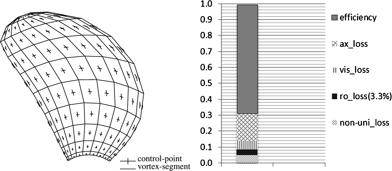
Potential theory propeller model (left, here a Vortex Lattice Method) and derived propeller specific losses (right). On the right the gap between actual propeller open water efficiency (here full scale assumed) and 1.0 is divided into different contributions. This gap assembles losses due to axial velocity increase (ax_loss), viscous effects (vis_loss), slipstream rotation (ro_loss) and non-uniformity (non-uni_loss), the latter resulting indirectly from the constant velocity increase assumed in the axial loss model.
A typical decomposition of losses is shown in Fig. 1. As the potential theory models usually do not capture the hub vortex contraction process along the boss cap, the corresponding added rotational losses are excluded in Fig. 1. A simple model for such supplementary losses will be introduced later in this section. Here we considered it reasonable to treat the rotational losses first up to a level valid for an infinite cylindrical and frictionless hub.
In Fig. 1 we assumed open water conditions for a propeller originally designed for in-behind operation and realized a typical thrust coefficient
The losses due to non-uniformity are filling the gap caused by the idealized treatment of axial and rotational losses. They are supposed to assemble mainly axial losses, the former not covered by the simple actuator model as it introduces a homogeneous added axial velocity
Compared to the open water situation, an increased and case-dependent non-uniformity loss level characterizes the in-behind case.
As the above model for the specific losses at a propeller of given geometry under given operational conditions is not yet sensitive to capture hub cap details, we also set up the generic rotational loss models in a decomposed manner. First we introduce a model valid for an infinite cylindrical and frictionless hub. Consequently any plane for the integration of rotational energy related to the circumferential mean value
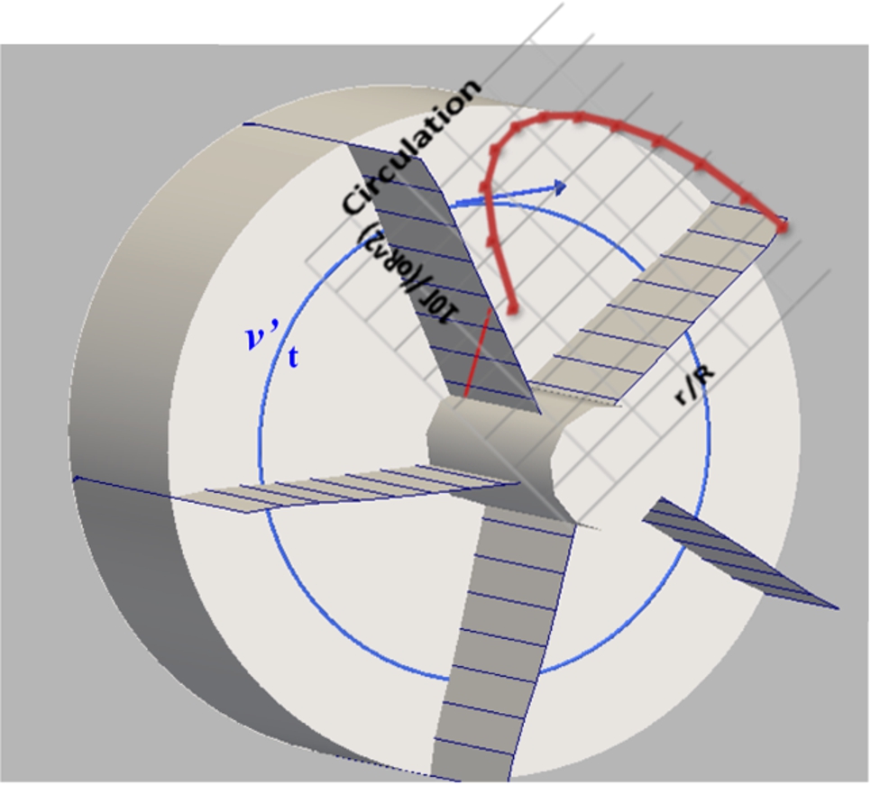
Model for the system of singularities and boundaries (infinite hub) ruling the circumferential mean value
When we gave an example for the ranking of losses with Fig. 1, it was also emphasized, that this ranking depends on the operational conditions and on the propeller geometry. In an early design stage it may be sufficient and intended to use global propeller performance data like thrust, torque and rate of revolutions, keeping in mind that in an initial stage it may introduce too much effort to work with detailed propeller geometries. Stepping over from a specific propeller to a generic substitute we proceeded as follows:
Using a normalized amplitude
Using a unique circulation shape function (
Considering a tube of length
Finally the flux of rotational energy across the propeller disc is needed to set up a power ratio. The energy flux through the disk would read
Consider there would be a device introduced in front of the propeller for nothing else but for the production of counter-swirl by redirecting the straight inflow. It would show a negative force
Losses due to rotation will tend to rise if one includes a model for the vortex tightening process occurring along the boss cap. The boss cap will experience a strong suction force while this process is supposed not to influence the axial force at the propeller blades. The confined vortex structure leaving the hub will lead to the low pressures acting on the boss cap. As a consequence the level of losses given in Fig. 1 might slightly change when this effect is built-in.
When the propeller hub vortex is taken into account, another clear benefit for producing pre-swirl compared to working on post-swirl can be assured apart from the strength arguments. If this vortex has developed already, useful energy may be hard to recover from such a confined and strong structure. On the other hand the hub vortex development can be suppressed conveniently by a pre-swirl device.
As outlined below, the thrust diminishing effect of this process may be estimated via two significant parameters. Introducing first the normalized hub circulation
This would mean that the suppression of the hub vortex contraction process would lead to 2% less thrust to be provided by the propeller blades, which – considering typical propeller efficiencies – would roughly correspond to a 3% saving in power!
Since 2D pressure fields have been assumed in the simplified hub vortex contraction model, a certain over-estimation on the suction force may be introduced here. At this stage of the hub vortex loss model and in view of a real stator hardware showing certain losses itself, it seems reasonable to work with an added 1.5% regain to cover savings due to hub vortex elimination.
Basic results on the relation of propeller and pre-swirl stator
The spread of the rotational loss level for a single propeller
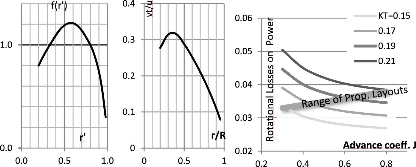
Propellers differ in size and are tailored to work at specific combinations of thrust, RPM and inflow speed. The question arises, whether a wide spread of rotational losses is to be expected. Assuming, that the shape of the circulation over radius
Figure 3 presents the propeller specific rotational loss level (excluding hub vortex contraction losses) as a function of J and
The profile of the tangential velocity in the slipstream – as displayed in the middle of Fig. 3 in normalized form – is an interim result. The curve’s shape is determined by the function
It is to be pointed out however, that the generic shape function
Comparing rotational loss levels for open water and in-behind
As the circulation developing on a given propeller is also depending on the inflow conditions, one should investigate the difference of rotational losses in open water and for the in-behind environment. Using a propeller designed for the in-behind case, we recognised a clear wake effect on the level of rotational losses.

The radial distributions of the normalized local axial flow
Figure 4 demonstrates that the circulation distribution (here valid for one blade and normalized by
As a conclusion one may emphasize to detail the distribution of load on the propeller and improve the preliminary results on rotational losses, which were based on a generic circulation.
The structure and the magnitude of the rotational losses have been addressed in the above. Next we need to consider an efficient process to prevent or convert them. If one decides in general for a pre-swirl device, at first sight it seems reasonable to aim at the profile of the tangential flow as predicted behind the propeller (see Fig. 3) and just reverse the direction. It was one demand in the GRIP project to derive realistic power gains for a stator implementation, i.e. account for ‘side-effects’ coming along with a physical pre-swirl stator installation.
To estimate the potential benefit of a pre-swirl device, we introduce first a stator/propeller interaction scenario valid for an ideal stator. In the first step, we keep also the propeller geometry unspecified. Fixing the two parameters that rule the rotational losses at the propeller, namely J and
Matching the profile of the propeller to 100% might not represent the optimum for a physical stator installation since there are always losses present in the swirl generation process. One may introduce
Similarly one can introduce with
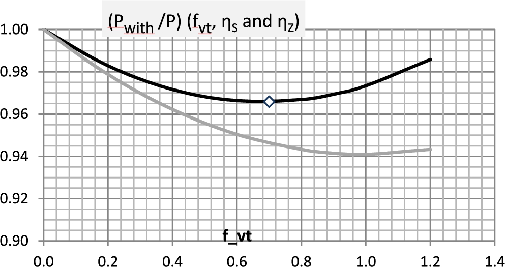
Introducing efficiencies (
This comparison results into the two curves as displayed in Fig. 5. The usage of the emphasized settings (
Stepping from the early assessment of the power reduction effect of a pre-swirl stator to the behaviour of a specific propeller it is reasonable to detail the distribution of the swirl
Though addressing here RPM and power at a specific propeller we still assume that the generic character of the stator remains. This generic device is given the ability to generate the specific
The change of the propeller operation with pre-swirl stator is illustrated in Fig. 6. The
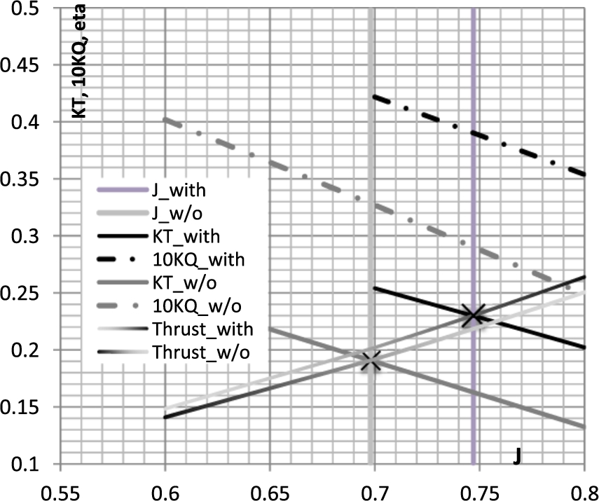
Typical shift of propeller operation point with and without pre-swirl stator. The curves labeled ‘Thrust_w/o’ and ‘Thrust_with’ identify the thrust requirement when thrust is normalized as
Linked to Fig. 6 the values for normalized thrust and power without and with stator can be taken from Table 1. Here we also give a comparison of the actual power savings and the predictions from the simple rotational loss model in case of full recovery (
Advance coefficient J, thrust coefficient KT, normalized absolute thrust and power without as well as with stator according to BEM analysis for a specific propeller case
Design targets
One has to account for the inflow to the stator as experienced behind the hull when stepping from the idealized stator to a real device (as sketched in Fig. 7). The stator sketched in Fig. 7 is however hardly suitable for a single propeller case. Behind a hull the single propeller will usually work in an inclined flow. For the layout of a pre-swirl device the inclined flow situation introduces an asymmetry. The propeller already partly receives properly directed incoming swirl (for a right turning propeller on Stb) and partly experiences just the opposite (on Port). Depending on the angle of inclination it seems natural to concentrate stator fins on Port rather than to distribute them uniquely.

A ‘real’ stator device showing cambered sections and a reasonable outline (here as a 5-bladed version with symmetrical arrangement of fins).
If the flow information valid at the stator plane was obtained via a ‘bare hull’ RANSE analysis, this flow should be corrected for propeller-induced velocities. The former findings based on the generic PSS model and depending on the efficiency factor settings (
Thus the
The analogy of circulation and swirl production leads to the comparison given in Fig. 8. On the left of this figure the circulations on stator fin and propeller blade are similar in magnitude and assumed reversed in sign. The contributions to the mean swirl by one fin and one blade are thus the same in magnitude but they cancel each other due to the opposite directions. As we assume a 3 bladed stator and a 4 bladed propeller in Fig. 8, the overall stator-‘effort’ for swirl production reads 75% of the total swirl shed by the propeller. This corresponds to the realization of

If
Most of the considerations given above assume uniformity in tangential direction for the propeller inflow and for the propeller loading, i.e. the propeller blade position
There might be additional recovery prospects, if these ideal propeller inflow conditions expressed with the 2nd design target are realized. It appears that additional research is necessary to forecast such added gains depending on the actual constellation.
In the FP7 EU project GRIP the task was given to design an energy saving device (ESD) for a full scale validation ship. The test case ship available in this project was a 182 m Bulk Carrier built by the partner Uljanik Shipyard. HSVA designed an ESD in form of a pre-swirl stator for this ship. This was also the device finally selected in the project and installed on the Uljanik bulker. The trials were very successful (see reference [3]) and showed a power saving of 6.8% due to the pre-swirl stator, which is higher than the numerical (RANS) predictions performed before the trial (see reference [7]). On the basis of HSVA’s viscous calculations we will below investigate, what the simple estimation models introduced above would predict if supported by some interim results from the RANS analysis.
The code that is mainly used by HSVA, FreSCo+, solves the incompressible, unsteady Navier-Stokes-equations (RANSE). For the Uljanik bulker case it was applied for full scale conditions. The propulsion situation was modelled via a RANS-BEM coupling, internally labelled as the ‘RANS-QCM’ coupling. Via this approach, one obtains the wake components at the propeller plane including the effects of streamline contraction, the so called ‘effective’ wake. As the full scale analysis was done at HSVA under propeller operation with as well as without stator, there were two different profiles available for the effective tangential wake component, which is giving the level of pre-swirl arriving at the propeller. The contour plots for these tangential components (
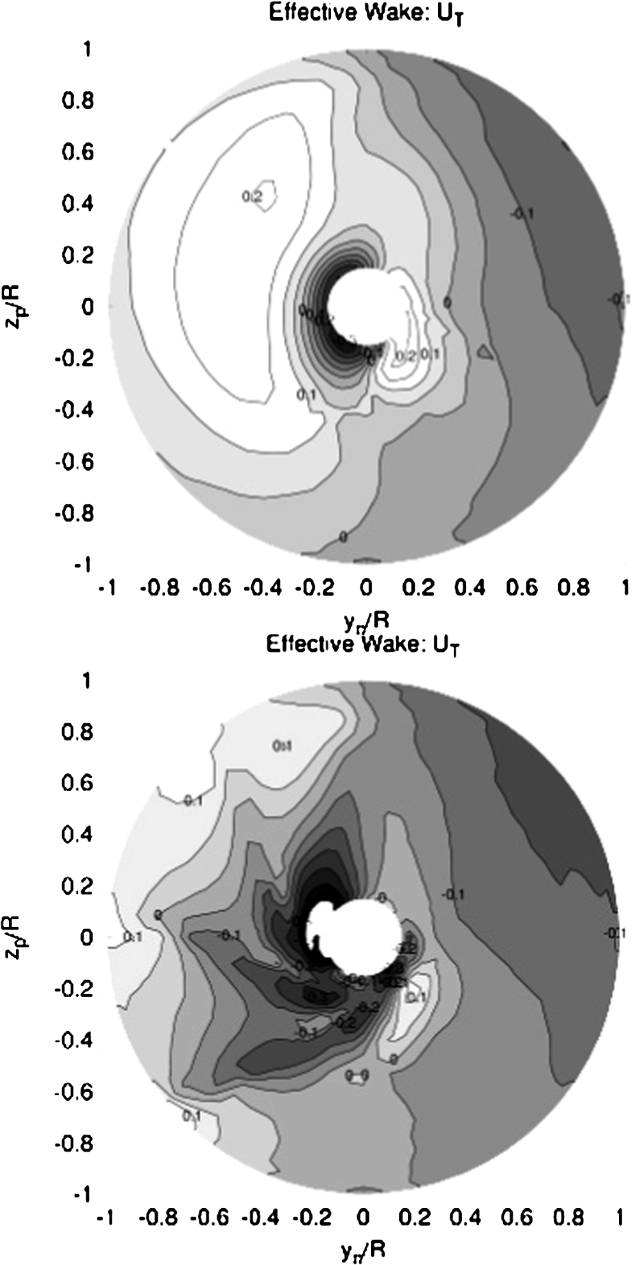
‘Uljanik’ case: effective tangential wake w/o stator (top) and effective tangential wake with mounted pre-swirl stator (bottom) according to full scale hull flow analysis using FreSCo+. The tangential component is normalized by ship speed.

‘Uljanik’ case: Difference of effective tangential wakes with and w/o pre-swirl stator (based on ship speed).
From the bottom plot of Fig. 9 (giving the contours for the tangential component with mounted stator) one may identify a reasonably rotational symmetric pattern, which has been established by the pre-swirl device. To link Fig. 9 to the simple models formerly described in this paper, we subtracted the top plot from the bottom plot. The result is shown in Fig. 10, which illustrates clearly, that the highest pre-swirl effort was done on Port (where indeed all three stator fins were positioned in a further upstream plane). As the models presented above are based on the circumferential means of the tangential flow, such mean values were derived from the pattern of Fig. 10 and are presented in Fig. 11.
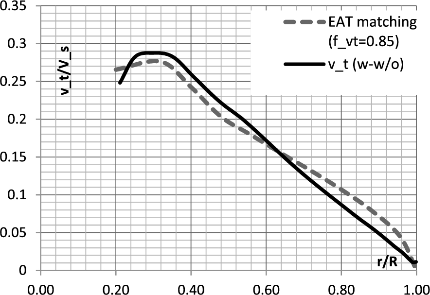
Actual pre-swirl profile (v_t(w-w/o)) and ‘matching’ profile (dashed), the latter from the simple estimation model described in this paper with effort parameter set to f_vt = 0.85.
This figure also includes a ‘matching’ distribution, which was obtained from the generic circulation of the simple model. The matching curve involves the actual values of
With inclined flow as present for in-behind conditions one is in a different situation: the initial propeller inflow can be regarded as circumferential non-uniform swirl and – with the help of the PSS – an overall more uniform swirl is lastly provided to the propeller. For the propeller, experiencing not only swirl but also an enhanced uniformity, one might even consider that 1.0 doesn’t represent the upper limit for the parameter
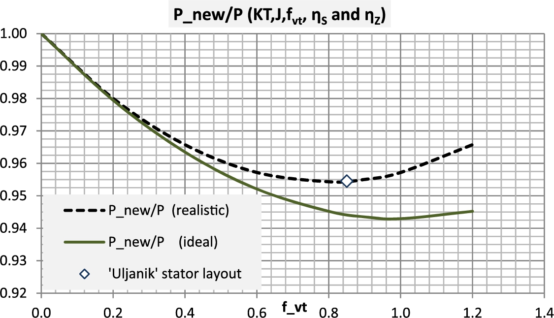
Using the simple estimation model to locate the ‘Uljanik’ pre-swirl stator layout in the general effort(f_vt)/payback(P_new)-diagram.
If we set
In the above we presented simple methods to quantify the rotational losses of a ‘stand alone’ propeller in general. The plural ‘losses’ is justified since for convenience we divided the process into two parts. Part one excludes the further contraction of the shed vortex system after passing the propeller blades while part two treats the added loss effect due to the hub vortex contraction.
Introducing in the radial direction a generic distribution for the blade load, the losses caused by these two processes are deduced from the global parameters
It was further outlined how estimations on power reduction valid for a mounted pre-swirl stator can be deduced from the idealized treatment of rotational losses. To link a theoretically optimum pre-swirl stator to a realistic stator design a ‘reduced effort’ philosophy was introduced. Discussing on the RPM drop under pre-swirl presence, it was considered unavoidable to reference the actual propeller geometry at this stage.
Lastly we leave the theoretical assumptions on the flow environment of propeller and stator gradually and formulate design targets for real stator hardware. An in-house Boundary Element Method has been used at the Hamburg Ship Model Basin to link design targets and stator geometry. It guarantees a quick investigation of various stator alternatives. In viscous flow computations involving the hull, the stator and the propeller the final fin design should be proven and confirmed (and probably altered accordingly). This step was very decisive for the Uljanik test case, since the RANS analysis enables the final selection of the optimum fin design (see reference [7]).
For the Uljanik tests case (intensively studied in the GRIP project up to full scale trials with mounted pre-swirl stator) we demonstrated how the RANS calculations and trial results fit to the simple model for the early assessment of power saving potentials.
As a conclusion it may be stated that the simple estimation model proved to deliver very reasonable results. Due to the typically inclined flow situation of a propeller behind a mono hull the simple modelling may require adjustments to cover additional stator benefits arising from an improved homogeneity of the flow to the propeller. Also the quantification of the hub vortex contraction losses is complex and has not been completed yet (especially one should try a RANS modelling with cavitation involved). Currently it appears, that the globally derived 1.5% power savings for a ‘counter hub vortex’ device may be too conservative.
Footnotes
Acknowledgement
The authors really acknowledge the supports obtained via the European FP 7 project GRIP. This project allowed for both, financial funding and exchange and cooperation with other participants. These aspects appeared to be essential for the realization of the above study on pre-swirl devices.