
Abstract
This paper proposes a numerical scheme for the fast calculation of an efficiency map in Permanent Magnet Synchronous Motors (PMSMs). The efficiency map is the main performance feature required to design traction motors for electric vehicles. To obtain the efficiency map, iron losses must be calculated across wide speed and current ranges. The iron losses can be estimated from magnetic flux waveforms, which require a huge amount of non-linear time-stepping finite element analysis (FEA) solutions. In this work, the flux waveform estimation scheme is proposed aiming to reduce the number of required FEA solutions. The proposed scheme removes the redundant FEA calculation based on the fact that the time variation of the field at one position is matched with the space variation of the field at one time step in PMSMs. To verify the effectiveness of the proposed scheme, not only the flux waveform, but also the iron losses and efficiency map of a PMSM is calculated using both conventional and proposed approaches. The comparison results show that the computation time to build a single efficiency map can be reduced from 8.8 hour down to 1.1 hour within around 5% errors.
Keywords
Introduction
Permanent magnet synchronous motor (PMSM) is one of the most popular choices for the traction motor of electrified vehicles due to its high efficiency and power density. One of the recent research trends for automotive traction motors is the design for improved real-world operating efficiency under vehicle driving schedules [1, 2, 3, 4, 5, 6, 7]. In [1], the PMSM circuit topology was proposed for the high efficiency in the low speed and low torque operating region representing urban driving. In [2, 3, 4], the PMSM geometric parameters were designed to improve efficiency at frequent operating speed and torque ranges for given driving cycles. The energy consumption of PMSMs over the standard vehicle driving cycle were compared with that of a switched reluctance motors in [5]. In [6], the PMSM, induction motor, and surface mounted permanent magnet motor are compared in terms of energy consumption over the European driving cycle. The motor design studies based on vehicle driving schedule [1, 2, 3, 4, 5, 6] require accurate and fast calculations of the efficiency map over the wide operating speed and torque ranges. In [7], the size of electric motor is designed in hybrid electric vehicles involving driving cycle. In addition, various studies have been performed to estimate and improve the motor efficiency [8, 9, 10]. In [8], an in-wheel surface mounted PMSM is optimized to achieve high efficiency and low weight. The efficiency of a concentrated winding synchronous reluctance motor was estimated and validated in [9]. In [10], the relation between efficiency and temperature rise was evaluated depending on magnetic properties
The procedure to estimate the efficiency map of PMSMs is demonstrated in Fig. 1. The efficiency map can be predicted from the combination of the mechanical power
Procedure to estimate efficiency map of permanent magnet synchronous motors.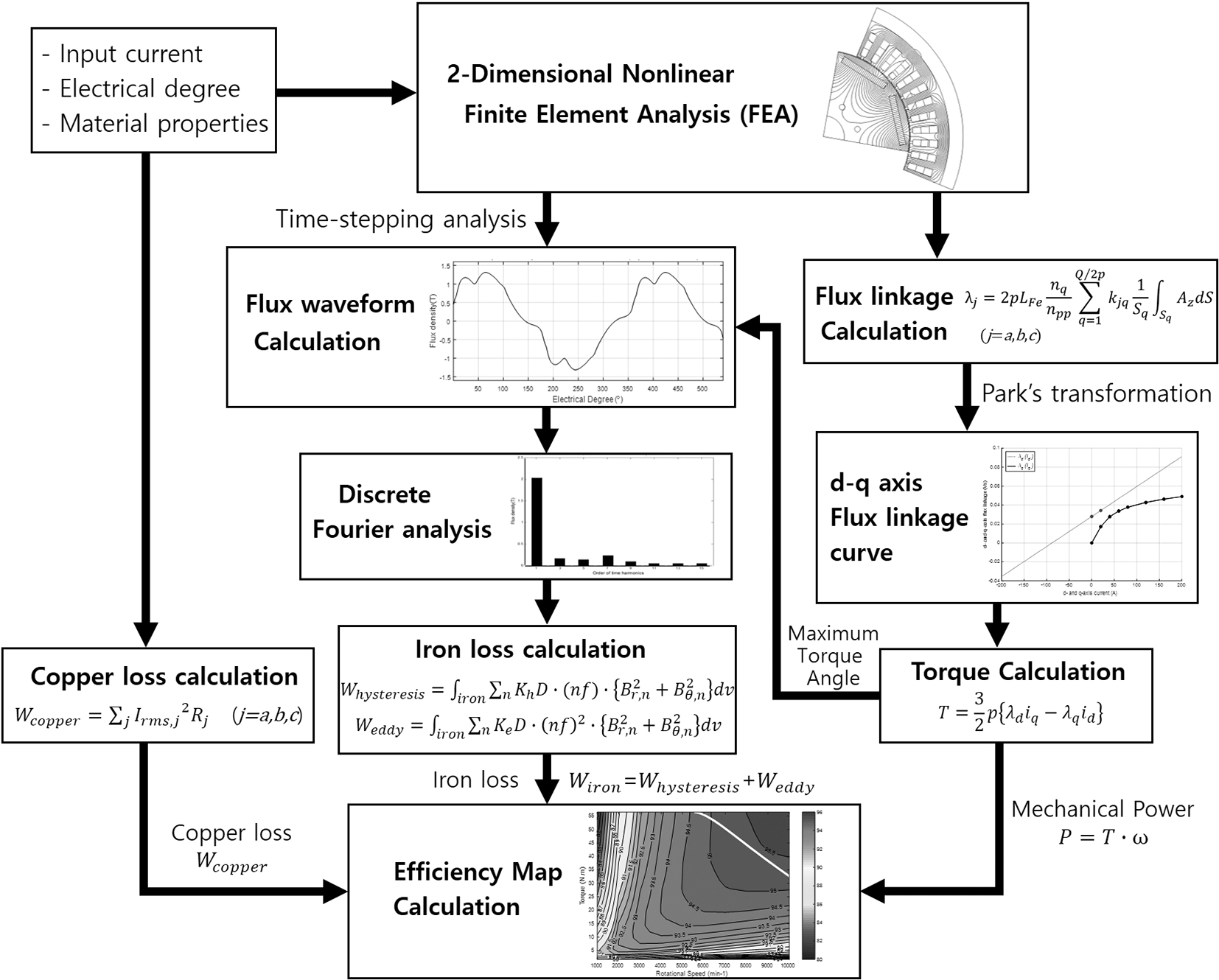
In the efficiency map prediction process, the iron loss estimation is predominantly time-consuming task because it requires the computation of time-varying magnetic flux waveform during the motor rotation. For the flux waveform calculation, the analytical model based on the equivalent circuit analysis was proposed in [13, 14]. Although the analytical approach is fast and simple, it has a limitation that the detailed motor geometry is ignored in the analysis result, and thus unsuitable for geometry design studies. The FEA is a more popular approach that can calculate the flux waveform reflecting the detailed motor geometry. As shown in [15, 16, 17, 18], the nonlinear time-stepping FEA approach has been used for the flux waveform calculation of PMSMs. Here, the time-stepping means that the FEA is repeated at each time step corresponding to discrete rotor angles, and the nonlinearity needs to be considered because the PMSMs mostly operate under the magnetic field saturation.
When using the nonlinear time-stepping FEA for the flux waveform calculation, the efficiency map prediction process takes a considerable amount of computational cost due to its nonlinearity and wide speed and torque ranges. Thus, it precludes the motor designer from optimizing the geometry and other input parameters of PMSMs requiring the repetitive calculation of efficiency maps. If assuming that the optimization iteration requires 50 number of function calls for calculating efficiency map composed of 200 data points (20 torques points for each 10 speed point), it takes more than 15 days to obtain optimization result in our calculation. Due to the huge amount of computational cost, the design process in [1, 2, 3, 4, 5, 6] have been limited to the efficiency map comparison of few design cases.
Accordingly, this paper proposes an efficient flux waveform estimation scheme based on FEA aiming the fast calculation of the PMSM efficiency map. In the proposed scheme, the computational cost is significantly reduced, still based on the FEA result. The reduction of computational cost will enable the motor designer to optimize the PMSM for improved real-world operating efficiency under vehicle driving schedules. The proposed scheme removes the redundancy in the FEA solutions using the fact that the time variation of the magnetic field is matched with the space variation of the magnetic field in PMSMs. In other words, the magnetic flux densities at one position in several time steps can be replaced with flux densities at appropriate locations in one time step. In this way, the number of time step for the nonlinear time-stepping FEA can be significantly reduced with acceptable loss of the analysis accuracy. The proposed scheme is limited to the calculation of the stator flux waveform under the steady-state operation. In the viewpoint of PMSM efficiency map calculation, this limitation is acceptable because the PMSM efficiency map is generally calculated at steady-state operation, and the rotor iron loss in PMSM is much smaller than the stator iron loss due to the synchronization of the rotor speed and stator magnetic field.
To verify the effectiveness of the proposed scheme, not only the flux waveform, but also iron losses and efficiency map of a PMSM are calculated using both the proposed scheme and the conventional time-stepping approach. In the verification process, the PMSM specification in [15] is utilized. For the estimation of iron losses from the flux waveforms, the harmonic iron loss calculation approach using the DFT [12] is applied in this work. Note that the other iron loss calculation method such as the modified Steinmetz approach [19] or direct calculation from the flux waveform [20] can be also combined with the proposed flux waveform estimation scheme.
The outline of this paper is as follows: in Section 2, the concept of the proposed waveform estimation scheme is explained. The effectiveness of the proposed scheme is validated in Section 3 by comparing the flux waveforms of a PMSM obtained from the proposed and conventional approaches. In addition, the iron loss and efficiency map using the proposed approach is compared with them using the conventional approach. Finally, Section 4 summarizes the paper’s conclusions.
This section explains the concept of proposed scheme for the fast calculation of magnetic flux density waveform. The flux waveform is the requisite data for the motor iron loss estimation. Here, the conventional approach based on nonlinear time-stepping FEA is firstly explained. Then, the concept of the proposed scheme is explained through two cases. In the first case, the concept is explained in the ideal PMSM in which the stator has a simple tube shape without tooth. In the second case, the proposed concept is expanded for the application to more realistic PMSM including the stator teeth for winding.
Conventional approach using nonlinear time-stepping FEA
The conventional approach finds the time-varying magnetic flux density waveform
where
where
The conventional approach solves Eq. (1) at
The proposed scheme enables us to reduce the number of nonlinear FEA solutions required to build the flux waveform. Here, the proposed scheme is first explained in the ideal PMSM having the tube shape stator without teeth for winding as shown in Fig. 2. Figure 2a and b compared the conventional and proposed approach needed for flux waveform calculation. The conventional approach solves the nonlinear Maxwell’s Eq. (1) at each time step. As shown in Fig. 2a, the magnetic flux density at the position A for three time steps (
Comparison of conventional and proposed approach in ideal PMSM; (a) Conventional approach. For calculating magnetic flux at three time steps, nonlinear FEA should be performed three times. (b) Proposed method. One nonlinear FEA result provide flux density at three time steps. (c) Flux density waveform from conventional and proposed approach is exactly matched in the ideal case.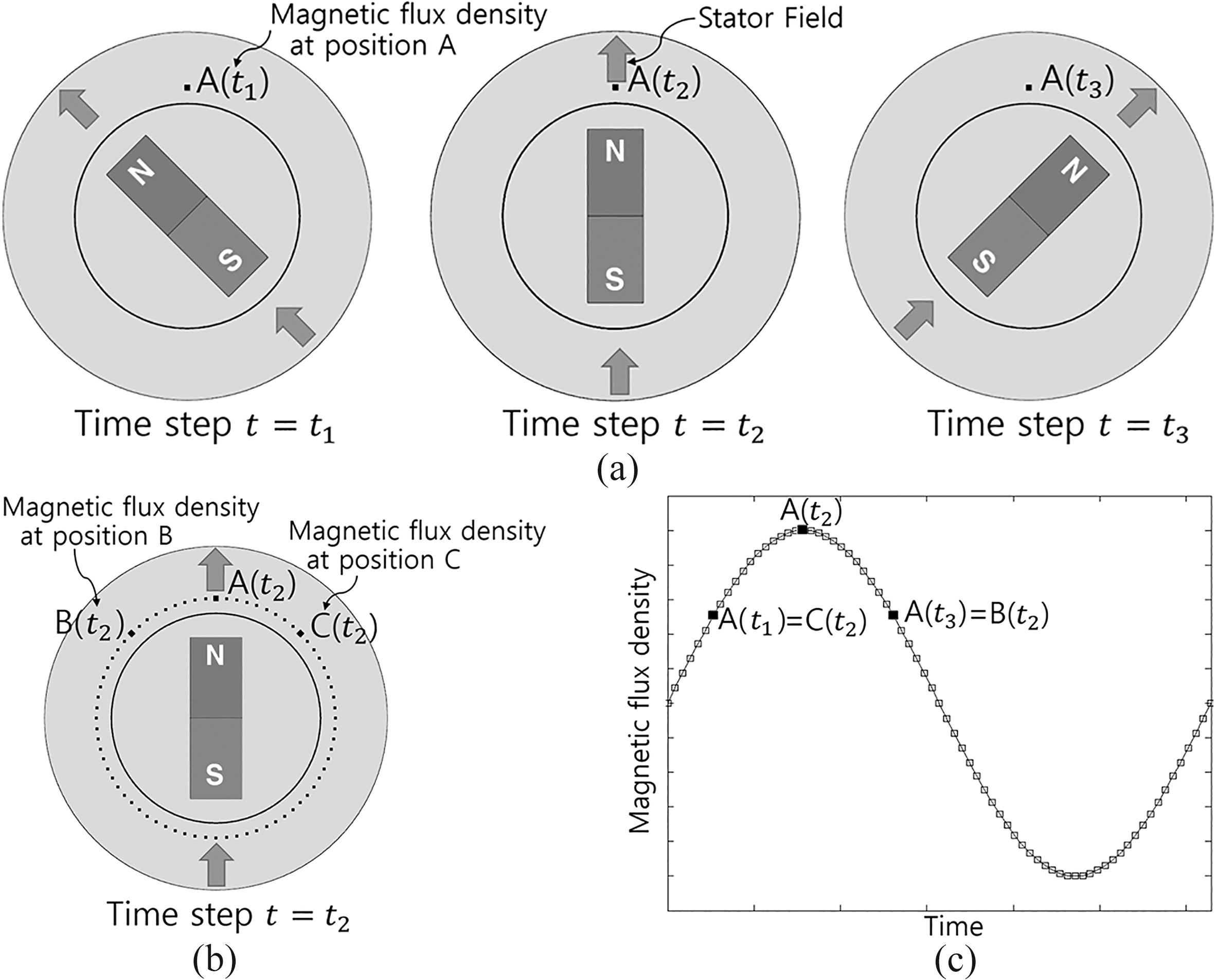
A PMSM with ideal tube shape stator.
The proposed approach is based on the fact that the time variation of the magnetic field at one position is identical with the space variation of the field at one time step. In other words, the magnetic flux density at the position A at three time steps is exactly matched with the flux density of appropriate locations at one time step; the magnetic flux density A (
To clarify the proposed concept, it is applied to the actual PMSM with ideal tube shape stator. Figure 3 shows the applied ideal PMSM. The 3-phase windings are sinusoidally distributed at 48 locations, and the rotor is consisted only with a permanent magnet. The target point for the magnetic flux waveform calculation is marked as red in the figure. For the flux calculation at 180 electrical degrees, the conventional approach finds 60 FEA solutions (i.e. flux calculation for every 3 electrical degrees). However, the proposed approach utilizes only one FEA solutions for the same calculation. Instead the flux at 60 points marked as blue in the figure, is utilized for the calculation. Figure 4 shows the flux waveform comparison results. As expected, the flux waveform obtained using the proposed approach is well matched with the waveform using the conventional approach. The discrepancy in y-directional flux around 120 electrical degrees might be due to the imperfect windings (i.e. sinusoidal distribution is approximated into windings at 48 locations). Note again that the propose approach using 1 FEA solution can save a huge computational cost compared to the conventional approach using 60 FEA solutions.
Comparison of magnetic flux waveform obtained using the conventional approach (60 time steps) and the proposed approach (1 time step): (a) 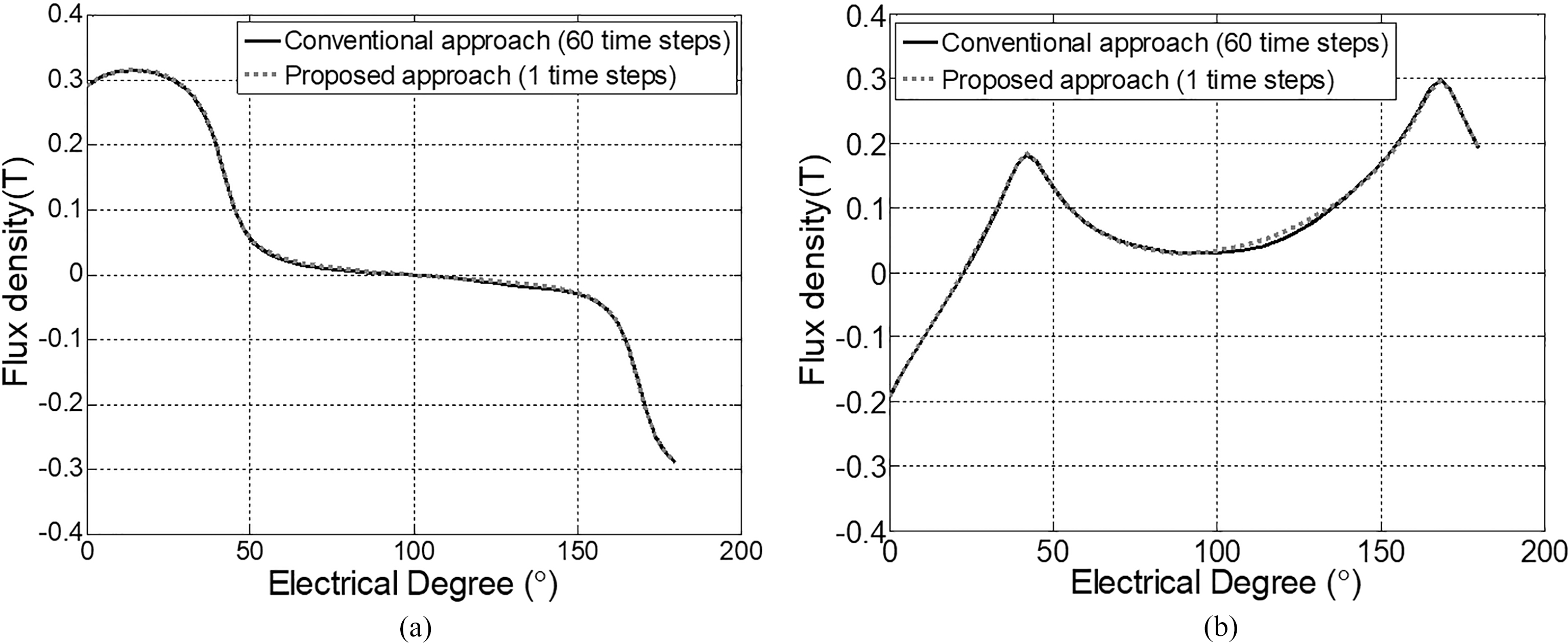
The proposed flux waveform calculation method is expanded for the realistic PMSM including stator teeth as shown in Fig. 5. Figure 5a presents the stator field location (arrow) and rotor position at 4 time steps (
Comparison of conventional and proposed approach in realistic PMSM including stator tooth; (a) Conventional approach. For calculating magnetic flux at four time steps, nonlinear FEA should be performed four times. (b) Proposed method. Combination of two nonlinear FEA result provide flux density at four time steps. (c) Flux density waveform of conventional and proposed approach is exactly matched.
The basic concept of the proposed approach for the realistic PMSM is same with the concept for the ideal PMSM explained in the above. The idea is again based on the fact that the time-varying magnetic field at the specific position is matched with the space-varying magnetic field at the specific time. The difference between ideal and realistic PMSM is the existence of the stator teeth for windings. Due to the stator teeth, the air region exists between the stator iron teeth, where the magnetic field cannot be calculated to replace the field at appropriate time steps. Thus, one FEA solution is not enough to build the flux waveform unlike the ideal case. To resolve this problem, FEA solutions at two time steps can be combined as shown in Fig. 5b. Then, the flux density of appropriate locations at two time steps can replace the flux density at various time steps; the magnetic flux density A (
The limitation of the proposed approach can be summarized as follows. The proposed approach might not be appropriate when the stator edge effect is significant or the stator field distribution is severely distorted. In this case, the discrepancy of the flux waveform obtained using the proposed and conventional approaches might be unacceptable. At the edge of the stator teeth, the match of flux density in space and time variation might be broken due to the geometry effect. The discrepancy due to the edge effect of stator teeth becomes significant when the tooth width is narrow. This problem can be relieved by increasing the number of time step into more than two. In addition, the distorted stator winding field distribution in the PMSM can cause the discrepancy in flux waveform calculation results. As explained, the proposed scheme is based on the matching of the magnetic field in the space and time variation. To hold this matching, the magnetic field generated by stator winding current should rotate while maintaining the field distribution during the operation. If the winding distribution and input current is not perfectly sinusoidal, the field distribution is not maintained constant during the rotation. The distortion of the magnetic field distribution breaks the matching of flux density in space and time variation, which might result in the discrepancy in the flux waveform.
This section verifies the proposed scheme through the flux waveform calculation in a PMSM presented in [15]. First, the specification and configuration of the PMSM used for the verification is summarized. Next, the magnetic flux waveform at five rotor positions are calculated in two cases: (1) 30 time step conventional approach, (2) 3 time step proposed approach. The calculated flux waveforms are compared to validate the effectiveness of the proposed approach. Then, the iron loss and efficiency map calculation results are compared in two cases (i.e. the proposed scheme with 3 time steps, and conventional scheme with 30 time steps).
Specification of PMSM used for validation
Specification of PMSM used for validation
Configuration of PMSM and positions for flux waveform calculation used for the verification.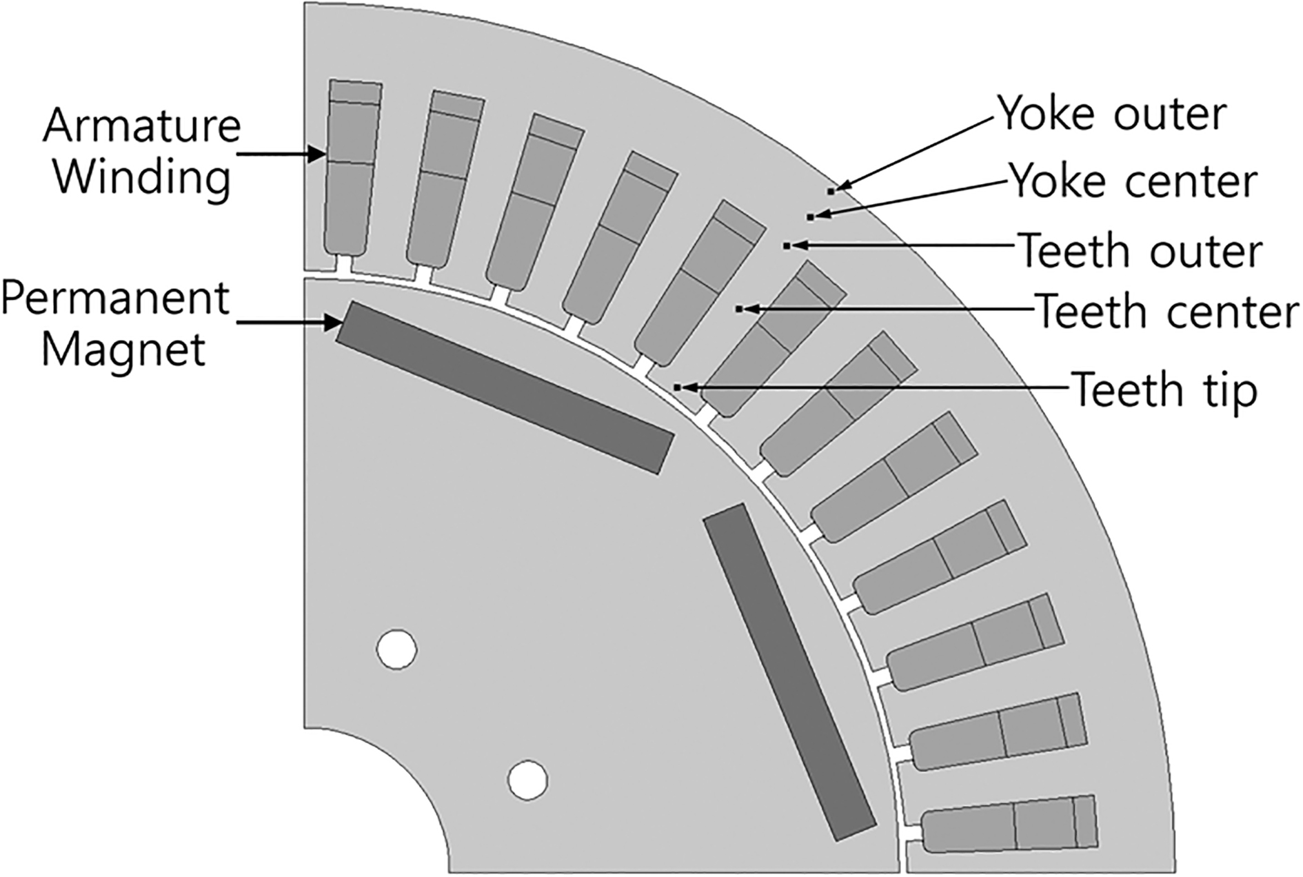
The specification and configuration of a PMSM used for the verification is identical with a PMSM presented in [15]. Figure 6 shows the configuration of PMSM, and the specification of the PMSM is summarized in Table 1. The 8 pole interior permanent magnet type PMSM with distributed windings are chosen for the verification of the proposed calculation scheme. Here, the saturation of the steel core is implemented, but the demagnetization of permanent magnet is ignored. The high order harmonic in the three-phase input current is ignored, and the only fundamental harmonic waveform is applied as the input current. For the verification of the proposed scheme, the magnetic flux waveform at five stator locations shown in Fig. 6 is investigated. Three locations in teeth and two locations in yoke are selected as identical with the locations used for the iron loss calculation in [15].
Positions where the magnetic flux densities are calculated for waveform calculation; (a) Conventional method using 30 or 3 time step solutions. The data at 5 locations are used to build the flux waveform for each location, (b) Proposed method using 3 time step solutions. The magnetic flux density at 6 points connected by dashed lines are used to build flux density for each location.
Comparison of radial component of magnetic flux waveform 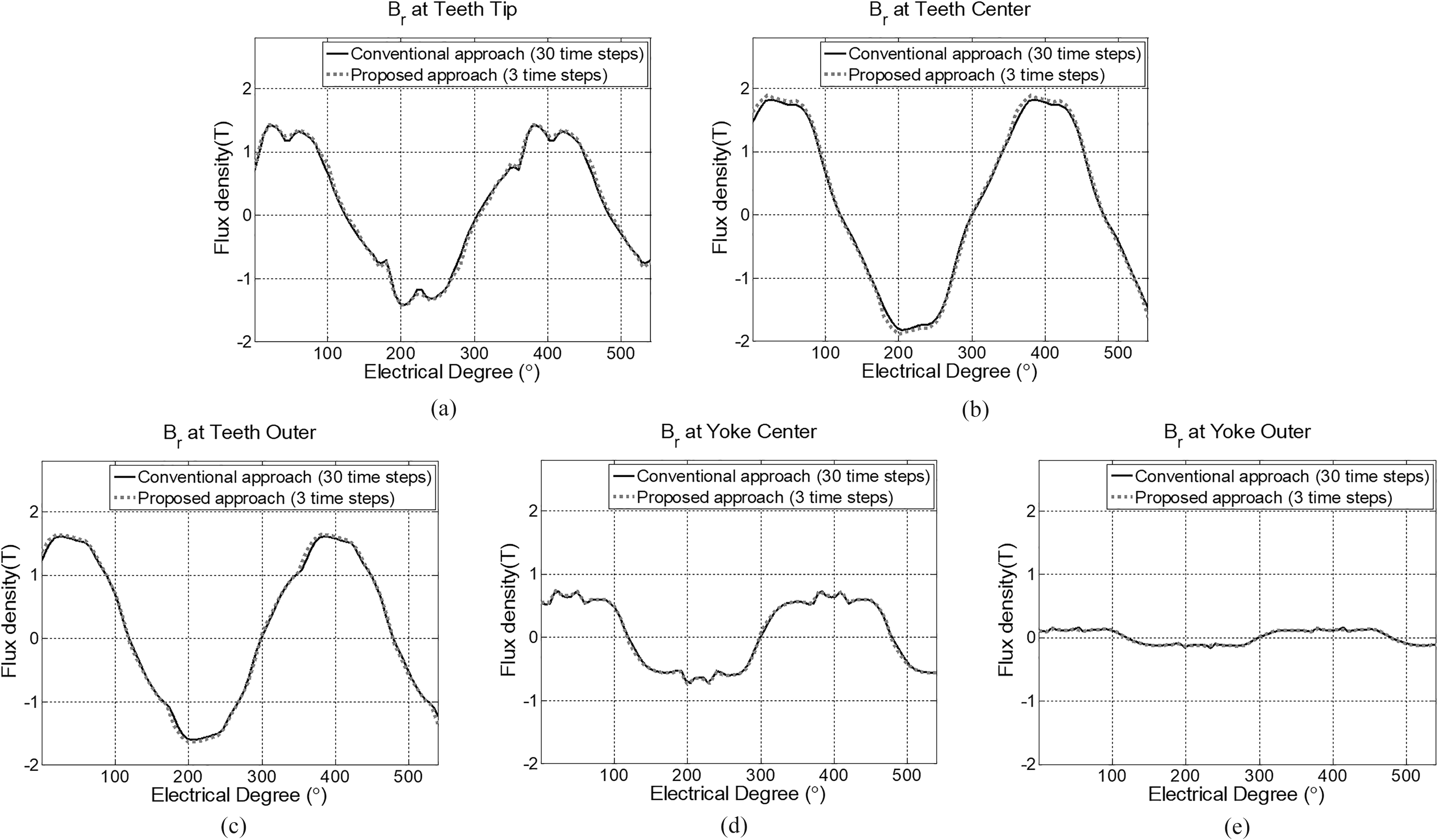
Comparison of peripheral component of magnetic flux waveform 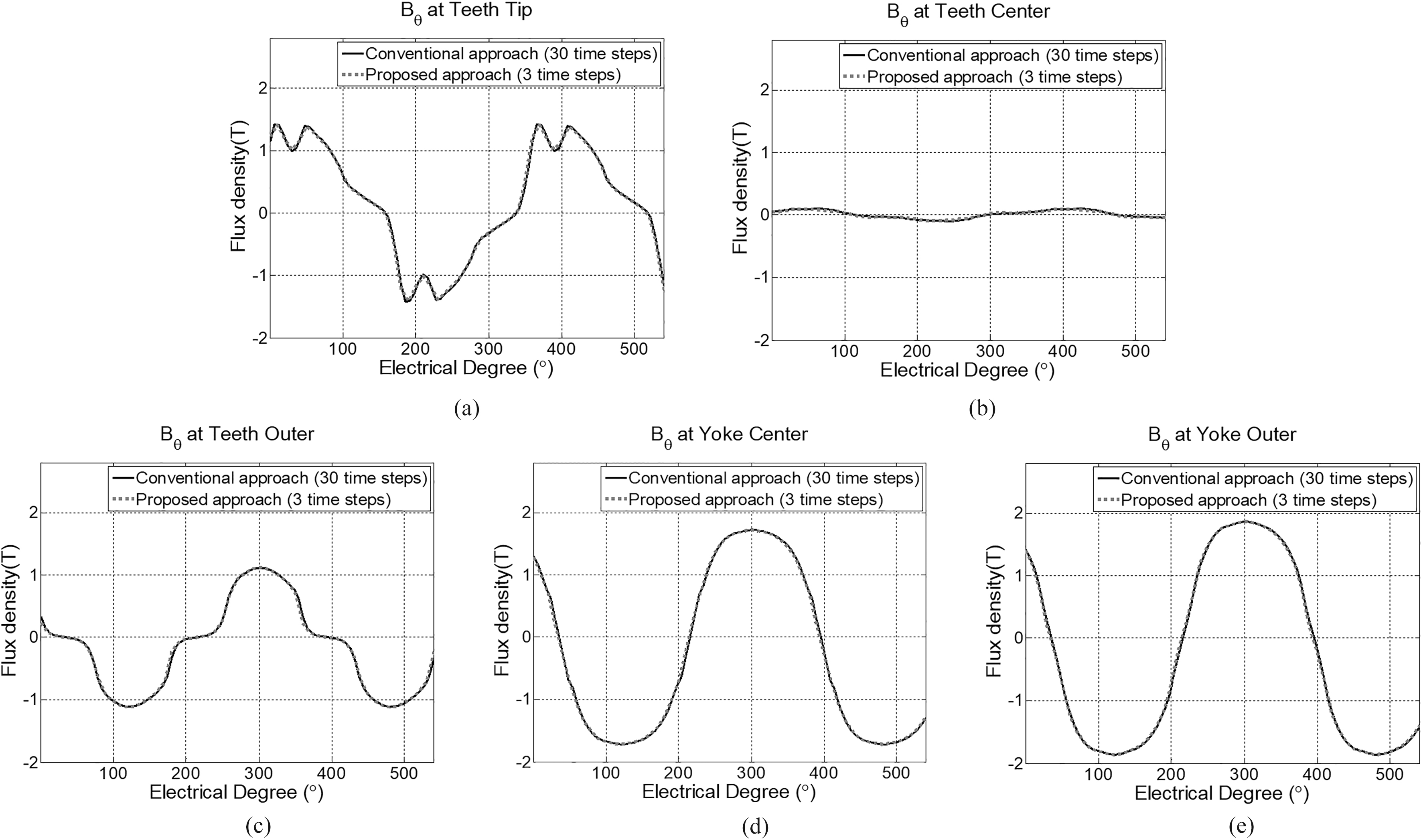
The nonlinear two-dimensional (2-D) FEA is carried out to calculate the magnetic flux density. Thanks to the periodicity of the magnetic flux density, the 1/4 finite element model of the PMSM is used for the field analysis with the periodic boundary condition [11]. The air region outside the stator is included to represent the leakage magnetic flux outside the motor. The second order triangular finite element is applied for the analysis. The number of finite elements is about 14,000 elements (slightly different depending on the rotor angles), and the degree of freedom is about 60,000.
The magnetic flux waveform at aforementioned five locations are calculated using both the conventional and proposed method. As explained, the conventional approach calculates the flux waveform using the nonlinear time-stepping FEA. Here, the flux waveform of two cases are compared: (1) the conventional approach with 30 time step FEA solutions, (2) the proposed approach with 3 time step FEA solutions.
The analysis points used for conventional and proposed approaches are presented in Fig. 7a and b. Due to the symmetry of the flux waveform, the electrical degree required to build the flux waveform ranges the half of the one period (0
The flux waveform calculation results of two cases are plotted together in Figs 8 and 9. Here, the waveforms are calculated when the input current is 100 A. For the iron loss calculation (i.e. next step to build efficiency map), the magnetic flux waveform is decomposed into the radial and peripheral compents. The radial components of the flux waveform for three cases are compared in Fig. 8, and the peripheral components are compared in Fig. 9. The flux waveform of the 3 time step proposed scheme are almost exactly matched with that of the 30 time step conventional approach for both radial and peripheral components. This comparison validates that the proposed scheme can provide accurate flux waveform with much fewer FEA solutions.
Comparison of iron losses
The iron losses calculated using the conventional approaches are compared with the losses using the proposed approach. Figure 10 compared the harmonic components of the iron losses (i.e. sum of the hysteresis and eddy current losses) in two cases: (1) 30 time step conventional approach, (3) 3 time step proposed approach. As expected, the iron loss components of the 3 time step proposed approach is well matched with the result of the 30 time step conventional approach.
Harmonic component comparison of iron losses at 2000 rpm when the input current is 100 A. The result of 30 time step conventional approach is compared with the result using 3 time step conventional and proposed approaches.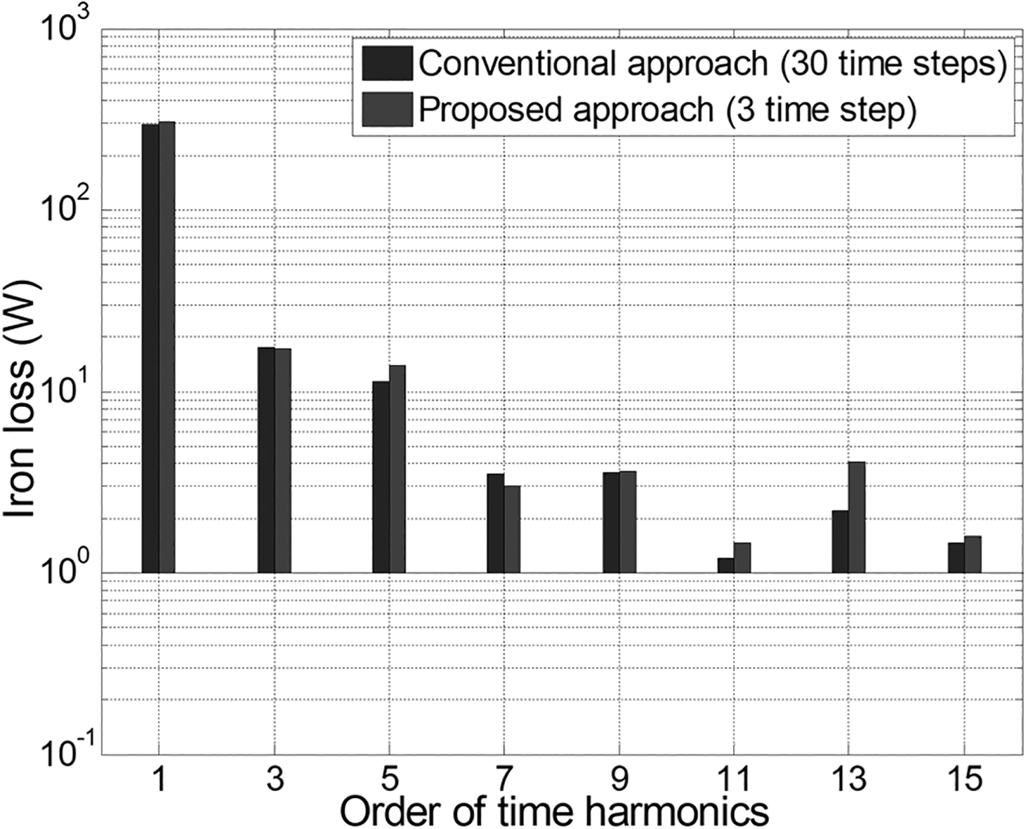
Plot of relative error (%) map of iron losses in the case of proposed approach with 3 time step. The iron loss of 30 time step conventional approach is regarded as the true value. The losses in 200 data points are calculated; the current ranges from 10 A to 200 A at intervals of 10 A. The speed ranges from 1000 RPM to 10000 RPM at intervals of 1000 RPM.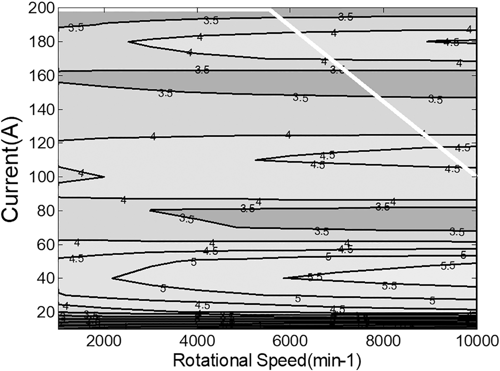
Efficiency map comparison to validate the effectiveness of the proposed flux waveform calculation approach. (a) Conventional approach with 30 time steps (b) Proposed approach with 3 time steps.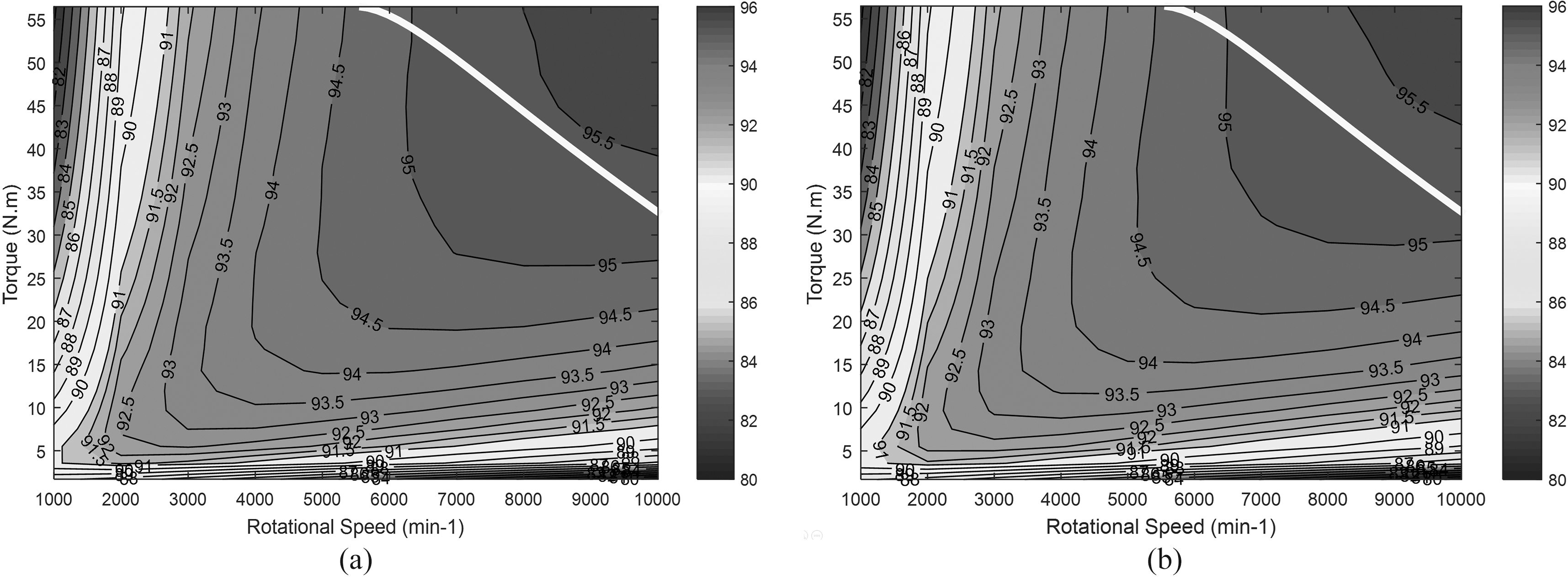
Next, the relative error
where
Figure 12 presents the calculated motor efficiency map. To build the efficiency map, 200 data points are utilized (20 torque points for each 10 speed point). Figure 12a is the efficiency map when the iron losses are calculated using the 30 time step conventional approach, and Fig. 12b is the map when the proposed schemes with 3 time steps are applied. As can be noticed in Fig. 12, the efficiency map of the proposed approach is well matched with the map of 30 time step conventional approach.
Table 2 compares the accuracy and computational costs to build an efficiency map in three cases. The computation is performed on a quad core workstation with a 3.0 GHZ processor and 8 GB of RAM. As explained, the 30 time step conventional approach finds iron losses by performing the nonlinear FEA 30 times, and consequently requires huge amount of computational cost. In contrast, the 3 time step proposed scheme reduces the required number of FEA solutions for iron loss calculation with acceptable errors (maximum 5.78%, average 3.86%).
Comparison of computation cost and accuracy to build an efficiency map in three cases
Comparison of computation cost and accuracy to build an efficiency map in three cases
The computation cost for the torque calculation is modest compared to the cost for iron loss calculation. Thus, the advantage of the cost reduction for iron loss calculation still holds for the efficiency map calculation. When applying the proposed scheme, the computation cost to build an efficiency map is reduced from 8.8 hour to 1.1 hour (87.5% reduction). It should be noted again that the huge reduction of the computational cost enables us to perform the repetitive calculation of motor efficiency map. Assuming that the design optimization requires 50 number of function calls to calculate efficiency maps, the conventional approach takes 18.2 days to complete the optimization process, but the proposed approach might provide a similar result within 2 days.
The numerical method to calculate the flux waveform of PMSMs is proposed in this work. The proposed approach can be effectively used for the motor designers who need the repetitive calculation of the efficiency map. To calculate the efficiency map, the conventional approach based on the nonlinear time-stepping FEA requires the huge amount of computation costs due to the estimation for wide speed and torque ranges. The proposed approach enables us to reduce the required number of FEA solutions for flux waveform calculation. This reduction is possible because the time periodicity of the magnetic flux density is matched with the space periodicity in PMSMs. The proposed approach is applied for the flux waveform calculation of 8 pole interior PMSM presented in [15]. The flux waveform obtained using the proposed approach is compared with the waveform using the conventional time-stepping approach, and the effectiveness of the propose approach is validated. The computation time to build a single efficiency map can be reduced from 8.8 hours (30 time step conventional approach) to 1.1 hours (3 time step proposed approach) with acceptable loss of accuracy (3
Footnotes
Acknowledgments
This research was supported by Basic Science Research Program through the National Research Foundation of Korea (NRF) funded by the Ministry of Education (NRF-2016R1D1A1B03931138).