
Abstract
Due to the vulnerability of power transformer windings to overcurrent impact during operation, significant electromagnetic forces are generated, posing potential hazards of failure. Therefore, it is crucial to conduct an analysis of the electromagnetic forces under overcurrent conditions. In this study, a three-phase power transformer model is established, with specific attention given to the refinement of winding modeling. Utilizing Maxwell software, the simulation and analysis of the leakage field of transformer windings, axial distribution of electromagnetic forces, and their transient processes over time are performed under short-circuit currents and magnetizing inrush currents during no-load closure. The simulation results reveal that both types of overcurrent result in axial electromagnetic forces on the windings that are larger at the ends and smaller in the middle. However, for magnetizing inrush currents, higher harmonic proportions are observed, and an electromagnetic force equivalent to that induced by short-circuit currents can be generated when the magnitude of the magnetizing inrush current reaches approximately 30% of the short-circuit current magnitude. These findings provide a significant reference and foundation for further examination of the cumulative effects and stability of windings under overcurrent impacts in transformers.
Introduction
Transformers are crucial components in the power system and plays a vital role in the transmission of power. The safe and stable operation is of paramount importance to the entire power system. Any failure in a transformer can result in significant economic losses and casualties. Among the various reasons for transformer failure, winding failure is the most significant [1]. During the operation of a transformer, the winding will be subjected to electromagnetic forces due to the action of leakage magnetic field and current. In normal circumstances, the electromagnetic force acting on the winding is relatively small. Additionally, the winding is designed with a certain level of short-circuit resistance [2], which means it is generally not affected. However, when the winding is impacted by overcurrent, the large current results in a correspondingly increase in the leakage magnetic field. As a result, the electromagnetic force acting on the winding becomes very strong, increasing the likelihood of deformation. It is important to note that this deformation has a cumulative effect [3,4]. If the winding “running with disease” is not checked in time, serious failures will occur after multiple impacts of overcurrent. Therefore, it is of great significance to investigate the distribution of electromagnetic forces in transformer windings under overcurrent conditions. This research is crucial for guiding transformer design, operation, and maintenance.
During the operation of a transformer, it will mainly experience the effects of short-circuit current and inrush current. Currently, studies on the stress conditions of transformer windings mainly focus on normal and short-circuit conditions. Literature [5] established a 50,000 kVA capacity transformer and analyzed the electromagnetic force of the transformer under short-circuit conditions. The influence of short-circuit impedance on the electromagnetic force was also considered. In literature [6], a three-phase five-column power transformer model was established. The electromagnetic field and electrodynamics force of the winding were analyzed using the field circuit coupling method, and the mechanical strength of the coil was also analyzed. In literature [7], a two-dimensional finite element model of the transformer was established to analyze the distribution law of the winding leakage field and electrodynamics force under short-circuit conditions. Literature [8] studied the effect of winding displacement on the electromagnetic force it experiences. Literature [9] simulated the transformer under normal operation and short-circuit conditions and studied the electromagnetic force at different positions of the winding. In literature [10] two-dimensional and three-dimensional finite element models of transformers were simulated and compared to the measured models. The rules for short-circuit electromagnetic force was analyzed. Changes occurs over time in the two-dimensional model. In literature [11], the analysis of the winding electromagnetic force and displacement under short-circuit conditions concluded that the electromagnetic force at the end of the winding was 60% larger than that in the middle. Literature [12] proposes the use of a simplified axisymmetric model to analyze the short-circuit electromagnetic force of transformer windings, which can improve efficiency and shorten calculation time. Literature [13] studied the characteristics of electromagnetic force distribution in converter transformers under short-circuit conditions and segmented the windings to improve analysis accuracy. In literature [14], the electromagnetic force of transformer windings was analyzed under different short-circuit states (three-phase short-circuit and single-phase short-circuit), and it was concluded that the electromagnetic force size of low-voltage windings was basically the same under the two short-circuit modes. Literature [15] simulated the inrush current of transformer no-load closing excitation. In literature [16–18], different methods were used for identifying inrush current. In literature [19], the finite element method was used to calculate the inrush current and the electromagnetic force of the winding under short-circuit conditions. The inrush current and the electromagnetic force of the winding under short-circuit conditions were studied. The research indicated that the inrush current has a higher frequency and longer duration, resulting in more severe damage to the winding.
The literature above primarily focuses on analyzing the electromagnetic force when the transformer winding experiences overcurrents during a short-circuit. However, research on inrush current mainly centers around identifying this type of current. Only a few scholars have examined the impact of the electromagnetic force generated by no-load closing inrush current on the winding. These studies are primarily based on analyzing the distribution of electromagnetic force during the peak of inrush current under static conditions [20,21]. There is a lack of research on the electromagnetic force during the entire dynamic process of inrush current, and the model establishment is not sufficiently refined. In addition, the research object of existing literature is primarily focused on single-phase transformers. There is limited literature on three-phase transformers. Therefore, the current research on the electromagnetic force of transformer windings under no-load inrush current is incomplete.
In summary, this paper studies and models three-phase power transformers. By applying various levels of overcurrent, this paper conducts a comprehensive analysis of the distribution of magnetic leakage and axial electromagnetic force in transformer windings during short-circuit current and no-load closing inrush current. It establishes the correlation between these factors and summarizes the impact of inrush current on the distribution of electromagnetic force. To improve the stability of the winding operation and provide a reference for transformer design.
Principle analysis of electromagnetic force under impact current
The Figure 1 shows the magnetic field and winding force induced by the current flowing in the active winding of the transformer. The primary magnetic flux is confined within the iron core, while some leakage magnetic flux is directed throughout the non-ferromagnetic material via the main pathway and other regions between the windings. The low voltage winding is located on the inner part, while the high voltage winding is situated in the outer part. The axial electromagnetic force received by the two windings is in the same direction, causing compression of the windings. On the other hand, the radial electromagnetic force is opposite, resulting in a tendency of the high and low voltage windings to separate from each other.
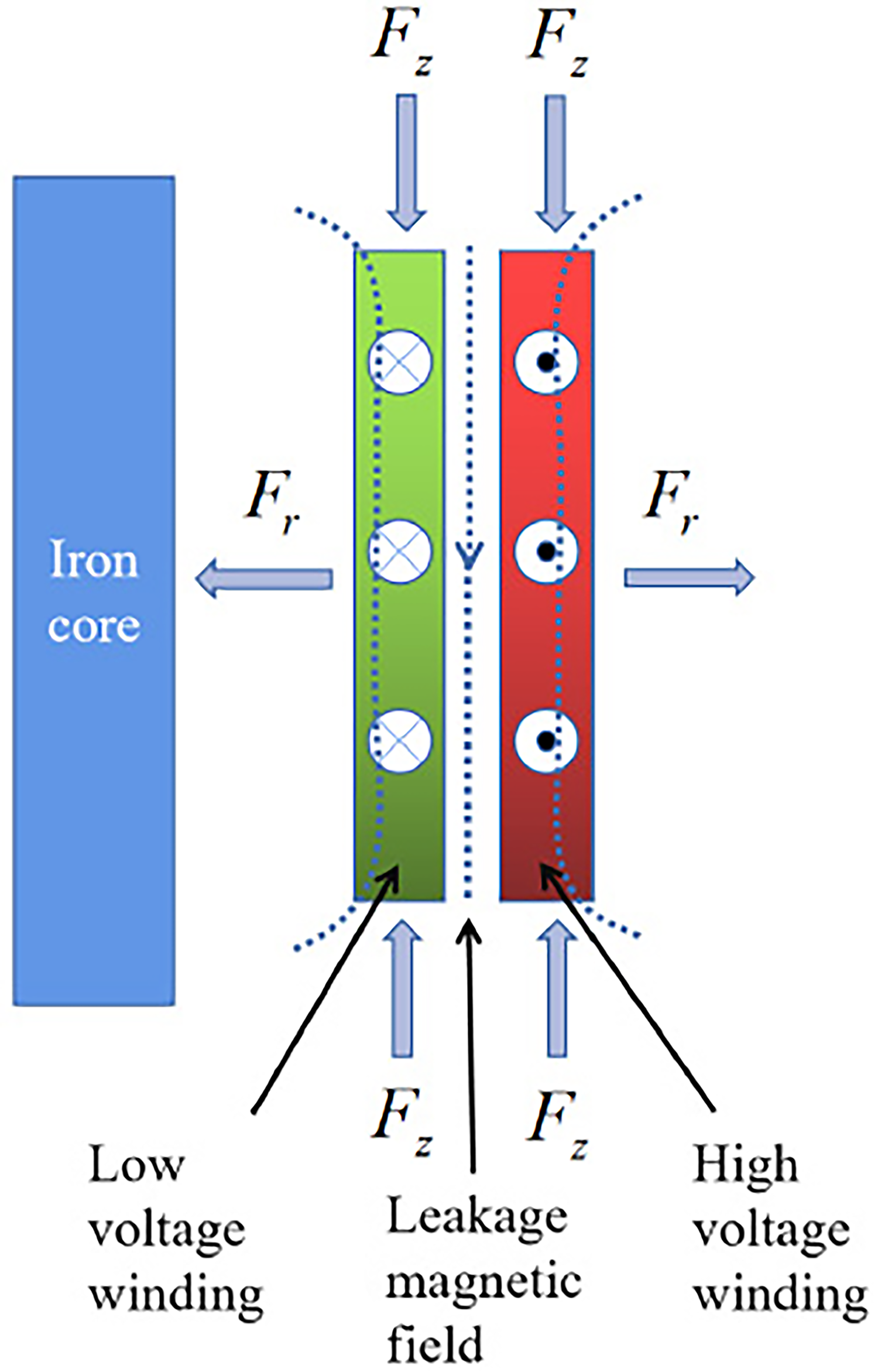
Schematic diagram of the winding magnetic field and force.
When the transformer is in steady state operation, the current in the winding can be obtained by the following formula:

The leakage magnetic field generated inside the transformer during operation can be regarded as a time-varying function. According to the Biot–Savart law, there is the following relationship between the flux leakage density B
t
inside the transformer and the steady-state current I:

The magnitude of the electromagnetic force received by the winding is:

Combine this formula with the following mathematical formula:

The magnitude of the electromagnetic force received by the winding can be obtained:

From this formula, it can be seen that the fundamental frequency of the electromagnetic force received by the winding is twice that of the power frequency. Additionally, since the acceleration is proportional to the electromagnetic force, the fundamental frequency of the vibration acceleration of the winding is also twice that of the power frequency. In the actual operation of the transformer, it will also be subjected to different degrees of harmonic components due to the influence of harmonics or material nonlinear characteristics.
In order to facilitate the study, the flux leakage density is usually decomposed into radial flux leakage density B
r
and axial flux leakage density B
z
. The axial electromagnetic force F
z
is generated by the interaction between the radial flux leakage density and the current, while the radial electromagnetic force F
r
is generated by the interaction between the axial flux leakage density and the current. Generally speaking, the axial force of the winding is large. The magnitude of the electromagnetic force received by the winding is:

Generally speaking, the axial force of the winding is relatively large, and excessive axial force causes severe axial vibration of the winding, leading to issues like winding looseness. This article primarily analyzes the axial force of the winding.
In the short-circuit process of the transformer, the voltage equation of the primary circuit of the transformer is as follows:

The short-circuit current obtained by solving Eq. (7) is:

Substitute this formula into formula (3) to obtain the winding electromagnetic force in short-circuit:

The inrush current during no-load closing [22] is:


Establishment of the finite element model
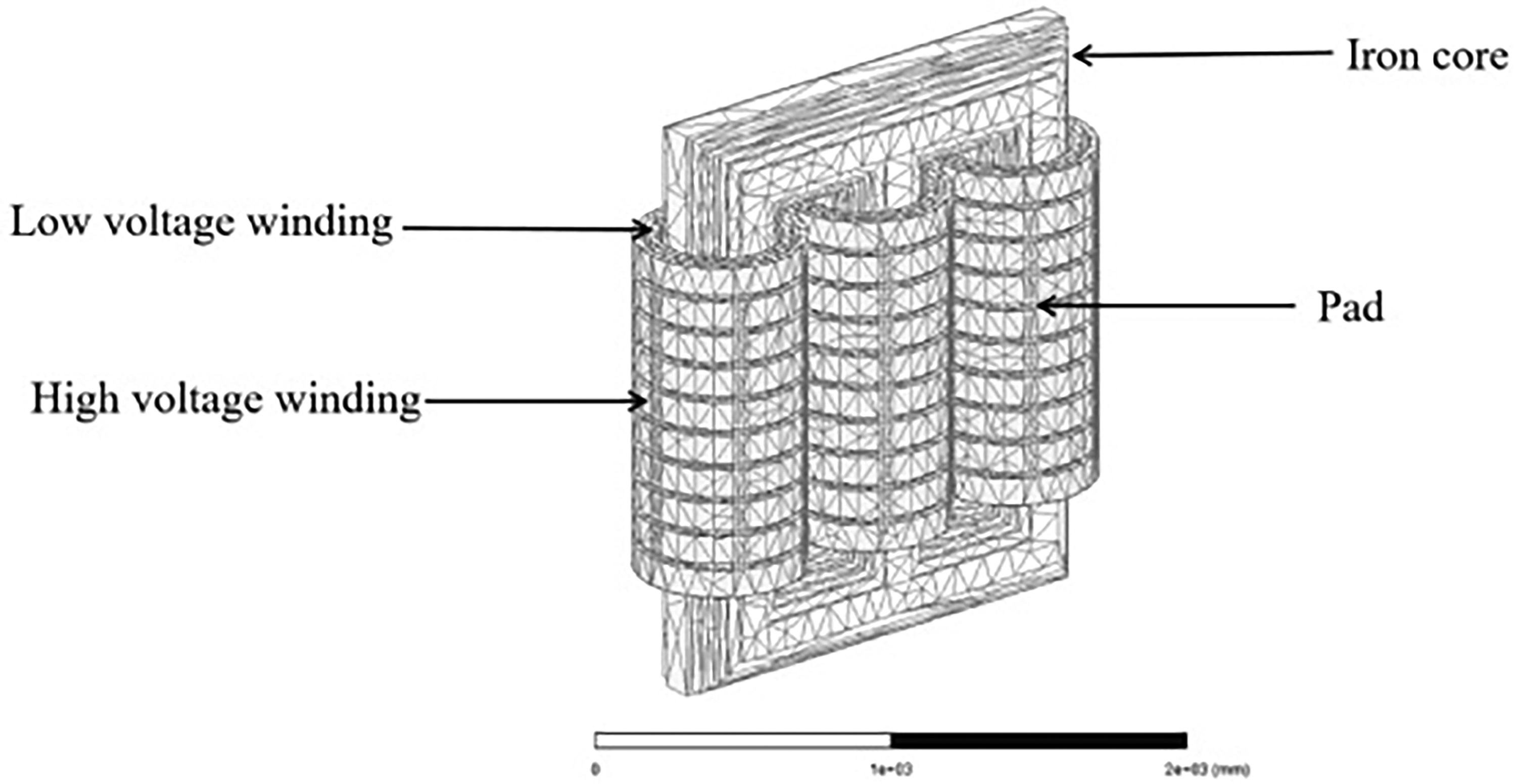
This paper presents a simulation analysis of a three-phase three-column transformer. To account for the complexity of the actual transformer structure and the computational limitations of computers, a simplified model is utilized to balance simulation accuracy and computer performance. The established finite element model of the transformer consists of essential components such as the iron core, winding, pad, and clamp. As shown in Figure 2.
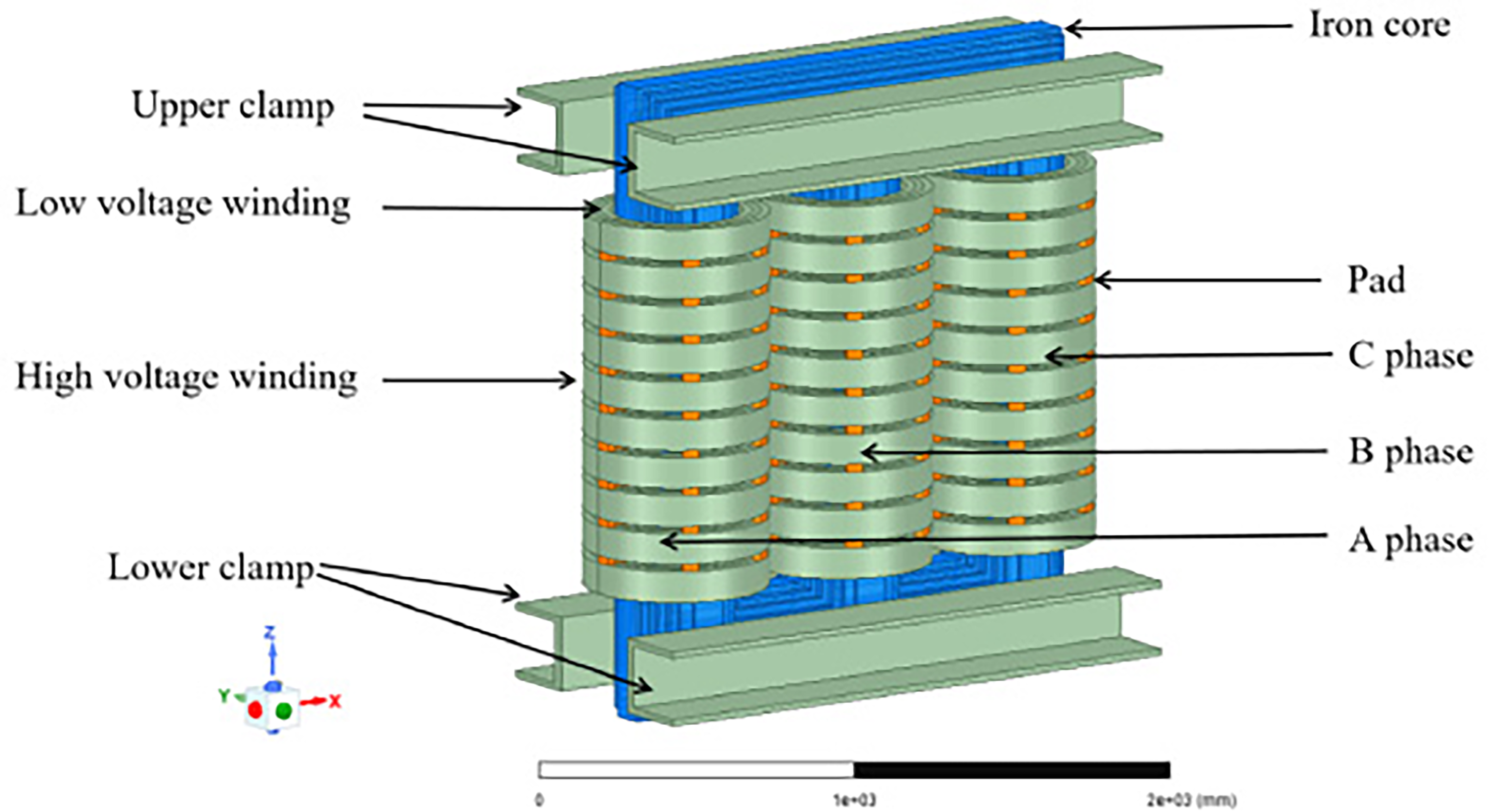
Finite element model of the transformer.
The main parameters of the transformer are shown in Table 1.
Main parameters of the transformer.

In order to facilitate the analysis of the electromagnetic force of different winding cakes, the layers of high and low pressure are numbered from 1 to 10, starting from the bottom and moving upwards, as shown in Figure 3.
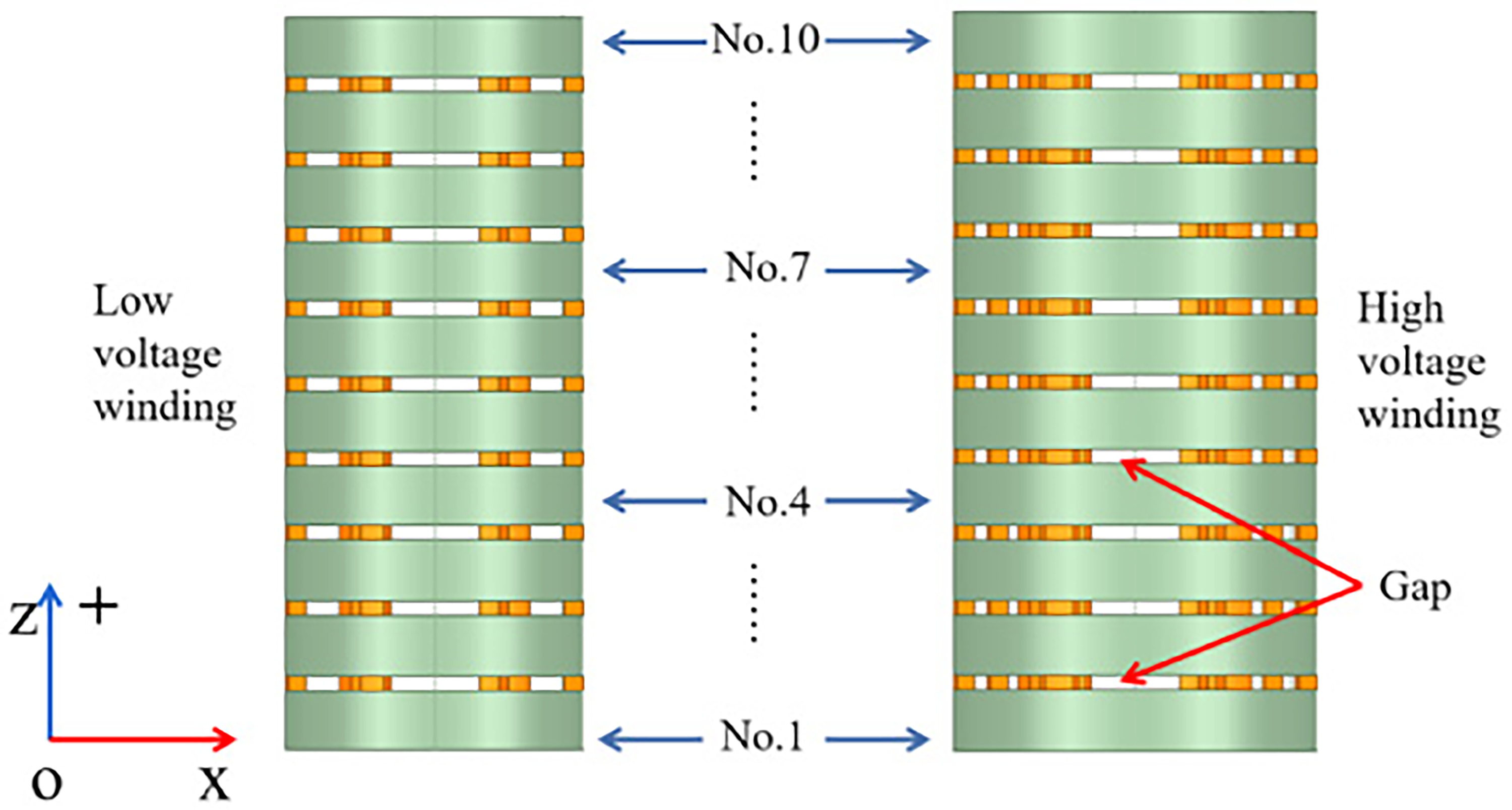
Numbering diagram of winding cake.
To complete the model simulation, it is necessary to set the material parameters for each part of the model structure. The transformer core studied in this paper is made of laminated silicon steel sheets, and its magnetization characteristics are determined by its nonlinear B-H curve (Figure 4). The winding material is copper, which is sourced from the material library. The pad material is made of insulating cardboard, and the clamp material is steel.
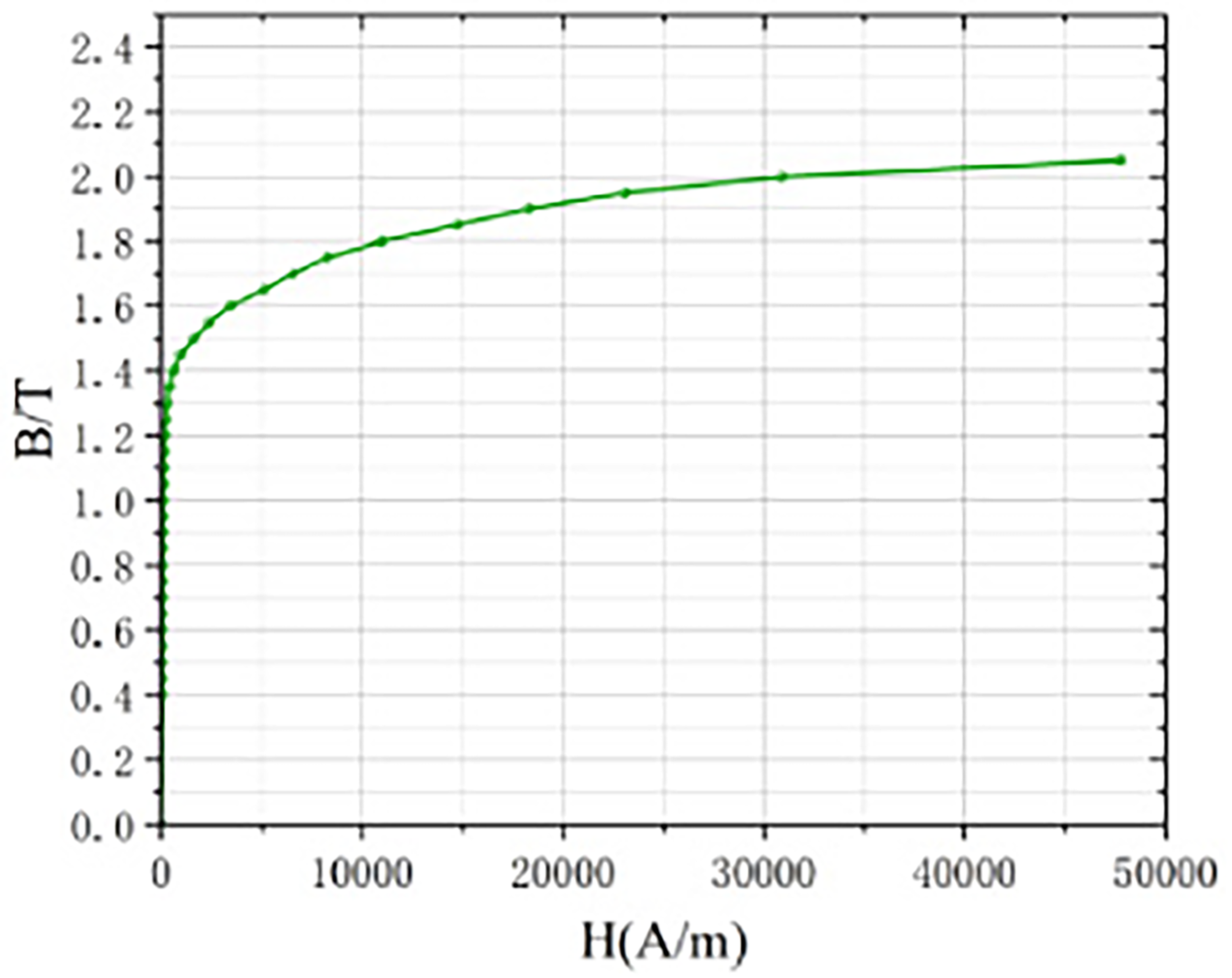
B-H curve of the core.
After material parameter setting, boundary conditions need to be set. In this paper, the default Neumann boundary conditions are selected, Then the transformer is meshed and divided by tetrahedral mesh. Considering the calculation accuracy and computer performance comprehensively, the iron core and high and low voltage winding are meshed by 50 mm and 40 mm respectively. The meshing results are shown in Figure 5, in which the number of meshes is 44035 and the number of winding meshes is 28,808. The number of pad grids is 7225 and the number of core grids is 8002.
Mesh generation results.
The electromagnetic force in a transformer’s winding is produced by the collective influence of the current flowing through the winding and the leakage field. Prior to investigating the electromagnetic force in the winding, an examination of the surrounding leakage field is necessary. As shown in Figure 6, A line segment is taken along the winding axis at positions A and B to observe the distribution of the leakage field between the high and low windings.
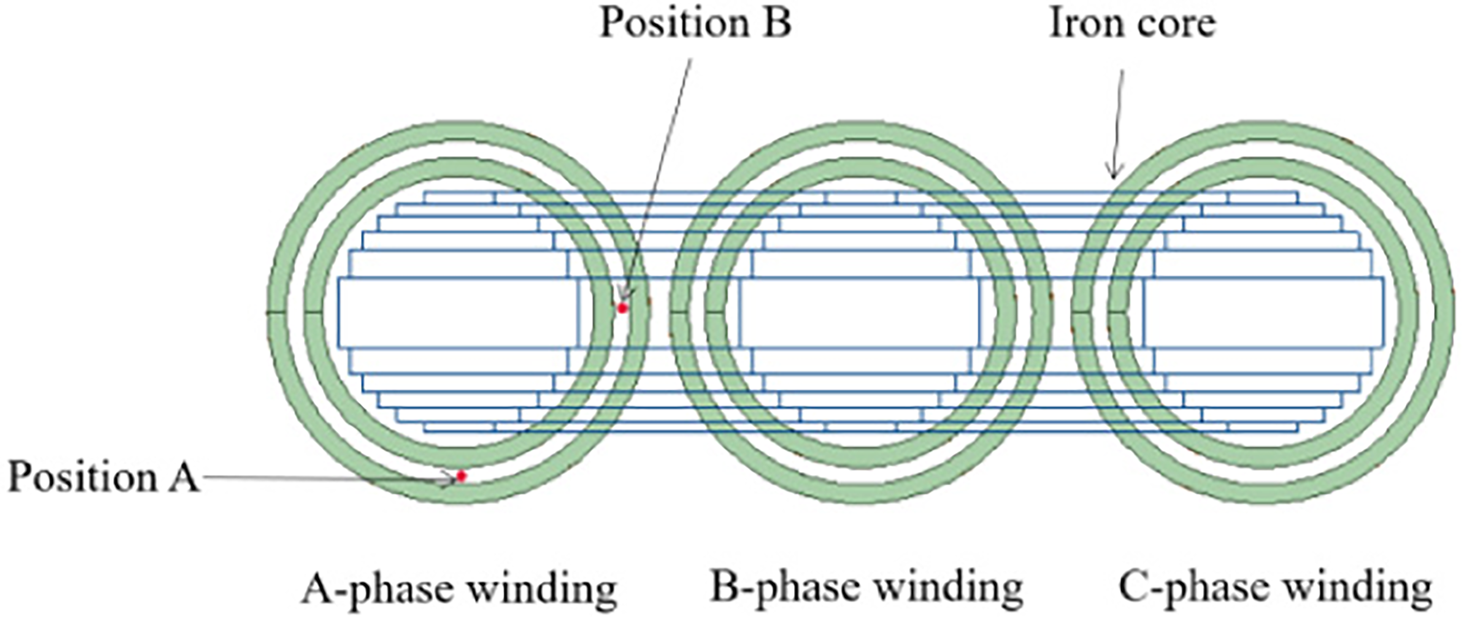
Position of magnetic flux leakage observation line.
In this paper, the analysis focuses on the three-phase short-circuit fault in transformers, which is considered the most severe. In order to analyze the combined effects of electric and magnetic fields, a simulation analysis of transformer windings with short-circuit current excitation is conducted using field-circuit coupling. The primary side of the transformer is subjected to the rated voltage, while the secondary side is short-circuited. The simulation time is set to 120 ms, with each step being 1 ms. The simulation results of each step are saved. The simulation results of the A-phase high-low voltage current under short-circuit working conditions are shown in the figure.
As can be seen from Figure 7, the current direction of high and low voltage winding is opposite, which conforms to the principle. The high and low voltage windings of phase A reach their peak short-circuit currents at 9 ms. The peak short-circuit current of the high voltage winding is 7565 A, which is 31.62 times the rated current. The peak short-circuit current of the low voltage winding is 13818 A, which is 18.15 times the rated current. Even after the short-circuit current stabilizes, the value remains quite large. The interaction between a large current and the leakage magnetic field will generate a significant electromagnetic force, which can affect the winding. At the same time, the winding will also generate a significant amount of heat within a short period, leading to an increase in the temperature of the winding. It will also cause insulation aging or even failure, which poses a significant threat to the stable operation of the transformer.
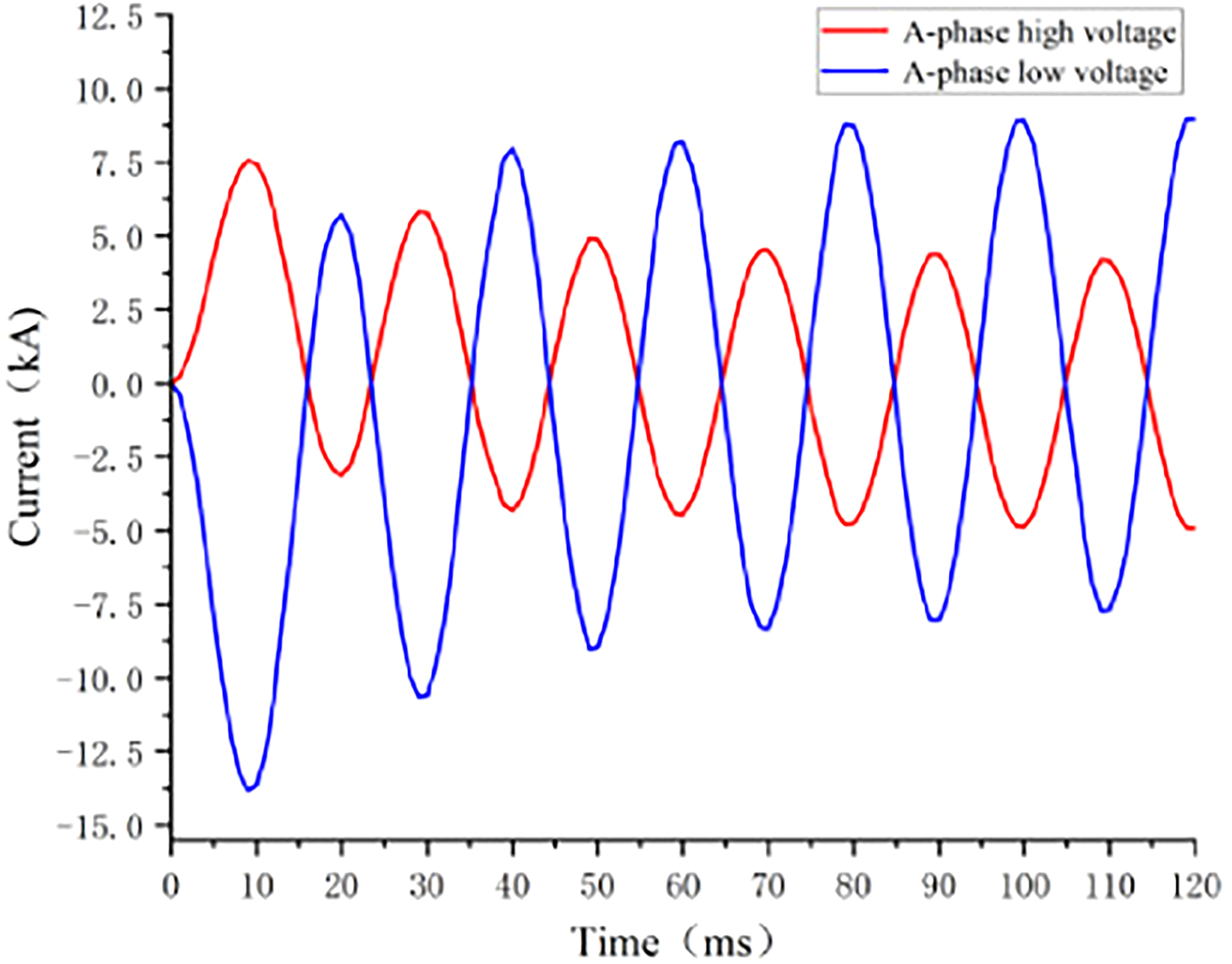
Phase A short-circuit current.
The leakage magnetic field at the peak time of the short-circuit current, i.e., 9 ms, is selected for checking. As can be seen from the Figure 8, the distribution law of the leakage magnetic field at different positions of A and B between the high and low voltage windings is basically the same. It shows a pattern of high and low variation, which is due to the separation of different winding layers by pads, creating gap. These gaps have no current flowing through them, resulting in a smaller leakage field strength compared to the area around the winding. Additionally, line B is located in the core window and is influenced by the upper and lower iron yoke, causing slightly smaller magnetic leakage at both ends compared to line A. The strength of the magnetic leakage field at both positions constantly changes with the axial height of the winding. The maximum value is approximately 4.2 T, and the empty channel area between each wire cake of the winding also reaches about 3.2 T. It can be inferred that the large current flowing through the winding during a short-circuit event results in a significant leakage magnetic field around the winding.
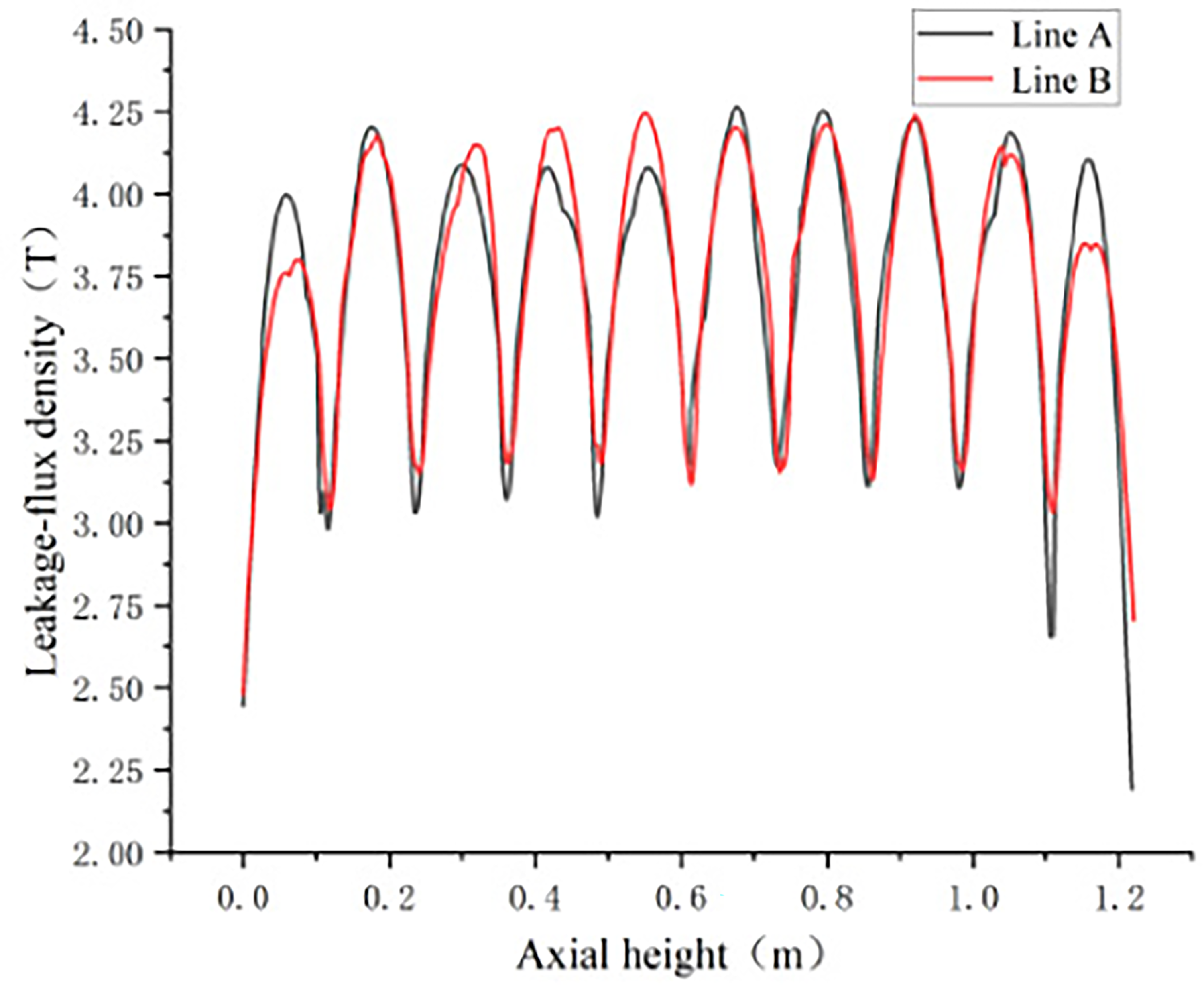
Leakage magnetic field at positions A and B.
The analysis focuses on the electromagnetic force received by the winding. The axial electromagnetic force received by the A-phase high and low voltage winding at the peak moment of short-circuit current is shown in Figure 9.
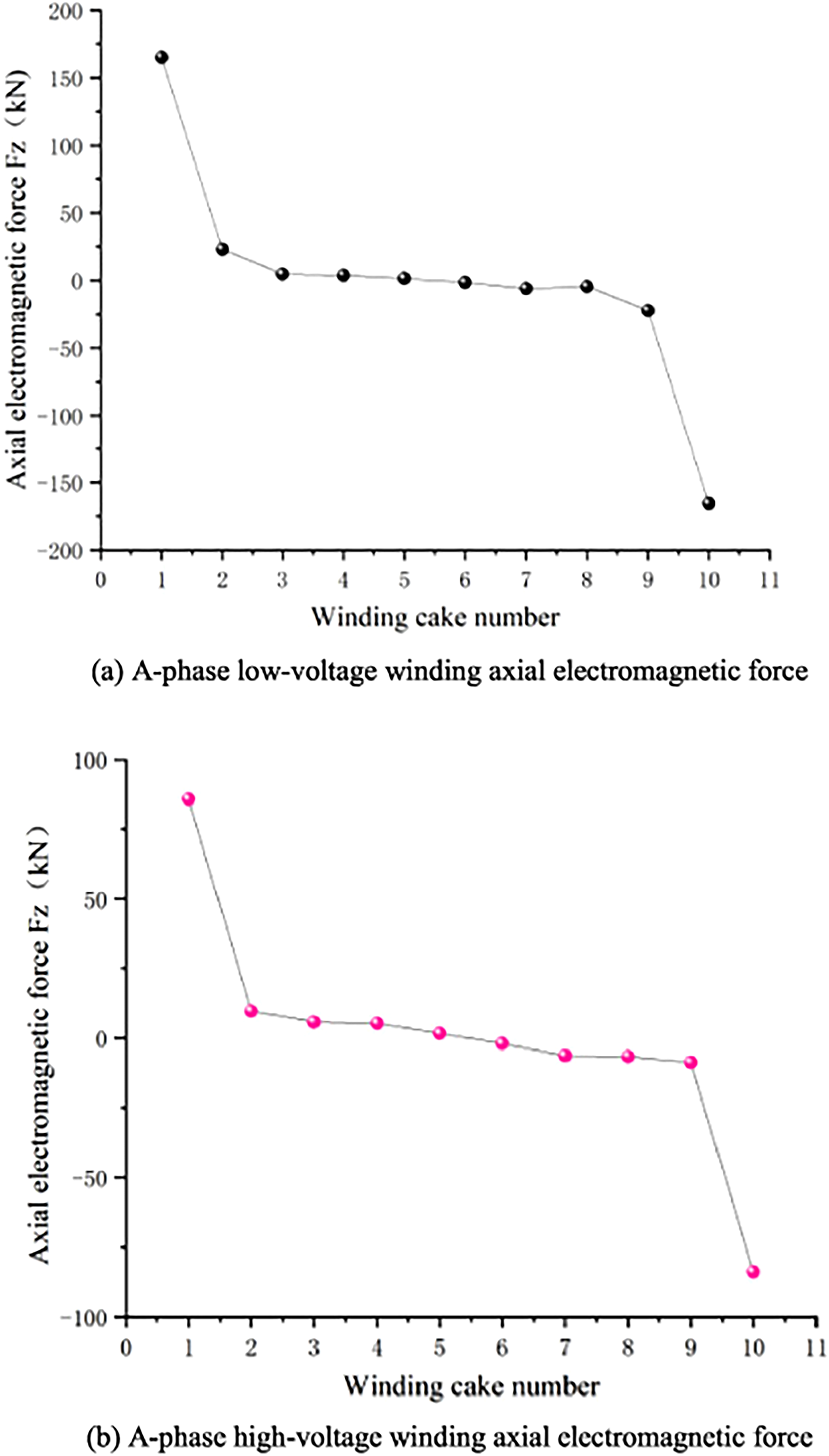
Axial electromagnetic force of A phase high and low voltage windings.
As can be seen from the figure above, the law of axial electromagnetic force received by the high voltage and low voltage windings is consistent. The axial electromagnetic force is greater at the upper and lower ends of the winding and decreases towards the middle. The axial height shows symmetrical distribution between the upper and lower ends of the winding.
The positive and negative values in the figure above indicate the direction of the electromagnetic force. Specifically, the force is upward in the positive direction of the z-axis and downward in the opposite direction. The axial electromagnetic force received by the low-pressure No. 1 wire cake is 164.92 kN. The axial electromagnetic force received by the No. 10 wire cake is −165.59 kN. The electromagnetic force received by the No. 2 to No. 9 wire cakes is less than 25 kN. The axial electromagnetic force received by the No. 5 and No. 6 wire cakes located in the middle is the smallest. They are 1.52 kN and −1.41 kN, respectively. The overall force of the high-voltage winding is less than that of the low-voltage winding. The axial electromagnetic force of the high-voltage No. 1 wire cake is 85.73 kN, the axial electromagnetic force of the No. 10 wire cake is −83.80 kN, and the axial electromagnetic force of the No. 2 to No. 9 wire cakes is less than 10 kN. The force of the No. 5 and No. 6 wire cake is 1.78 kN and −1.87 kN. At the peak moment of the short-circuit current, the axial electromagnetic force on the high and low voltage windings is very large. Although the impact time of the peak current is very short, it will still have a certain destructive effect on the winding. If the winding is subjected to multiple impacts, the cumulative effect can cause it to exceed its load-bearing capacity, resulting in permanent plastic deformation. This deformation can lead to instability and collapse of the winding, which may cause a major transformer failure.
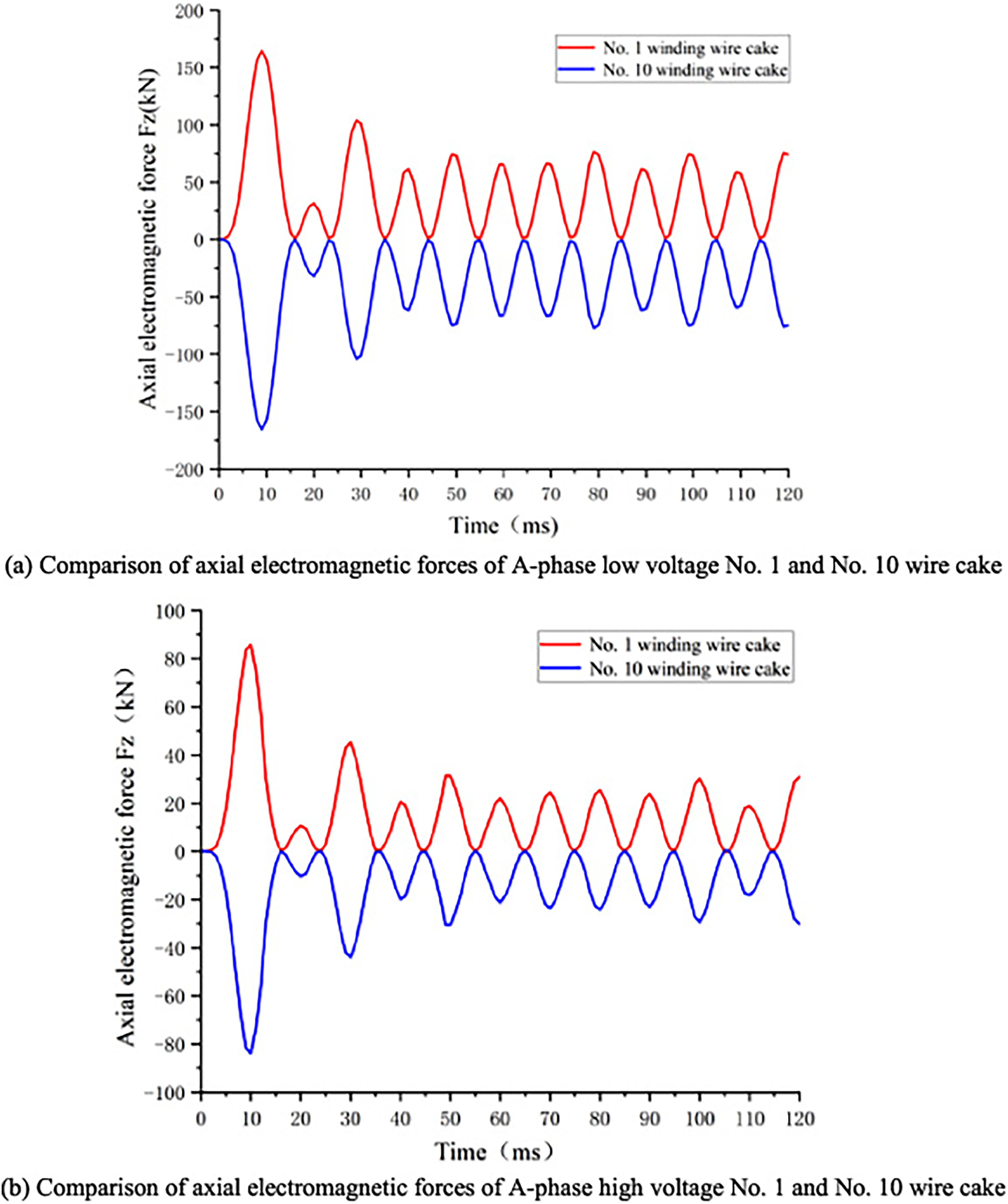
Comparison of axial electromagnetic forces of different linear cakes at high and low pressure in phase A.

Simulation model of no-load transformer inrush current.
Taking the No. 1 and No. 10 wire cake as examples, the dynamic process of the change in axial electromagnetic force over time in the high and low voltage windings of phase A is analyzed. Figure 10 is the comparison of axial electromagnetic force of different A-phase wire cakes with high and low voltages. It can be seen from the Figure 10 that the change in axial electromagnetic force of the high and low voltage windings follows a similar pattern over time. The No. 10 wire cake at the top is subjected to the downward electromagnetic force, which compresses the winding in the axial direction. As a result, the low voltage winding experiences higher extrusion pressure. Additionally, it can be observed from the figure that once the axial electromagnetic force of the winding stabilizes, its frequency is twice that of the current. During the entire short-circuit current process, the direction of the axial electromagnetic force acting on the winding remains unchanged. This is because the direction of the electromagnetic force is determined by both the direction of the current and the direction of the magnetic field leakage. The change in current direction also results in a change in the direction of the leakage magnetic field, while the direction of the electromagnetic force remains unchanged.
To simulate and analyze the electromagnetic and force conditions of transformer windings under no-load closing inrush current, it is essential to obtain the no-load closing inrush current. However, editing the closing circuit with no load in Maxwell is inconvenient due to the absence of open-circuit editing and equipotential points. To overcome this limitation, this paper utilizes the electrical system module library PSB in Matlab/simulink to construct a simulation model for the no-load closing inrush current of a transformer. Additionally, the three-phase voltage-current measurement module is employed to export the simulation waveform of the no-load closing inrush current into the Matlab workspace. This will facilitate the subsequent addition of excitation to the transformer windings.
The Figure 11 shows the model that was built, which primarily utilizes the power module, measurement module, circuit breaker module, and transformer module. The power module provides the rated primary voltage of the transformer, which is 35000 V. The measuring module measures the current. The circuit breaker module simulates different closing angles by adjusting its closing time. The transformer module is a three-phase double-winding saturated transformer module, and the connection group is set as Yd11. The module parameters are set by per unit value (pu). For most transformers, the maximum remanence is generally 0.5Φ m ∼ 0.8Φ m (Φ m is steady-state flux amplitude). This paper conducts a simulation analysis of the no-load closing inrush current of the transformer under various conditions by altering the angle of remanence and closing. The results are illustrated in the Figure 12.

Relationship between peak value of A phase inrush current, remanent magnetism and closing Angle.
From 0° to 90°, with a closing angle increment of 15°, in the simulation of no-load closing inrush current under different closing angles and remanence levels, the peak value of inrush current increases with higher remanence and decreases with smaller closing angles, while keeping the closing angle constant.
As shown in the Figure 13, the most severe case, i.e. A-phase remanence, is 0.8Φ m . When the closing angle is 0°, the peak value of inrush current reaches 2092 A, which is 8.74 times the rated current. At this time, the winding will be subjected to a significant electric force, which can impact the winding, compromise its structural stability, and ultimately lead to winding deformation and mechanical failure.

Inrush current when the closing Angle is 0° and remanent magnetic Φre = [0. 8Φ m , −0. 4Φ m , 0. 4Φ m ].
The no-load closing inrush current waveform when the A-phase remanence is 0.8Φ m is loaded into the primary side winding of the transformer as excitation, which is the high voltage winding. The simulated inrush current waveform is shown in the Figure 14.

The inrush current simulation waveform.
Similarly, check the magnetic field leakage at positions A and B at 9 ms, as shown in Figure 15. The distribution of the leakage magnetic field in the case of magnetic inrush current shows a pattern of high and low changes, similar to the distribution in the case of a short circuit. However, the overall amplitude is small, with the maximum magnetic field intensity reaching 1.12 T. Due to the saturation of magnetic flux in the core, the magnetic leakage at the position of line B in the core window is greater than that at the position of line A overall, that is more pronounced at the end.

Leakage magnetic field at positions A and B.
The axial electromagnetic force of each winding wire cake at the peak of the inrush current is analyzed, as shown in Figure 16. Because the secondary side of the transformer, i.e. the low voltage side, is open in the no-load closing condition, there is no current flowing through the winding. As a result, the winding is not affected by the electromagnetic force, and only the high voltage winding is analyzed. As can be seen from the figure above, the axial electromagnetic force of the winding is also larger at both ends due to the impact of the inrush current. The small rule in the middle is consistent with that under the action of short-circuit current, but under the action of inrush current, the axial electromagnetic force changes more smoothly with the winding wire cake. Numerically, the No. 1 wire cake is subjected to an axial electromagnetic force of 51.42 kN, the No. 10 wire cake is subjected to −51.76 kN, and the forces on the other wire cakes are basically symmetrical. No. 5 and No. 6 wire cakes have the least force, which are 1.19 kN and −1.14 kN respectively.
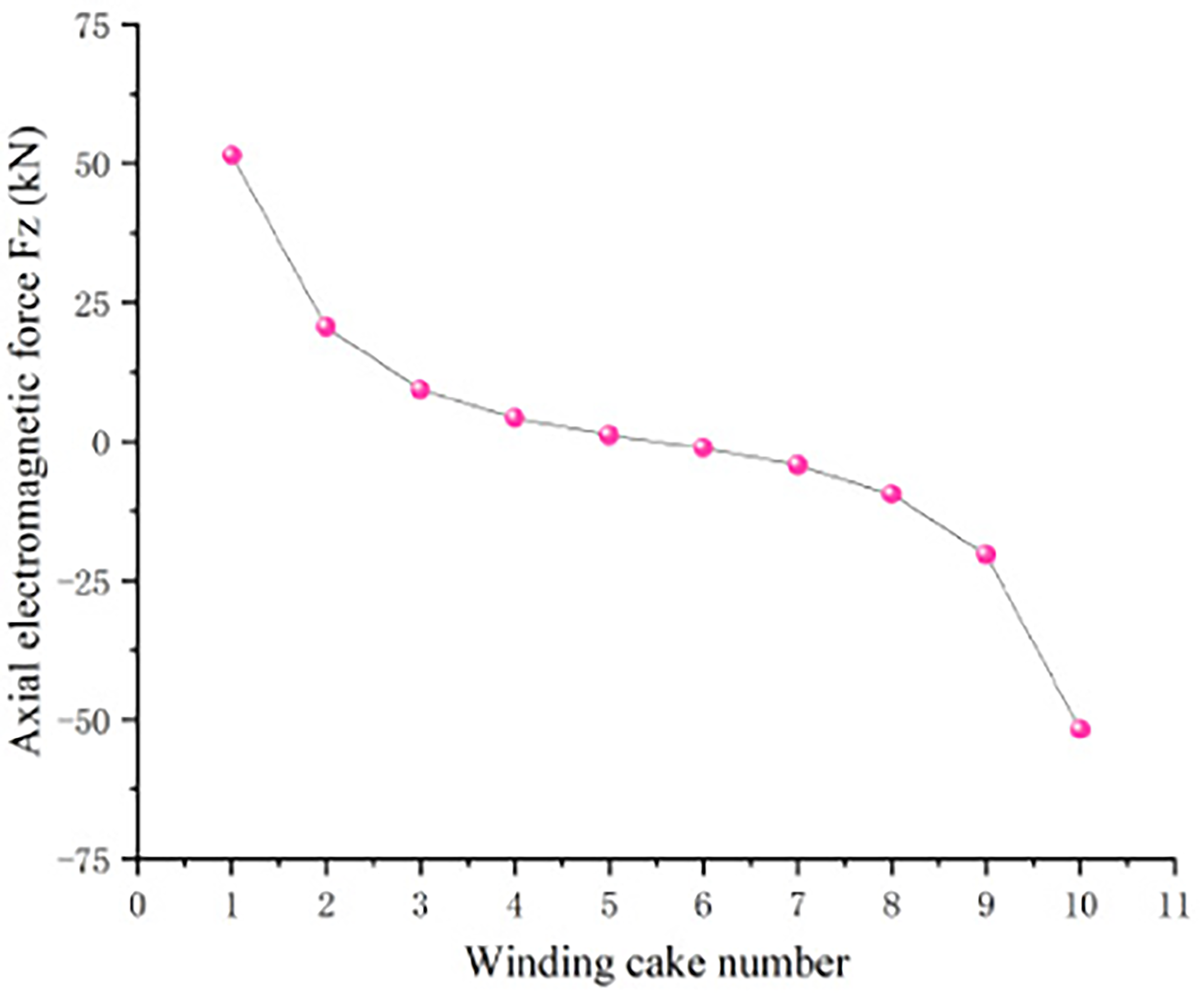
Axial electromagnetic force of high voltage winding.

Comparison of electromagnetic forces of different wire cakes in high voltage windings.

Frequency domain components of the electromagnetic force.
The dynamic stress process of winding wire cake under the action of inrush current is analyzed, as shown in Figure 17. The force exerted by No. 1 and No. 10 wire cake is similar, but the direction is opposite. The axial electromagnetic force waveform received by the winding is similar to the current waveform, both of which have a discontinuous angle. Different from the short-circuit current, the axial electromagnetic force has 6 impacts on the winding within 120 ms, and 12 impacts on the short-circuit current. Additionally, the speed of electromagnetic force attenuation differs under the two working conditions. In the same time, the axial electromagnetic force of the short-circuit attenuates from 85.73 kN at the peak to 18.86 kN at 110 ms, and decreases to 22% of the peak electromagnetic force. The inrush current decreases from 51.42 kN to 21.67 kN within 110 ms, and reaches 42% of the peak electromagnetic force.
After the electromagnetic force stabilizes, a Fourier transform is performed on the axial electromagnetic force of the No. 1 wire cake of the high voltage winding under the two current flows to obtain the frequency domain components of the electromagnetic force, as shown in Figure 18. It can be observed that both contain DC components, which are more pronounced at a frequency of 100 Hz, and also include some frequency doubling components at 100 Hz. However, the electromagnetic force exhibits a higher proportion of higher harmonic content when subjected to an excitation insurge current.
The comparison is shown in Figure 19, it can be observed that when the amplitude of the inrush current reaches approximately 30% of the amplitude of the short-circuit current, the same short-circuit current can generate an axial electromagnetic force.

Comparison of axial electromagnetic force.
This paper presents a comprehensive simulation analysis of the leakage field, axial electric force, and dynamic changes in the winding when exposed to short-circuit current and no-load closing inrush current in a transformer. To carry out this analysis, a finite element model of the transformer is established. The conclusions are summarized as follows:
(1) Though the trend of the leakage magnetic field strength between the high and low windings shows the same high and low variation under the two overcurrent conditions, the amplitudes differ inside and outside the iron core.
(2) Under the two overcurrent conditions, the peak axial electromagnetic force experienced by each coil cake of the transformer windings shows a trend of being larger at the upper and lower ends and smaller in the middle. The axial electromagnetic force is symmetrically distributed along the height of the winding. Under the influence of the inrush current, the axial position of the coil core undergoes a gradual change.
(3) In the process of dynamic over time, the waveform of time, the electromagnetic force waveform is similar to the waveform of the overcurrent waveform. Because the electromagnetic force attenuation speed of the inrush current is slower than that of the short-circuit current, the duration is longer. However, the impact on the winding is less compared to that of the short-circuit current.
(4) The frequency domain components of the axial electromagnetic force generated by the two overcurrent currents mainly consist of DC and 100 Hz components, both of which also contain higher-order harmonics. However, under the inrush current, higher-order harmonics account for a larger proportion and are more easily able to cause resonance.
(5) The inrush current’s electromagnetic force only affects the primary winding, whereas the short-circuit current affects both the high and low voltage windings. However, the low inrush current can generate an electromagnetic force that is equivalent to the short-circuit current. Additionally, the inrush current has a high frequency and a prolonged duration. Although a single or a few impacts cannot directly cause failures in the winding, the accumulation of long-term operation of the transformer can increase the risk of failure and affect its service life.
This paper’s research establishes a foundation for further analyzing the cumulative effects of transformers under overcurrent impacts such as short-circuit current and inrush current, as well as the stability of winding forces. Moreover, it explores the study of the axial electromagnetic force acting on the winding during excitation current. The primary objective of this study is to enhance transformer design, improve the axial stability of winding ends, and reduce the occurrence of faults in transformer windings.
Footnotes
Acknowledgement
This work was supported by the National Natural Science Foundation for Young Scientists of China under Grant 51707128.