
Abstract
Based on the radiation of the transient electromagnetic fields in lightning discharge channel, we establish the simulated model of lightning channel in the laboratory and analyze the data and waveform, which are received by the low frequency magnetic antenna and the plate capacitance electric field change instrument. Thus we draw some conclusions. In the experiment, the energy of lightning current is mainly concentrated in the low-frequency stage, and the difference of energy between two frequency point decreases with the frequency growth. The waveform of plate capacitance appears after that of magnetic antenna. As the impulse current increasing, the coupling amplitude and energy of the antenna have an increased trend and the growth of the magnetic antenna is more stable. When distance is further, the amplitude and energy of the antenna present a tendency of decrease. And the forepart is steep and the back is flat. The results have some significance on the research of lightning return stroke and lightning electromagnetic fields.
Keywords
Introduction
Lightning is a kind of electromagnetic pulse phenomenon of frequently and high-intensitive in nature. The human study of lightning has more than 200 year’s history. The protection technologies of direct lightning flashes and conduction surge have been developed to be more mature by now. In contrast, the study of the lightning electromagnetic pulse has yet to be deepened [1]. Radiation effects of lightning electromagnetic fields are gradually attracted attention to people in the 1970s. As the main parameter of lightning, electromagnetic pulse is an important precondition to study lightning and its regularity. A mass of experiments have been carried out in more thunderstorm region [2,3]. A large number of experimental data obtained by artificial initiation provide information for the natural lightning study. However, due to the high cost and low success rate, it is great necessary to study the temporal and spatial distribution of lightning electromagnetic pulse from the theoretical point of view, which can provide the theoretical basis for laboratory simulation and lightning protection research.
Antenna is widely used in modern communication technology because of its advantages of light weight, simple structure and wide band. The dipole method is widely used in antenna theory. It just needs to know the temporal and spatial distribution of electrical current density, which is suitable for calculating lightning radiation electromagnetic fields. V.A.Rakov and M.A.Uman classify the lightning return stroke model into four categories according to the control model [4–8]. They are gas dynamics model, electromagnetic model, distributed circuit model and engineering model. The latter three models can calculate the electromagnetic fields of lightning return stroke directly. But the engineering model does not attach more attention to the physical factors of lightning return strokes. Mostefa Boumaiza proposed a study on the coupling of lightning and overhead distribution lines [9]. Jianqiang Wang investigated a devastating situation of the equipment in aircraft which is produced by the short-wave antenna coupled the energy of lightning electromagnetic pulse when the body of aircraft suffered by direct lightning [10] . The equivalent circuit model of the antenna in receiving status is established by Xiangchao Li [11]. They proposed an approach to suppress the lightning electromagnetic pulse for receiver by utilizing lightning protection device. However, there are few researches on analysis of different antennas coupling lightning electromagnetic fields. In this paper, we use the low frequency magnetic antenna and the plate capacitance electric field change instrument (hereinafter, the magnetic antenna and the plate capacitance) for coupling lightning electromagnetic fields. The voltage amplitude and energy received by the antenna are compared and analyzed. It is found that the magnetic antenna is more sensitive to the lightning current, while the change of distance has more impact on the plate capacitance. The results have great significance on the research of lightning return stroke and lightning electromagnetic fields.
Theoretical analysis
Theory of lightning electromagnetic radiation fields
To calculate the lightning return stroke electromagnetic fields, based on a variety of engineering models, foreign scholars approximate the earth to a good conductive plane (σ →∞). They take no account of the effects of charge within the cloud, and assume that there is infinite space around the channel. The lightning return stroke channel is simplified to a straight line that is perpendicular to the ground. The return stroke can be seen as the process of the return stroke current rising along the channel. The boundary condition is satisfied by adding an underground mirror channel, which is the antenna model of lightning return stroke process [12]. As shown in Fig. 1.
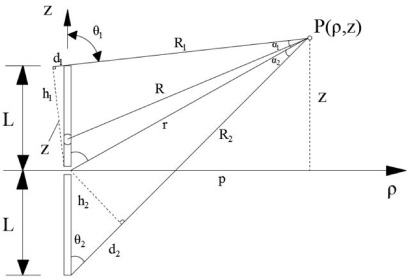
Antenna model of lightning return stroke.
According to the characteristics of current distribution, the antenna emits the magnetic fields which only have the 𝜑 directional component in the cylindrical coordinate system [13,14]. It takes time for the current to rise from the bottom of the channel, thus the height where the observers see at the point P has a delay in moment t [15,16]. For the mirror current, since the distance between the mirror small dipole and the observation point is different from the actual small dipole, the height of the mirror current in the mirror channel is different at the observation point [17].
If the observation point
The equivalent circuit of receiving antenna in the frequency domain is shown in the Fig. 2. The antenna is equivalent to the source with internal impedance Z
A, the induction electromotive force U
0 is the open circuit voltage of the antenna, and Z
L is the terminal load. The following conclusions can be drawn according to the reciprocity theorem: For any receiving antenna, the supply load current I is proportional to directivity function F (θ, 𝜙) that the antenna is used as a transmitter. Therefore, the directivity of the receiving antenna is exactly the same as that used for transmitting antennas. Equivalent electromotance of the receiving antenna is [18],
According to the circuit theory, the output power is largest when Z
L and Z
A conjugate match. The maximum output power of the antenna is,
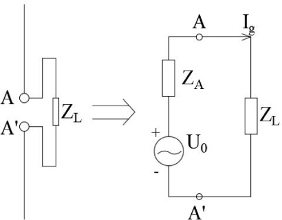
The equivalent circuit of receiving antenna.
Experiment program
In this experiment, ICGS (Impulse Current Generation System) was adopted to simulate the lightning current. The experimental model is shown in Fig. 3. The metal rod about 1.5 meters is placed vertically on the ground. Both bottom and top are connected with the ICGS by cable to form a closed loop. The 8/20 μs simulated lightning current is applied to both ends of the metal rod. Here, the metal rod as a simulated lightning channel emits the lightning electromagnetic pulse. The lightning impulse current is applied from 5 kA to 11 kA with 1 kA step length. The magnetic antenna (bandwidth 30--300 kHz) and the plate capacitance (10 Hz--5 MHz) are placed away from metal bar from 3 to 15 meters, and the step length is 2 meters. The plate capacitance is ground. The GDS 3502 digital storage oscilloscope is used to collect the same impulse current waveform coupled by the magnetic antenna and the plate capacitance. The collected antenna voltage wave is processed. Calculating and analyzing the coupled voltage amplitude and energy.
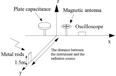
The schematic diagram of antenna coupling lightning electromagnetic fields.
In Fig. 4, the energy of lightning current is mainly concentrated in the low-frequency stage [19,20], but it also has a certain proportion of the energy in the high-frequency stage. In the low-frequency stage, the difference of energy between two frequency point decreases with the frequency growth.
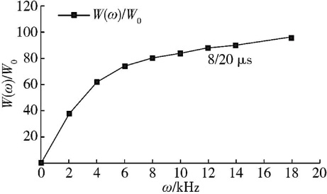
Cumulative frequency scattergram of the energy rate.
The magnetic antenna and the plate capacitance are used to couple simulated electromagnetic wave in the distance of 13 meters from the metal rod. The typical voltage waveform of the coupled antenna under the 15 kA lightning impulse current is shown in Fig. 5. Where 1 is the waveform of the magnetic antenna and 2 is the waveform of the plate capacitance.
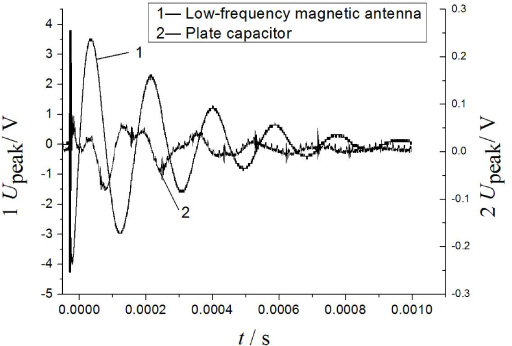
The typical voltage waveform of the coupled antenna under the 15 kA lightning impulse current.
According to the voltage value of the coupled lightning wave in Fig. 5, the waveform shapes of plate capacitance and magnetic antenna are roughly the same. They are all damped oscillation waves. But the waveform of plate capacitance obvious appears early about 0.15--0.5 ms than that of magnetic antenna. This is because the time constant of the plate capacitance we used is 0.1 ms. It has the higher sensitivity and faster responses to receive the signals. In addition, it can be also seen from the Fig. 5 that the coupled magnetic field waveform amplitude of magnetic antenna is great significantly than that of the electric field waveform. According to analysis of the results of actual measurement lightning current, the energy of lightning current is mainly concentrated in the low-frequency stage. Therefore, the coupled voltage value of magnetic antenna is more obvious. However, the received signal attenuation rate of magnetic fields is less than the electric field signal. Compared with 93.3% in attenuation rate of the plate capacitance, the voltage amplitude of magnetic antenna attenuates from 3.5 V to 0.5 V, the attenuation rate is 85.7% in 0.6 ms. As the impulse current increases, the fluctuation of the magnetic antenna amplitude is weaker and the amplitude tends to linear growth. As shown in Fig. 6, it is the scattergram of voltage wave amplitude coupled lightning electromagnetic wave. The metal rod is placed 9 meters away from the magnetic antenna and the plate capacitance, and the range of simulated lightning current is from 5 kA to 15 kA.
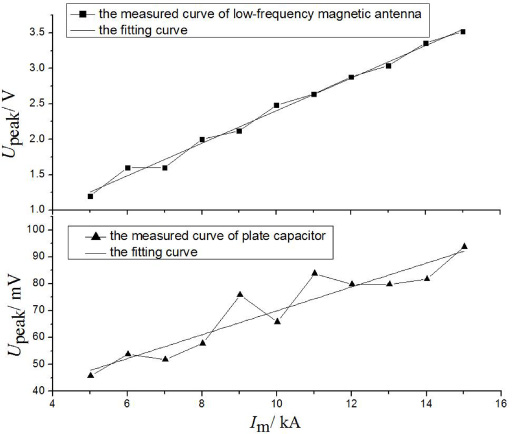
The tendency chart of the antenna coupling voltage amplitude at 9 meter.
From Fig. 6, it is obvious that the coupling voltage amplitude of the antenna have an increased trend as the impulse current increasing. But it is not completely linear. There are also several cases that the lightning current is high but the amplitude of received voltage is low. The main reason is that the lightning current has a gradient change when the experiment was conducted with ICGS, which causes the frequency spectrum of lightning current to change. But this is not affected to the holistic voltage increase. Figure 7 describes the coupled energy tendency chart that the magnetic antenna and the plate capacitance with the lightning electromagnetic increase. Where y-coordinate is the integral of antenna coupled lightning electromagnetic fields voltage square for time. According to the reciprocity theorem of antenna, the relation between power and voltage of receiving antenna are quadratic. Therefore, when the distance is certain, it is evident from Fig. 7 that the energy of antenna coupled lightning electromagnetic fields is quadratic rise with impulse current. The energy fluctuation of the magnetic antenna is obvious weaker than the plate capacitance.
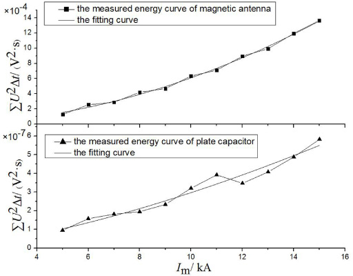
The tendency chart of the antenna coupling energy.
As shown in Fig. 8, the amplitude tendency chart of antenna with distance further is described when the impulse current is 9 kA. The range of distance is from 3 to 15 meters. As we can see from the figure, the voltage amplitude of the antenna coupled electromagnetic fields is decreasing as the distance increases, but it is not linear. Instead, it presents a tendency that the forepart is steep and the back is flat. Besides, the change of the plate capacitance is the most obvious, and the waveform has a certain distortion, the voltage peak is weakened, as shown in Fig. 5. According to the formulas (1) and (2), the magnetic field intensity is inversely proportional to the distance from the magnetic antenna to metal rod and the electric field intensity is inversely proportional to the square of the distance, which renders the change of distance more sensitive to the plate capacitance waveform. For example, from 3 to 9 meters, the voltage amplitude of magnetic antenna falls by about 54.2 percent, while the plate capacitance decreases by about 82.7 percent. It is evident from the energy changes processed in Fig. 9.
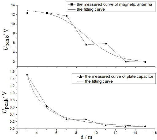
The tendency chart of the antenna coupling voltage amplitude under the 9 kA.
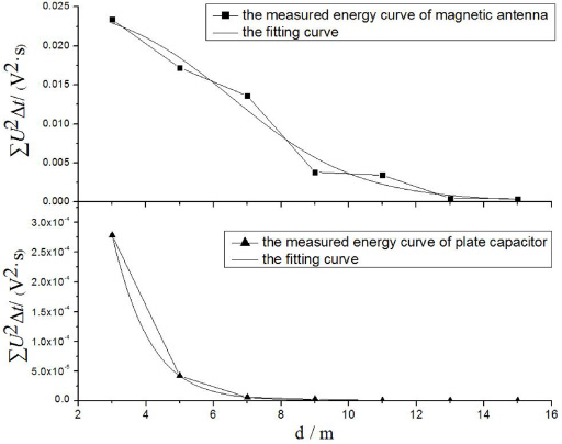
The tendency chart of the antenna coupling energy.
Figure 9 describes that the energy tendency chart of the magnetic antenna and the plate capacitance with distance further when the lightning current impulse is 9 kA. Where y-coordinate is the integral of antenna coupled lightning electromagnetic fields voltage square for time. It can be seen from the figure that, for the certain value of lightning current, when the distance is further, the energy of coupled plate capacitance is significantly weaker than that of the magnetic antenna.
We establish the simulated model of lightning channel in the laboratory to proceed the experiment of electromagnetic radiation. After analyzing the data and waveform received by the magnetic antenna and the plate capacitance, the following conclusions can be drawn.
After analyzing the voltage waveform of antenna coupling the lightning electromagnetic fields in 15 kA lightning current, we are verified that the energy of lightning current is mainly concentrated in the low-frequency stage, and the value-added decreases with the frequency increase. But it also has a certain proportion of the energy distribute in the high-frequency stage.
The waveform of plate capacitance appears before that of magnetic antenna. As the impulse current increases, the amplitude and energy of the antenna appear a holistic increasing trend. The growth of the magnetic antenna is more stable compared with the plate capacitance.
Radiant intensity is inversely proportional with the distance from the antenna to the current source. The amplitude and energy of the antenna present a tendency that the forepart is steep and the back is flat, and the plate capacitance is weaker changes than the magnetic antenna.