
Abstract
Electromagnetic forming (EMF) technology uses pulsed current to generate a pulsed electromagnetic force on metal workpiece to accomplish plastic deformation. It is a promising solution for the room temperature processing of lightweight alloy. Coil design is important to energy efficiency and forming performance of EMF. In order to clarify the effect of the equivalent radius of the drive coil on the forming performance, a simulation study is conducted. The preliminary experiment results show good agreement with results of the simulation, and prove the reliability of the simulation model. Then the process of the electromagnetic sheet free bulging is simulated and analyzed. It is found that the combined action of the boundary constraint and the inertia effect will influence the maximum forming depth. And the maximum values can be obtained at different systems when the ratio of the equivalent coil radius to the active workpiece radius is about 0.68.
Introduction
Electromagnetic forming (EMF) is a technology that employs the electromagnetic force to accomplish deformation of the metal workpiece [1,2]. It is reported that EMF can effectively eliminate residual stress, reduce spring-back, and improve the forming limit and surface quality of workpiece [3–5]. As a promising solution for the room temperature processing of lightweight alloy, EMF draws more attentions in the current energy and environment situation.
EMF is a complex multi-field coupling process involving electromagnetic field, structural field and thermal field. Analysis of the forming process is of guiding significance to explore EMF mechanism, optimize process parameters and improve the forming performance [6]. Early researchers studied the electromagnetic forming process analytically by equivalent circuit and equivalent magnetic circuit [7,8]. However, as the process is complicated and the model is idealized, the scope of application is limited and the accuracy of the solution is low. With the popularity of the commercial software such as COMSOL, MAXWELL and ANSYS, researchers can perform finite element analysis on the process of EMF which is difficult in the conventional analytical and experimental methods. The finite element methods mainly include loosely coupled analysis [9,10] and fully coupled analysis [11,12]. The loosely coupled analysis is based on the solution of different fields sequentially. The influence of deformation on spatial magnetic field is not considered. Therefore, this method is not suitable for the analysis of large deformation. Fully coupled analysis considers the dynamic interaction between different fields and the dynamic process of electromagnetic forming can be simulated and explored completely [13–15].
Process parameters are significant to the forming process and result. Many scholars conducted the researches on the discharge parameters such as discharge energy, discharge current frequency and discharge current pulse width. However, few researchers paid attentions to the structural parameters of drive coil [16–18]. The structural parameters of drive coil have an obvious effect on the distribution of electromagnetic force and affect the forming result directly. It is important to clarify the effect of the structural parameters of drive coil on the EMF process for the design of EMF system.
In this paper, the effect of the radius of drive coil on the maximum forming depth of the electromagnetic sheet during free bulging process is studied. For this purpose, a simulation model is constructed first and a series of preliminary experiments are carried out to check the validity and the accuracy of the proposed model. Based on the simulation model, the bulging process of the electromagnetic sheet is analyzed and then the effect of the equivalent radius on the maximum forming depth is studied.
Simulation model and experimental setup
Basic principle
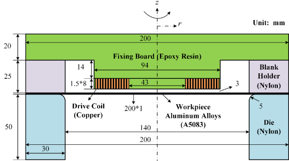
In an EMF process, the alternating current flowing through the drive coil excites a varying magnetic field around and the magnetic field will induce current in the metal sheet near the coil. Based on Faraday’s electromagnetic induction law, the interaction between the magnetic field and the induced current exerts magnetic pressure on the sheet and drives the workpiece to deform. The schematic diagram of the electromagnetic sheet free bulging system is shown in Fig. 1.
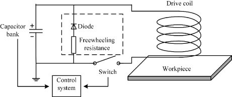
The schematic diagram of the electromagnetic sheet free bulging system.
As the electromagnetic sheet bulging system is axial symmetric, a two-dimensional axisymmetric model is built with COMSOL to simulate the forming process. As shown in Fig. 2, the model consists of drive coil, workpiece and air. The coil has 13 layers in the radial direction and only 1 turn in the axial direction. It is wounded by the copper wire with a cross section of 1.5 mm × 8 mm. And the inner and outer radii of the coil are 21.5 mm and 47 mm, respectively. The workpiece is a metal sheet with the radius of 100 mm. It has a fixed constraint in the peripheral area between the radii of 70 mm to 100 mm, which keeps still while other area deforms during the bulging. And the space between coil and workpiece is 3 mm.
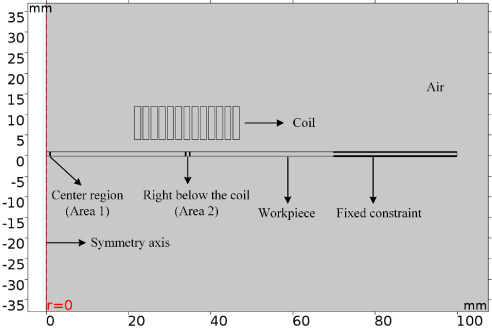
Two-dimensional axisymmetric simulation model.
The material of workpiece is aluminum alloy A5083. Based on our previous research, the flow stress in simulation with quasi-static constitutive model is closer to the actual situation [19], so the quasi-static stress-strain curve is employed in this study. The experimental and fitting stress-strain curves of aluminum alloy A5083 are depicted in Fig. 3. The expression of the fitting stress-strain curve is σ = 117.2e 0.3889.
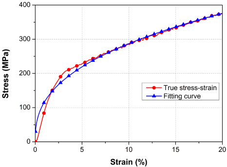
Stress–strain curve of the workpiece material.
The simulation model is a fully coupled finite element model. As the forming process is fast, the temperature rise in EMF is relatively small and the influence on the resistivity and forming depth is not obvious [20]. The temperature rise is ignored in this analysis. The simulation mainly includes circuit equations, electromagnetic field and solid mechanics. The simulation flow chart is shown in Fig. 4. Firstly, KCL and KVL equations are established according to the discharge circuit. And differential equations are given as
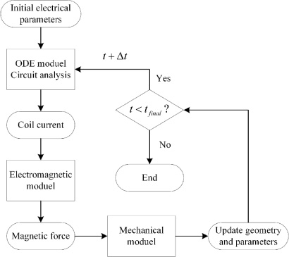
Simulation flow chart.
Once the capacitance and the initial voltage of the capacitor are given, the discharging current of the coil can be obtained by solving the above differential equations and the magnetic field distribution and the eddy current in the workpiece can be calculated based on the Maxwell’s equations. Due to the electromagnetic interaction, the electromagnetic force on the workpiece is calculated with the electromagnetic module. Finally, the solid mechanics module is employed to deduce the deformation and motion of the workpiece according to the electromagnetic force. With the above results for one time step (Δt), the sheet deforms and the process parameters are updated. The next time step will be started for cycles using the new parameters until the set time (t final ) is reached.
Discharge circuit parameters
Detailed structure of the experimental setup.
The experimental system is set up according to the schematic diagram as shown in Fig. 1. The structural parameters of the coil and the circuit parameters are the same as those in simulation of Section 2.2. The assembly of the drive coil and workpiece is shown in Fig. 5 and the external device and the assembly drawing of experimental setup in shown in Fig. 6. The workpiece is placed on the bottom die, which is a hollow cylinder with chamfer. And a blank holder with the thicknesses of 25 mm is placed on the workpiece. The drive coil is embedded at the bottom of an inverted convex fixing board. During the electromagnetic bulging, the coil is initially elevated 3 mm from the sheet as the board is put on the blank holder.
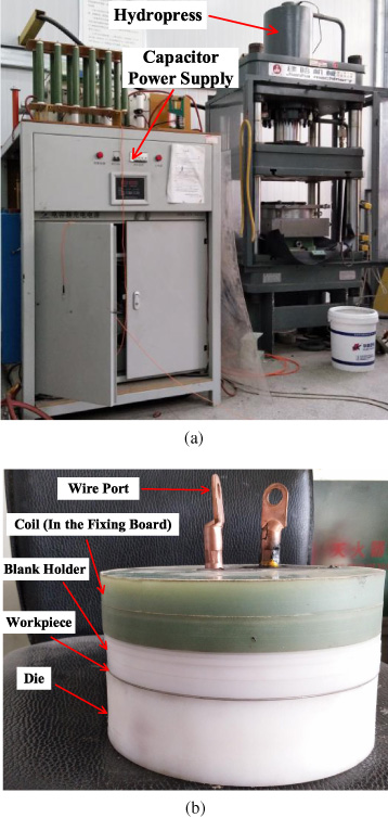
The photos of experimental setup. (a) Capacitor power supply and hydropress. (b) The assembly drawing of experimental setup.
Experiment results
With the above facility, a series of electromagnetic sheet free bulging experiments are carried out in different discharging voltage and the results are compared with the simulation results of the same parameters to verify the reliability of the simulation.
Two types of aluminum sheet with the thickness of 1 mm and 2 mm are employed in the experiments. The dependence of the maximum forming depth on the discharging voltage is shown in Fig. 7. The curves indicate that the maximum forming depth increases with the increase of discharging voltage nearly linearly before the workpiece breaks. The simulation results are in good agreement with the experiment results especially when the discharging voltage is not too high. For the 1 mm workpiece, the experiment forming depth is slightly shallower than the simulation one when the discharging voltage is lower than 5000 V. And when the voltage is higher than 5000 V, the experiment depth is slightly deeper than the simulation one. The simulation deviation at 6000 V and 7000 V are −6.77% and −7.60% respectively. For the 2 mm workpiece, the experiment forming depth is slightly shallower than the simulation one when the discharging voltage is lower than 6000 V. At the voltage of 7000 V, the experiment result is a little larger than the simulation one, and the simulation deviation is −5.78%. Above all, the simulation model in this paper is reliable and can provide effective analysis for the subsequent research.
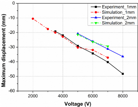
Experiment and simulation results of the electromagnetic sheet free bulging.
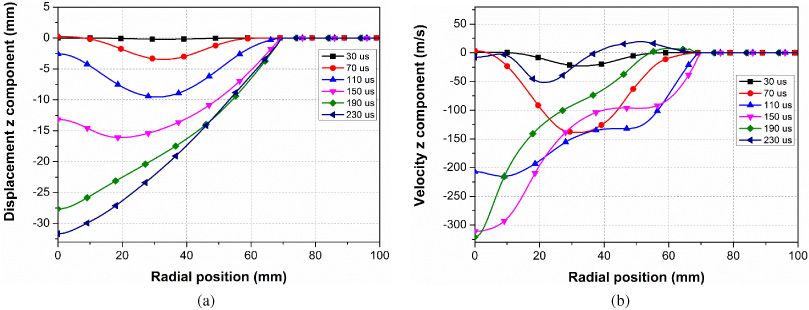
Displacement and velocity at chosen moments. (a) Displacement z component. (b) Velocity z component.
In this section, the forming process of the electromagnetic sheet free bulging is studied with the simulation model. The coil parameters of the simulation here are consistent with those mentioned above, and the discharge voltage is set at 6000 V. The displacement and velocity and during the deformation is first analyzed. The curves of the z component of the displacement and the velocity at chosen moments along the radial direction are shown in Fig. 8. The area under the coil winding deforms first, and the central area deforms later. However, the central area can get a higher speed and achieve a deeper forming depth. It could be seen that the motion of the two areas is distinguishing. In order to further explore the process of the electromagnetic sheet free bulging, two areas of the workpiece are selected for comparative analysis. In the following, Area 1 refers to the central area in the workpiece with the radius of 1 mm, and Area 2 refers to the area right under the coil winding in the workpiece with the thickness of 1 mm.
Then the current density, velocity z component, strain rate r component of the Area 1 and 2 are studied contrastively. According to the current curve of Fig. 9, the eddy current in the Area 1 and Area 2 is pulse and changes with the current of the drive coil. The amplitude of the average current density in Area 1 is −1.76 × 10⁸ A∕m2, while the amplitude in Area 2 is −4.07 × 10⁹ A∕m2. Combined the eddy current with the magnetic flux density, the distribution of the electromagnetic force along the radial direction can be obtained. As shown in Fig. 10, the electromagnetic force acting on Area 2 are much higher than that of Area 1. So, this area deforms first during the bulging. The main reason for the deformation of the Area 1 may be that it is driven by the surrounding region and deforms with the effect of inertia at high speed.
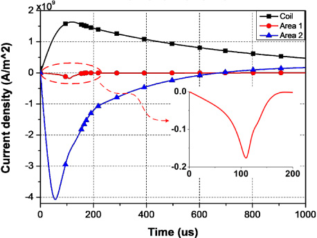
Current density of Area 1 and Area 2.
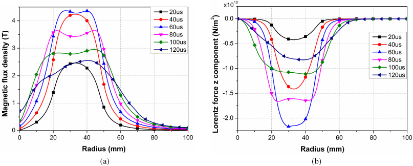
Magnetic flux density and electromagnetic force at chosen moments. (a) Magnetic flux density. (b) Electromagnetic force.
It can be seen from Fig. 11(a) that the maximum velocity of Area 2 is 130 m/s at about 97 μs, and the maximum velocity of Area 1 is 334 m/s at about 186 μs. Area 2 subjected to a larger forming force and reached the maximum velocity at an earlier time. However, the maximum velocity of Area 1 is much lower than that of Area 2. It is concluded that the velocity is limited as it is much closer to the restrained boundary. For Area 1, the acting force is quite small. The area is deformed due to the driving of the surrounding stretching and inertia effect. As the influence of the fixed constraint is smaller, the larger deformation and velocity can be achieved.
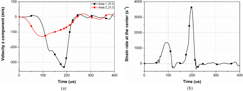
Velocity z component and strain rate r component. (a) Velocity curve of Area 1 and Area 2. (b) Strain rate curve of Area 1.
The strain rate curve of the Area 1 is shown in Fig. 11(b). From the figure, there are two distinct peaks of the r component of the strain rate. The first peak of strain rate r component curve is 1368 s−1 at about 92 μs when the velocity of Area 2 is closed to the maximum. It is probably mainly caused by the surrounding stretching rather than the electromagnetic force. The second peak is 3654 s−1 at about 197 μs when the eddy current decays to a low density as shown in Fig. 9. It may be due to the action of the inertia. As the value of the second peak is much higher than the first one and the electromagnetic force decrease rapidly during this time, the inertia effect is the determinant of the maximum forming depth.
The effect of the coil radius is studied based on the simulation model here. In order to reduce the influence of the size of the workpiece, radius ratio is employed. It is defined as the ratio of the equivalent radius of the coil to the active radius of workpiece. The equivalent radius of the coil is the average value of the inner radius and outer radius. And the active workpiece radius refers to the radius of the area that is not subjected to fixed constraint.
With the simulation model mentioned above, the basic parameters of the electromagnetic sheet free bulging keep unchanged except the inner radius (the outer radius is changed with the inner radius as the turns and layers of the coil remain the same). And the study is conducted with different inner radii. The maximum forming depth under different inner radii is shown in Fig. 12. It could be found that the maximum forming depth of the free bulging has a maximum value when the radius ratio is about 0.68. When the radius ratio is smaller than the optimum radius, the maximum depth increases with the increase of radius ratio, and the maximum depth decreases with the increase of the radius ratio when the radius ration is larger than the optimum radius.
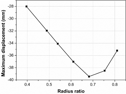
Forming depth varies with radius ratio.
In order to clarify the influence of the radius ratio, the velocity and strain rate under different inner radii of 15 mm, 25 mm, 35 mm and 44 mm are shown in Fig. 13. The corresponding radius ratios are 0.40, 0.54, 0.68 and 0.81, respectively.
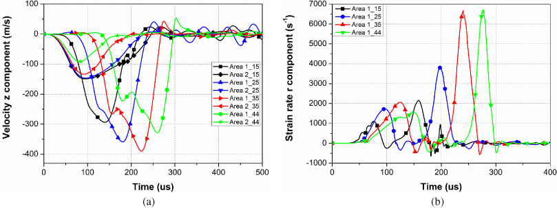
Curves under different coil radii. (a) Velocity z component. (b) Strain rate r component.
From the figure, the general trends of the velocity and strain rate under different inner coil radii are consistent with what is analyzed above. With the increase of radius ratio, the time difference of the peak velocities between the Area 1 and 2 increases. As the larger the radius becomes, the farther the first deformed region is from the center and the longer time the center deformation lags. With the increase of radius ratio, the maximum velocity of Area 2 tends to decrease as the fixed constraint has a greater influence. For the velocity of the Area 1, the maximum velocity increases first and then decreases with the increase of the radius ratio. The increase is due to the increase of the distance between the Area 1 and 2, which is beneficial for the Area 1 to get more action of the inertial force. And the reason for the later decrease is that the restriction of fixed constraint on the Area 2 is becoming more and more obvious, and it is difficult for the Area 2 to obtain sufficient velocity to drive the deformation. From the above, when the radius ratio is appropriate, the central area of the workpiece can obtain a higher velocity and a deeper depth under the balance of the boundary constraint and the inertia effect.
In order to obtain the universal optimum radius ratio, a series of simulations are conducted with different structure parameters. As listed in the Table 2, different influence factors are considered. For the Coil 1 and Coil 2, the axial turns are different while the other parameters keep unchanged. The effect of the radial layers is studied with the Coil 2 and Coil 3. The structural parameters of the Coil 3 and Coil 4 are the same, but the active radii of the workpiece are 70 mm and 100 mm, respectively. For the Coil 5 and Coil 6, the structural parameters of the bulging system are in full accord with different discharging voltages. For the Coil 7, the thickness of workpiece increases with other parameters kept the same as Coil 6. In addition, the wire size of the Coil 5–7 is different from Coil 1–4. The simulation results are shown in Fig. 14.
Five different structural parameters
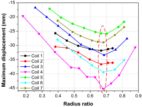
The influence of radius ratio for different structure parameters.
The simulation results indicate that the maximum forming depth of the workpiece increases first and then decreases with the increase of radius ratio for all coils. Furthermore, there is a universal optimum radius ratio of about 0.68, which makes the deepest forming under the same conditions. The optimum radius ratio is not affected by the axial turns and radial layers of the coil, wire size of the winding, the active radius of the workpiece or the discharge voltage.
A simulation of the electromagnetic sheet free bulging is developed to study the effect of the radius of the drive coil on the forming depth. Based on the analysis, it is found that the central area of the workpiece subjected to a small electromagnetic force has a maximum forming depth, and it is mainly depended on the inertia effect. The maximum value of the maximum forming depth can be obtained when the ratio of coil equivalent radius to workpiece active radius is about 0.68. The universal optimum radius ratio is the result of the combined action of the boundary constraint and the inertia effect. It is not affected by the process parameters and instructive for the design of the drive coil.
Footnotes
Acknowledgements
This work is supported by the National Natural Science Foundation of China (51607152) and the Presidential Fund of the Xiamen University (20720180079).