
Abstract
To improve output torque ability and reduce torque ripple in traditional synchronous reluctance motor (TSynRM), a new synchronous reluctance motor (NSynRM) is proposed in this paper. The rotor of NSynRM is composed of both grain-oriented silicon steel and non-oriented silicon steel. With the reasonable design of rotor structure, the torque of NSynRM has been improved and its torque ripple has been reduced greatly. Firstly, TSynRM and NSynRM are qualitatively compared by using the magnetic network method. Secondly, the main parameters of these two machines are optimized by using finite element method (FEM). Then the performance comparison between two optimized machines are carried out. Finally, the equivalent stress of these two machines at the maximum speed are analyzed. It can be seen that NSynRM can have 6.8% higher torque under rated load, 8% higher torque under maximum load, 17.5% wider constant torque operation region, and lower torque ripple compared with the TSynRM.
Keywords
Introduction
By using high co-energy permanent magnet (PM) to produce the magnetic field, PM machine can have the benefits of high output torque ability, high efficiency and high power density, thus the PM machines have been widely used for different energy conversion appliances [1–4]. However the material cost of rare earth PM is very high, which makes the cost of PM machine is high In addition the PM machine cannot avoid irreversible demagnetization risk. Thus synchronous reluctance machine (SynRM) without using the PM have drawn a great of attention in the past years [5–7].
The stator of SynRM is the same as that of traditional induction machine and synchronous machine, the rotor of SynRM is designed with multilayer magnetic barrier and thus the high saliency ratio can be resulted and the reluctance torque can be produced. The SynRM has the advantages of simple structure, low rotor loss, good mechanical robust and low cost, it also with the disadvantages of low torque density and power factor when compared with the PM machine.
The stator structure and winding configuration of SynRM are almost fixed, and the performance improvement of this kind of machine depends on using new optimized rotor structure. In [8], a form blocked rotor structure is proposed for SynRM, the experiment results show that this new structure can improve the rotor robustness and the maximum speed of the machine has been increased without reducing its magnetic performance. In [9], a new so-called Machaon rotor structure is proposed for the SynRM, the center symmetric line of the rotor barrier for each pole is kept unchanged, however the angle for the barrier in different poles can be changed, thus the torque ripple can be reduced by optimizing this angle.
There are two different kind of silicon steels can be used for building the rotor of SynRM, one is the non-oriented silicon steel sheets and another one is the grain oriented steel sheets. The permeability of non-oriented silicon steels sheets in all directions are same. For the grain oriented silicon steel sheets, its permeability along the rolling direction is very high and its core loss along this direction is very low, while for the other directions its magnetic characteristic is quite bad. In [10], a new rotor for SynRM is proposed, each pole of rotor core are made by the grain oriented silicon steel sheet stacked with its rolling direction along the d-axis direction and the shear direction along the axial direction. The experiment results show that the saliency ratio and the torque ability of this machine is very high, however this structure is very complex and the mechanical robustness is not good. In [11], a flux switching permanent magnet machine with grain oriented steel cores is proposed, the simulation results show that its torque has been improved 20% higher than that of the traditional flux switching machine.
A new synchronous reluctance machine (NSynRM) is proposed in this paper, it is designed with the grain oriented steel sheets inserted into the part of magnetic barrier of rotor core, where the rolling direction of the grain oriented steel sheets are along the d-axis direction and the stacking direction of that are along the q-axis direction, thus the saliency ratio of this machine has been improved. By using the finite element method (FEM), the torque, torque ripple, power factor, efficiency of NSynRM and TSynRM have been both optimized, and the performance between these two machines are compared, it shows that both the saliency ratio, torque ability, power factor, efficiency of the new machine has been improved greatly. The main design parameters of the proposed machines are shown in Table 1.
Main parameters of TSynRM and NSynRM
Main parameters of TSynRM and NSynRM
Rotor structure model
The torque of SynRM can be expressed by,
Figure 2 shows the magnetic flux line of the SynRM excited by the d-axis current excitation. As shown, the magnetic flux line is along the stator, air gap and rotor to form a closed loop. The magnetic potential at the different position of magnetic barrier is different, thus the magnetic flux will follow the magnetic bridge where the magnetic resistance is minimum and then the air gap and back to the stator teeth and stator yoke to form a closed loop. The d-axis magnetic circuit model and equivalent magnetic circuit model for the TSynRM and NSynRM are shown in Fig. 3, considering that the magnetic circuit is symmetrical and thus the magnetic circuit under one magnetic pole needs to be analyzed.

Rotor structure of SynRM, (a) TSynRM, (b) and (c) NSynRM.

Distribution diagram of magnetic flux lines of SynRM with d-axis current excitation.
In Fig. 3, F
d
is the magneto motive force produced by the d-axis current, R
e
the magnetic resistance for the stator yoke, R
c
the magnetic resistance for the stator teeth, R
a
the magnetic resistance for the air gap, R
r
the magnetic resistance for the magnetic bridge, and R
t
the magnetic resistance for the grain oriented silicon steel along the rolling direction. φ1, φ2, φ3, φ
N1, φ
N2, φ
N3 are the magnetic flux through the different magnetic bridge in two machine, as shown in Fig. 3, and they can be expressed by,
As magnetic resistance for the stator part is much lower than that of the air gap, thus R
e
, and R
t
can be regarded as 0 and above equations can be calculated by,

d-axis magnetic circuit model and d-axis equivalent magnetic circuit, (a) and (c) for TSynRM, (b) and (d) for NSynRM.
Figure 4 shows the magnetic flux line of the SynRM excited by the q-axis current, it can be seen the magnetic flux line follows along the stator, air gap and rotor to form a closed loop. The magneto motive force at the two side of the magnetic barrier is the same with the q-axis current excitation, and the magnetic flux can only enter the magnetic barrier in the rotor core. As shown in Fig. 2 and Fig. 4, the d-axis magnetic flux can reach to 0.055 Wb/m, while the q-axis magnetic flux can reach to 0.049 Wb/m.

Distribution diagram of magnetic flux lines of SynRM with q-axis excitation.
Figure 5 shows the q-axis magnetic circuit and q-axis equivalent magnetic circuit of the machine. As the thickness of magnetic separation bridge is very small and the magnetic flux leakage makes it to reach the saturation state, thus F q3 can be regarded as opened, and when the magnetic separation bridge is saturated then the magnetic flux through this part will be constant thus the magnetic flux source Φ b can be used in the equivalent magnetic circuit model.
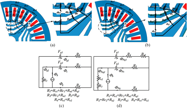
q-axis magnetic circuit model and q-axis equivalent magnetic circuit (a) and (c) for TSynRM, (b) and (d) for NSynRM.
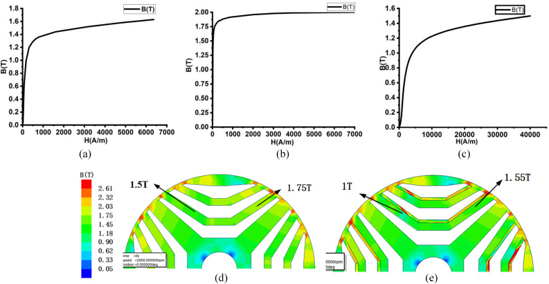
Flux density map of rotor fed by 20 A/mm2 current density, (a) B-H curve for non-grain oriented silicon steel, (b) B-H curve for grain oriented silicon steel along the stacking direction, (c) B-H curve for grain oriented silicon steel along the shear direction, (d) flux density distribution of TSynRM, and (e) flux density distribution of NSynRM.
In Fig. 5, F
q
is the magneto motive force produced by the q-axis current and R
e
, R
c
, R
a
have the same meanings as those in the d-axis magnetic circuit model, R
q
the magnetic resistance for the magnetic barrier, and R
s
the magnetic resistance of the grain oriented steel sheets along the q-axis direction. φ
q1, φ
q2, φ
q3, φ
Nq1, φ
Nq2, φ
Nq3 are the magnetic flux across the magnetic barrier in two machines. For the q-axis magnetic circuit model, the magnetic resistance for the air magnetic barrier and grain oriented steel sheets along the stacking direction needs to be considered, and thus the R
e
, R
c
are regarded as the shorted. The following equations can be obtained,
Based on the magnetic circuit model, the difference between the TSynRM and NSynRM are compared in the qualitative way. It can be seen that with the adoption of grain oriented steel sheets, the Φ nd and L nd are increased while the Φ nq and L nq are decreased, thus the reluctance torque can be improved. Figure 6 shows the magnetic flux density distribution of these two machines with the excitation current density of 20 A/mm2.
Figure 6(a) shows the magnetization curve of the non-oriented silicon steel sheets, it can be seen that the kneel point of this material is about 1.4 T, and Fig. 6(b) and Fig. 6(c) shows the magnetization curve of the grain-oriented silicon steel sheets along the rolling direction and the stacking direction. Figure 6(d) and Fig. 6(e) shows the magnetic flux density distribution on the rotor core. It can be seen that the magnetic flux density in the magnetic bridge in the TSynRM is saturated and the maximum flux density is about 1.75 T. For the NSynRM, the magnetic flux density is about 1.5 T, and the flux density on the grain oriented silicon steel sheet is very high, which is resulted by high permeability characteristic of the used material. The magnetic separation bridge are both saturated for these two machines.
Design optimization for TSynRM
Figure 7 shows the main parameters for design optimization in the TSynRM. The rotor of TSynRM is made by only using the non-oriented silicon steels, S qi is the magnetic bridge width along the q-axis, W qi is the magnetic barrier width along the q-axis direction, 𝛼 is the angle between the first magnetic barrier and q-axis, and 𝛽 i is the magnetic barrier angle, where i means the layer number.
The ratio of the magnetic bridge to total rotor is defined by
As reported in [16], when K equals about 0.5–0.55, the torque can be maximized and the torque ripple can be minimized, when K < 0.5 then the SynRM will face heavy magnetic flux leakage issue and then the torque ability will be reduced, on the other hand when K > 0.55 then the magnetic bridge will be statured and the torque ripple will be increased. In this paper, S d = 52 mm, and when K = 0.5, then ∑ W qi = ∑ W si = 26 mm. The average torque and torque ripple against the variation of flux barrier end angles when 𝛽3 equals 2.5 deg, 3 deg, and 3.5 deg are illustrated in Fig. 8. It can be seen that the average torque increases with the increases of 𝛽1 and 𝛽3, the average torque increases first and then reduces with the increases of 𝛽2 and when it equals about 4.5 deg ∼ 5.5 the torque can be maximized. For torque ripple, it can be seen that the lower 𝛽1 the lower torque ripple, the higher 𝛽3 the higher torque ripple, and the torque ripple can be minimized when 𝛽2 equals about 5.5 deg to 6 deg. Comparing with the torque ripple, the variation of torque with the variation of flux barrier end angle is quite low. In this paper, 𝛽1 = 4 deg, 𝛽2 = 6 deg, 𝛽3 = 2.5 deg is picked for the TSynRM design, and then its torque is 215 Nm, and its torque ripple is 7.2%.
Rotor structure of TSynRM.

Torque characteristics of TSynRM with different flux barrier end angles, (a) (b) and (c) torque, (d) (e) and (f) torque ripple.
Figure 9 shows the average torque and torque ripple against the magnetic barrier width variation, as K is set as 0.5, thus when W q1 and W q2 are determined, W q3 will be determined as well. As shown, when W q1 increases the torque decreases while the torque ripple decreases first then it will increases and the minimum torque ripple can be achieved. As for W q2, when it increases torque will increase first and then decrease and the torque ripple will decrease first and then increase. Therefore, W q1 = W q2 = 8 mm and W q3 = 10 mm is determined for the machine design, then its torque is about 216 Nm and its torque ripple is about 7.9%. It can be seen that when the magnetic barrier width in the different layers are different then the good performance can be achieved [17,18]
Torque characteristics of TSynRM with different flux barrier width, (a) torque and (b) torque ripple.
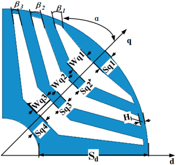
For the electrical machine design, the optimization is essential and it needs to be optimized under the determined control method [19,20]. NSynRM share the same stator and winding configuration with TSynRM, the main difference are the rotor is made by using both the non oriented silicon steel and grain oriented silicon steel. In Fig. 10, the meanings of W qi , 𝛼, 𝛽 i are the same as those shown in Fig. 7, and S qi , L qi are the width of magnetic bridge made by non oriented silicon steel and grain oriented silicon steel respectively, where i means the layer number. For NSynRM, K is determined as 0.5 as well.
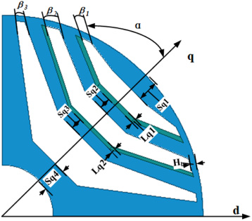
Rotor structure of NSynRM.
The average torque and torque ripple against the variation of magnetic barrier end angle are shown in Fig. 11. It can be seen that both the average torque and torque ripple increases with the increases of 𝛽1, when 𝛽2 equals 3.5 deg ∼ 4.5 deg the torque will be maximized and the torque ripple will be minimized, and when 𝛽3 increases the variation of torque is small however the torque ripple will be increased. As shown, the variation of torque with the variation of 𝛽 i is quite low, however the variation of torque ripple is very high. For the NSynRM, the 𝛽1 = 2.5 deg, 𝛽2 = 3.5 deg, 𝛽3 = 2.5 deg are determined, where its corresponding torque is 231Nm and torque ripple is 6.6%.
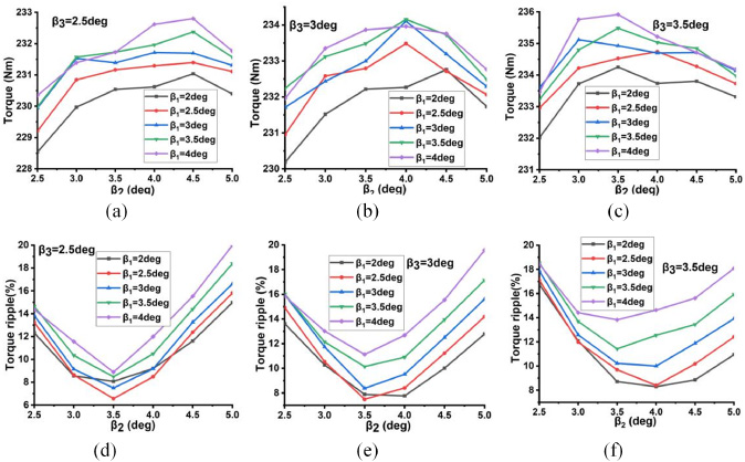
Torque characteristics of NSynRM with different flux barrier end angle, (a) (b) and (c) torque, (d) (e) and (f) torque ripple.
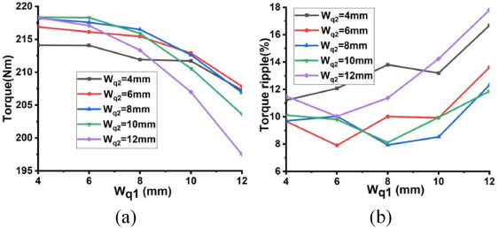
Figure 12 shows the average torque and torque ripple against the variation of magnetic barrier width. As shown, with the W q1 and W q2 increases, the torque increases first and then decreases. And the torque ripple main depends on the W q2, and when W q2 equals about 6.5 mm ∼ 8.5 mm, the torque ripple can be minimized. Finally, W q1 = 4.5 mm, W q2 = 6.5 mm, W q3 = 15 mm are determined, then its corresponding torque is about 231.8 Nm and torque ripple is about 6.8%. It can be seen that both W q1 and W q2 is quite low, as the grain oriented silicon steel sheets are existed in the first and second magnetic barrier as shown in Fig. 10.

Torque characteristics of NSynRM with different flux barrier width, (a) average torque and (b) torque ripple.
Figure 13 shows the torque increases and the torque ripple increases first and then decreases with the increases of L q1 and L q2, When L q1 equals about 1.6 mm ∼ 2.0 mm and L q2 equals about 1.3 mm ∼ 1.6 mm, then the minimum torque ripple can be achieved. Finally, L q1 = 1.6 mm and L q2 = 1.3 mm is determined, and then the torque is about 232 Nm and torque ripple is 6.9%.
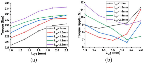
Torque characteristics of NSynRM with different oriented electrical steel width, (a) average torque and (b) torque ripple.
For the calculation of torque in above design the current density of 20 A/mm2 is adopted. It can be seen that when the grain-oriented silicon steel sheet is used then the torque of NSynRM has been increased about 6.8%, and the torque ripple has been reduced about 1%. The obtained main dimension for above two machines are tabulated in Table 2.
Optimized parameters of TSynRM and NSynRM
As shown in (1), high value of L d and low value of L q is required for SynRM, and saliency ratio is the key index which is defined by the L d divides L q . Figure 14 shows the calculated d-axis inductance and q-axis inductance with the variation of d-axis and q-axis current density in above two machines.
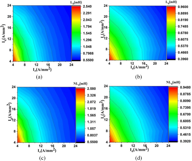
Inductance versus current diagram, (a) Ld for TSynRM, (b) Lq for TSynRM, (c) Ld for NSynRM, and (d) Lq for NSynRM.
It can be seen that with the d-axis current and q-axis current increases, both the d-axis inductance and q-axis inductance decreases. Compared with q-axis current, d-axis current plays a more important role, since when it is very low the d-axis magnetic circuit will not be saturated, and with the I d increases the d-axis magnetic circuit will saturate quickly and thus L d will be decreased quickly. Because of the cross saturation effect the L q decrease with the increases of I d . As some part of the q-axis magnetic circuit is the air, and the magnetic resistance of the air is very high, thus the q-axis inductance will not change greatly with the current increases. As shown, the L d in NSynRM is higher than that in TSynRM and the L q in NSynRM is lower than that in NSynRM, which is resulted by the adoption of grain oriented silicon steels.
Figure 15 shows the torque waveform and the torque with the variation of current density and current of these two SynRMs. In Fig. 15, CD and NCD means the current density for the TSynRM and NSynRM respectively, and the unit is A/mm2. It can be seen that for achieving maximum torque there is a determined current angle for the different current density. In SynRM, the optimal current angle is between 50 deg and 55 deg. As shown, NSynRM has higher torque ability especially when the current density is high. When current density is 16 A/mm2 the torque for TSynRM and NSynRM is 185.5 Nm, and 198.2 Nm respectively, and the torque increase rate is about 6.8%. When the current density is 24 A/mm2 the torque for TSynRM and NSynRM is 243.1 Nm, 262.6 Nm respectively and the torque increase rate is about 8%. The torque increase rate (T
k
) defined as,
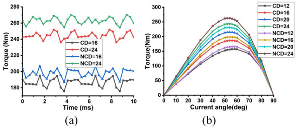
Torque versus current, (a) torque waveform, (b) torque versus current and current angle.
Figure 16 shows the power factor variation with the torque increases for these two machine. As the power factor is proportional to the saliency ratio, when the torque is low then the magnetic circuit along both the d-axis and q-axis is not saturated thus the power factor is high, however when the torque is high then the magnetic circuit will be saturated, then the power factor will be reduced. Compared with the TSynRM, the adoption of grain oriented silicon steels in the NSynRM releases the saturation problem, therefore its power factor is higher.
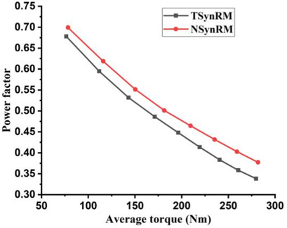
Power factor versus torque curve.
Figure 17 shows the efficiency map of TSynRM and NSynRM. In Fig. 17 the imaginary line means the operation line under the rated current density of 16 A/mm2. The rate speed is 4000 rpm, and torque decreases after the speed is over than 4000 rpm since for keeping the voltage not higher than the rated voltage the current needs to be reduced or the current angle needs to be increased. It can be seen that the main efficiency of these two machines are quite similar and the efficiency has reached to 87% in the constant torque region and for the constant power region the efficiency has reached to about 95%. As shown the constant torque operation region of the NSynRM machine is about 17.5% wider than that of the NSynRM.
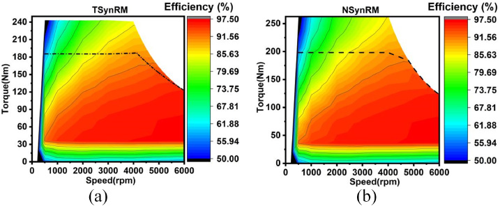
Efficiency map of (a) TSynRM and (b) NSynRM.
As the grain oriented silicon steel sheets have replaced some part of the non oriented silicon steel sheets in the NSynRM, thus the effective magnetic bridge width has been reduced from 5.5 mm to 4 mm and thus the mechanical stress has been increased. In this paper, the mechanical stress of two SynRMs are analyzed at the maximum speed of 6000 rpm. Figure 18 shows the stress distribution of these two SynRMs effected by both electromagnetic force and centrifugal force. As shown, the stress distribution are basically the same, and the maximum stress is appeared on the magnetic separation bridge. For NSynRM the maximum stress is higher and it is about 157 Mpa, and the maximum allowable tensile strength of the silicon steel sheet is about 305 MPa, which is still 2 times higher than the value of 157 Mpa. Therefore the NSynRM can still maintain the high mechanical strength when it operated at the maximum speed of 6000 rpm.
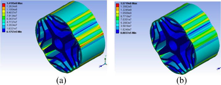
Equivalent stress analysis. (a) NSynRM. (b) TSynRM.
Based on the unique properties of grain oriented silicon steel sheets, a NSynRM is proposed in this paper. By using the FEM, the NSynRM and the benchmark TSynRM are both designed, optimized, analyzed and compared, some conclusions are obtained:
The magnetic barrier angle has a great influence on the torque ripple but low influence on the average torque; and the magnetic barrier thickness has a great influence on both the average torque and torque ripple. The saturation of magnetic bridge can be released by adding the grain-oriented silicon steels in the magnetic barrier with the rolling direction along the d-axis direction and the stacking direction along the q-axis direction. The maximum torque has been improved about 8%, the torque ripple has been reduced and the constant torque operation region has been improved about 17.5% in the NSynRM, as the adopted grain oriented silicon steel has very good electromagnetic performance in the rolling direction. For stress analysis at the maximum speed, these two SynRMs have the similar stress distribution and the maximum stress is appeared at the magnetic separation bridge, and both of them can be operated at the maximum speed.
Footnotes
Acknowledgements
This work was supported in part by the Natural Science Foundation of Hebei Province under Project E2019202220, in part by National Natural Science Foundation of China under Project 51877065, in part by Hebei Province Education Department Youth Talent Leading Project under grant BJ2018037, and in part by the State Key Laboratory of Reliability and Intelligence of Electrical Equipment under Grant EERIKF2018005.