




Abstract
Electromagnetic valve train (EMVT) can realize independent, real-time and continuous valve motion regulation through the precise motion servo control, which has great potential to improve the efficiency of internal combustion engines. As an electromechanical integration device, EMVT is driven by electric energy, and the loss distribution is complex and changeable under different service conditions. Especially when the EMVT is used in exhaust system, the high gas pressure after combustion will increase the energy loss and operating temperature significantly. In order to improve the device performance, this study analyses the loss distribution and variation law of EMVT under different service conditions. First, the flux density is obtained by the 3D finite element simulation. In combination with the valve train dynamic Matlab/Simulink model, the copper loss and iron loss of EMVT under typical conditions are explored in detail. Then, the influence of the motion parameters (transition time) and condition parameters (gas pressure) on EMVT’s loss are calculated and analyzed significantly. In the end, the accuracy of the loss models and analysis results is verified by the experiment based on linear load simulator.
Keywords
Introduction
With the rapid development and extensive application of the automobile industry, the energy crisis and environmental pollution problems have become increasingly serious. China’s crude oil consumption has reached 647 million tons in 2019 [1].
New energy-saving and environment-friendly technologies such as fuel cells [2,3], solar cells [4,5], lithium batteries [6,7] and other electric vehicle technologies [8–10] have become the important development direction of automobile industry in the future, but it will take a long time for these technologies to become widespread. At present, the internal combustion (IC) engine, as a traditional vehicle power source, still occupies a large market share. The researches on energy conservation and emission reduction of IC engine have a more practical significance. As one kind of fully variable valve technology, the EMVT has a large potential to improve the engine power, reduce the emissions and fuel consumption [11–13].
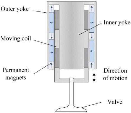
Schematic structure of the EMVT.
The electromagnetic linear actuator is the core executive component of EMVT [14], which belongs to electromechanical-magnetic integrated system and has a wide application in the industrial field nowadays [15,16], as shown in Fig. 1. Most of the electric power consumed by the electromagnetic linear actuator is converted to heat during its operation, which will raise the device temperature. Especially when EMVT is applied to exhaust system, the valve will face an in-cylinder gas pressure of 0.6 MPa or higher when opening [17], resulting in the energy consumption and temperature increase significantly. It not only affects the working stability and reliability of the EMVT, but also worsens the engine fuel economy. Therefore, it is essential for the EMVT performance improvement to clarify the energy loss distribution and variation law under different service conditions.
Current researches of motor losses mainly include copper loss, iron loss, mechanical loss and other losses [18,19]. Kuttler et al. developed an original and mathematical model which can provide fast and accurate estimation of iron loss based on the first harmonic hypothesis [20]. Yan et al. analyzed the influence of the control parameters on the iron loss of switched reluctance motor under different control modes [21]. Due to the particularity of structure, the loss distribution of EMVT is different from the conventional motors. Dai et al. [22] have studied the loss distribution law of the moving-coil electromagnetic linear actuator preliminarily, the mover remained locked and the effect of exhaust gas is neglected. In previous studies, the dynamic characteristics of EMVT under the conditions of different gas pressure have been discussed [23]. As a follow-up study, this paper will deeply analyze the loss distribution laws of EMVT under different service conditions. This would lay a foundation for the performance optimization and promotion of EMVT.
Be differ from the conventional valve train driven by cam, the EMVT converts electric power to mechanical energy in form of linear motion directly. This direct-drive mode brings a small frictional loss, so the mechanical loss of EMVT is relatively lower compared with that of cam valve train. Copper loss and iron loss dominate most of EMVT’s loss, as shown in below.
Iron loss is generated in the changing magnetic field, which can be calculated by means of loss segregation based on the Steinmetz equation [24], and its expression is as follows.
The mechanical loss W
mech
depends on the motion of moving coil, which can be shown as below.
When the EMVT is used to exhaust system, a large transient current is needed to overcome the gas pressure after combustion. Then the loss distribution is changed and the additional energy is consumed during the valve opening, as shown below.
3D finite element (FE) models of EMVT are carried out in the electromagnetic analysis software, which are used to calculate the flux density and iron distribution of actuator. Meanwhile, the dynamic Matlab/Simulink models of EMVT are established to obtain the valve motion and excitation current, and then the results are used as the excitation sources of FE simulation models.
3D FE models
As shown in Fig. 1, the EMVT consists of outer yoke, inner yoke, permanent magnets, moving coil and a valve. The distribution of permanent magnets is designed with Halbach array which could increase actuator’s internal magnetic field intensity and decrease its outer one [14]. In the simulation models, the materials of inner yoke and outer yoke are steel-1008 with strong permeability and low cost, while that of permanent magnets is common NdFe 45. In order to obtain a solution with the highest precision, the mesh density has been increased to achieve a better accuracy in regions with rapid spatial field variation. Tetrahedral automatic meshes have been used for throughout the model, with the mesh encrypted only around the air gap to reduce computation time [25,26]. The main structural parameters and electrical parameters of actuator are shown in Table 1. Figure 2 demonstrates both the FE model and the nephogram of static magnetic flux density of EMVT.
Parameters of actuator
Parameters of actuator
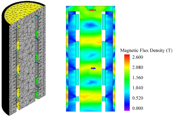
FE model and nephogram of static magnetic flux density of EMVT.
The curves of valve lift and excitation current are essentials for the calculation of dynamic flux density and iron loss distribution under different conditions. Because of this, the dynamic models of EMVT are established in Matlab/Simulink, which include mathematical module of EMVT, control algorithm module and gas pressure module, can be obtained in Fig. 3. The mathematical module of EMVT is carried out with the mechanical, electrical and magnetic subsystems. While the adaptive robust control (ARC) method is used to achieve the fully variable valve motion and improve the response velocity and control precision. The gas pressure is decided by the engine thermodynamic cycle and fed back to the mathematical module and ARC block. On this basis, the dynamic performance of EMVT can be calculated accurately.

Block diagram of dynamic model.
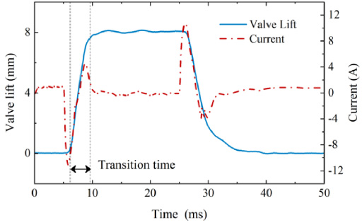
Valve lift and excitation current at a typical condition.
Previous research has been confirmed that the dynamic models of EMVT is accurate and efficient, the results could be coincided with the experimental data very well [23]. Then the controlled valve lift and coil current would be served as the excitation sources of the FE models. Figure 4 shows the excitation sources at a typical condition.
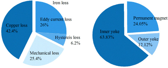
Proportion diagram of loss distribution of EMVT.
The analysis is carried out primarily at a typical condition of maximum lift as 8 mm, opening/closing transition time (the time valve moves from 5% to 95% of the travel) as 3 ms and no gas pressure disturbance, Fig. 5 illustrates the loss distribution of EMVT clearly. The total loss in one cycle is about 1.18 J, in which the copper loss takes a largest percentage about 42.4%. For the EMVT with fixed structural and electrical parameters, the copper loss mainly depends on the value of coil current. The coil current of EMVT can be optimized and decreased by innovative motion control method [27].
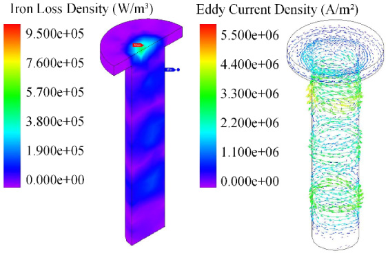
Nephogram of iron loss density and vector diagram of eddy current density of inner yoke.
The iron loss occupies a considerable percentage about 32.2% of total loss, relatively lower than copper loss, in which the eddy current loss takes a largest part. With further research, the distribution of EMVT’s iron loss in components is carried out, we can get that the iron loss in inner yoke is the highest. Figure 6 shows the nephogram of iron loss density and vector diagram of eddy current density of inner yoke. The high density area of iron loss mainly locates in the end of inner yoke, which is also related with the distribution of permanent magnets. Strong eddy currents are generated along the circumferential direction in inner yoke, and the density increases along with the radial direction gradually. In additional, the mechanical loss takes a smallest percentage about 25.4%, which can attribute to the direct drive mode.
Furthermore, we can find that the current consumption mainly occurred in the process of opening and closing motion based on the curves in Fig. 4, while the losses during the holding period only take a small part. The variable opening and closing motions of EMVT mean different loss distributions, which would be researched in below.
Transition time is an important parameter for the dynamic performance of EMVT, also the valve motion strategies with variable transition time are widely used in the camless engine [28]. Calculation and analysis of EMVT’s loss are carried out at three different conditions of valve opening/closing transition time as 3 ms, 4 ms and 5 ms.
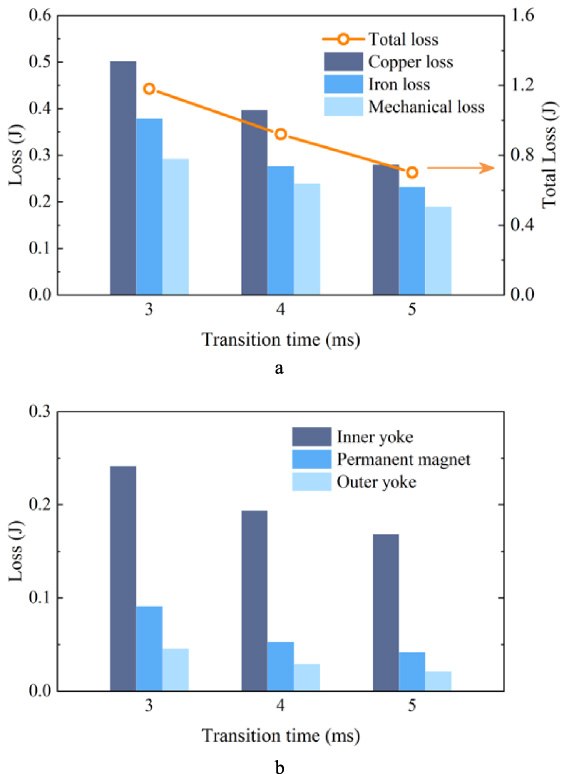
Loss distribution of EMVT under variable transition time. (a) Loss compositions of EMVT, (b) Iron loss in different components.
With the increase of transition time, the excitation current of EMVT decreases significantly, and then the copper loss, iron loss and mechanical loss have a reduction, as shown in Fig. 7(a). At the condition of transition time as 4 ms, the total losses per cycle have a decline about 22.9% compared with that of 3 ms. in which the copper loss has a decrease about 22% and the iron loss has a decrease about 27.1%. And at the condition of transition time as 5 ms, the total losses per cycle have a decline about 40.7% compared with that of 3 ms. in which the copper loss has a decrease about 44.3% and the iron loss has a decrease about 38.7%.
In additional, it can be found that almost every loss keeps an unchanged proportion at the conditions of variable transition time, and the changes of iron loss in different components also follow this rule as demonstrated in Fig. 7(b). Based on the theoretical analysis of loss, both the excitation current and excitation period are changed with different transition time, so the copper loss and iron loss are impacted significantly. Also a slow valve velocity means a small damping force, and then the mechanical loss has a decrease.
Valve opening motion is disturbed by cycle-to-cycle combustion gas force when the EMVT is used in exhaust system, previous study has revealed the formation and evolution mechanism of the gas pressure disturbance, as shown in Fig. 8 [23]. Now the loss distributions are researched at the conditions of initial gas pressure as 0.2, 0.3, 0.4 and 0.5 MPa, while the controlled valve motions are kept unchanged with the lift as 8 mm and transition time as 3 ms.
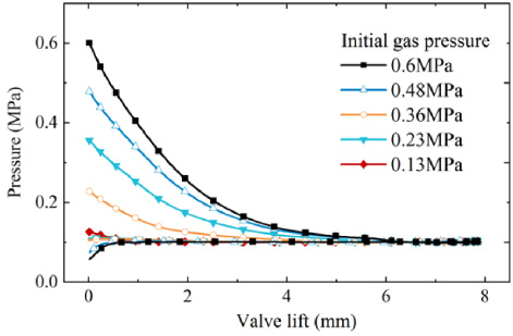
Curves of the gas pressure disturbance.
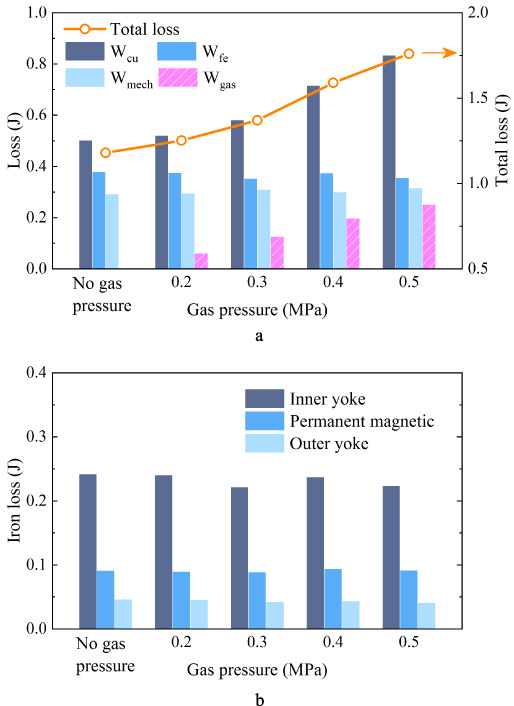
Loss distribution of EMVT under variable gas pressure. (a) Loss compositions of EMVT, (b) Iron loss in different components.
No doubt the gas pressure disturbance would increase the EMVT’s loss significantly, as shown in Fig. 9. At the condition of 0.5 MPa gas pressure, the total loss of EMVT reaches to 1.76 J per cycle, which has an increase of 49.2% compared with no gas pressure condition. While the loss increment mainly focuses on the copper loss and additional differential pressure loss, in which the copper loss increased by 0.33 J and differential pressure loss is about 0.25 J. By comparison, the iron loss and mechanical loss have no obvious changes, which mean that the proportion of EMVT’s loss composition is changed. The gas pressure disturbance causes an increase of excitation current, but the excitation period is well maintained with the ARC method. Also the internal magnetic flux density of actuator has no further risen with a larger current in consequence of magnetic saturation. Based on the above reasons, the iron loss has no prominently changes at the conditions of variable gas pressure disturbance. The results are also verified by the nephograms of magnetic flux density and iron loss density, not tired in words here.
The changing laws of EMVT’s losses under the conditions of variable transition time and gas pressure disturbance have been researched through the numerical simulation method, which need to be verified by the experiments. Due to the complexity and nonlinearity of the gas pressure disturbance, the test-bench based on linear load simulator is used to offer an actual and flexible load environment, which is shown in Fig. 10.
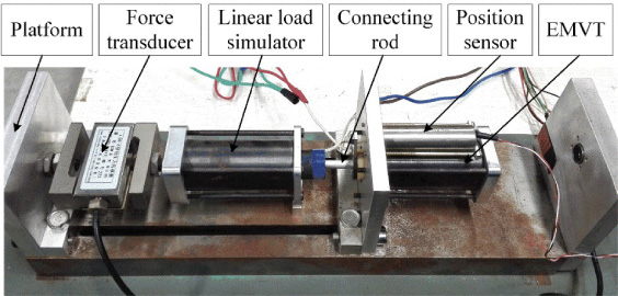
Test-bench based on linear load simulator.
Another electromagnetic linear actuator is used as a load simulator for simulating the engine combustion pressure conditions so as to reduce the risk of damaging engine test setup. Based on the e.g. (7), the gas force acting on EMVT can be produced by adjusting the coil current of simulator. A digital signal processor (TMS320f2812) with a clock frequency of 150 MHz is used as the digital controller. A position sensor (Schaevitz 500 LCIT) is mounted by the side of EMVT to provide the position feedback. Current sensors (TBC10SY) and voltage sensors (SMIV ± 50DCE) are used to measure the input current and voltage of EMVT.
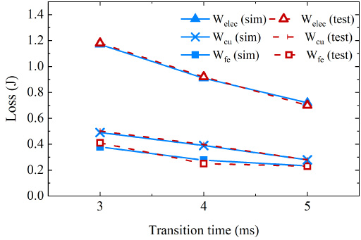
Loss comparison diagram of simulation and test under variable transition time.
Previous studies have proved the accuracy and reliability of this experimental method [23]. Based on this, the losses of EMVT are measured under different service conditions, but it is not feasible to test every loss composition directly. The input energy W elec can be carried out by the measured current and voltage, the copper loss W cu and mechanical loss W mech are calculated with the above equations (e.g. (2) and e.g. (4)). As a consequence, the iron loss W fe can be obtained indirectly based on the law of energy conservation. Figure 11 shows the experimental results of EMVT’s losses under variable transition time, the maximum difference between simulation and test is about 7.6%. These prove the accuracy and reliability of the simulation models, and we can get the conclusion that valve motion with faster transition time would increase the loss of EMVT, but the proportion of different loss composition keeps unchanged basically.
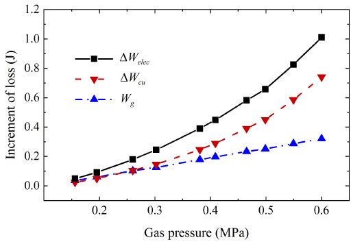
Increment of EMVT’s loss under variable gas pressure.
For further investigates, losses are measured under the conditions of initial gas pressure from 0.1 to 0.6 MPa. Through calculation, the increment of the total loss, copper loss and differential pressure loss are demonstrated in Fig. 12. The increment of the total loss of EMVT caused by gas pressure disturbance can be considered as the sum of differential pressure loss and the increment of copper loss approximately, which is shown as below.
This paper mainly studies the effect of the motion parameters (transition time) and condition parameters (gas pressure) on EMVT’s loss. On this basis, the loss distribution laws of EMVT under different service conditions are summarized. Main results are shown below. With the simulation modeling of EMVT and analysis on its loss composition, the copper loss takes a largest proportion, the iron loss takes a second place and the mechanical loss takes a smallest proportion. Meanwhile, the iron loss in inner yoke among all the components accounts for more than 63.8%. Valve motion with faster transition time would increase the EMVT’s loss significantly, but the proportion of different loss composition keeps unchanged basically. The changes of iron loss in different components also follow this rule. The gas pressure disturbance would increase the EMVT’s loss obviously, the loss increment mainly focuses on the copper loss and differential pressure loss, the iron loss and mechanical loss have no prominent changes.
Loss analysis of EMVT under different service conditions contributes to the improvement of EMVT’s performance. Further works are being purposed to optimize the mechanical structure and magnetic topology.
Footnotes
Acknowledgements
This work was supported by the Natural Science Foundation of Jiangsu Province, China [grant number BK20190972]; National Natural Science Foundation of China [grant number 51905319]; China Postdoctoral Science Foundation [grant number 2020M681845] and Foundation of key Laboratory of Equipment Preresearch [grant number 6142212190410].