
Abstract
Nowadays, several applications of electroporation have been adopted in cancer therapy with promising results that have boosted research interest. To develop new treatment options, the development of electroporation models and measurement method in order to study the real distribution of the electric field potential are needed. Nowadays, current trends in electroporation techniques suggest the use of more powerful pulse generators that enables the treatment of larger tissue volumes. However, new challenges arise regarding the modeling of the electroporation process in large tissue volumes as well as the potential thermal effects when large amounts of energy are used. The aim of this paper is to propose a finite element analysis (FEA) based model using COMSOL of the irreversible electroporation process considering both electrical and thermal effects, and to validate it through in-vivo experimentation. Moreover, we propose a methodology for measuring the electrical potential in different points of a biological tissue during the application of a train of pulses to measure the distribution of the electric field inside the tissue. For this application, needle-based electrodes have been developed to achieve the least invasive measurement possible. These tools are aimed to improve the application of the electroporation treatment by reducing its side effects.
Introduction
Electroporation is based on the change in the permeability of the cell membrane by means of the application of an electric field. There are mainly two types: reversible electroporation, which is commonly used to improve the cell absorption of certain drugs, and irreversible electroporation (IRE), where the applied field is larger, and the damage becomes irreversible.
Although IRE currently is being used in many contexts, including industrial applications for food processing and/or sterilization, this paper will focus on IRE as one of the most promising therapies for cancer treatment. Although it is a relatively new technique [1], a significant number of tests have already been performed.
In the field of medicine, one of the challenges of IRE is that the required electric fields to ensure an adequate treatment can easily lead to tissue overheating. Overheating the tissue reduces IRE advantages over traditional ablation treatments, and it could be dangerous for the patient. For these reasons, and despite its promising results, further research on the applied electric field intensity and an adequate modeling of its thermal behavior are required.
IRE usually requires of extensive experimentation to optimize the process and maximize the desired cell destruction with minimum collateral damage. Besides, unlike purely thermal treatments like radiofrequency or microwave ablation [2], it requires in-vivo experiment to assess its biological effects [3]. This leads to a complex optimization process and makes the development of accurate models necessary. Currently, there are several models that study the different effects of IRE in multiple biological tissues. However, these models study only a few unrelated effects: electric models [4], poration models [5,6], impact models [7], thermal simulation [8], and others. Besides, when large tissue ablations are considered, it is required to include both thermal and electric effects in the model. Also, in this field, to achieve a homogeneous ablation it is necessary an adequate distribution of the electric field. Due to the complexity of the biological tissues, it is important to find tools that allow to verify and to study the influence of the involved phenomena. Moreover, recent research trends have proposed new generators [9] able to treat larger volumes of tissue, making more important a deep study of the electric field distribution to ensure proper treatment [10,11].
To design the power electronic converters, as well as to optimize the IRE pulse delivery, an equivalent model that replicates the electrical behavior of the tissue under treatment has been obtained. Several models have been proposed in the past to study the distribution of the applied electric field [12]. These field distribution models usually need large amount of validation and adjustment data. Therefore, measurement methods are necessary to correlate the electric field distributions.
The electrical signals involved in the treatment can be analyzed by circuit models composed of lumped elements [13]. The objective of these models is to study the change of the current during the treatment as a function of different variables. With these models it is possible to analyze the power necessary to treat a tumor and even to study the effectiveness of the treatment according to the change of the impedance [4].
As a non-thermal treatment, it is necessary to ensure that no overheating injuries occur. Therefore, the temperature must be monitored to avoid any thermal damage during the treatment. Currently, there are thermal models that reproduce radiofrequency treatments and interaction between the electrical and the thermal parts in this treatment is very similar to that in IRE [14].
The aim of this paper is to propose one finite element analysis (FEA) based model of the irreversible electroporation process considering both electrical and thermal effects. To achieve this objective, the electric field distribution will be measured as a starting point for the proposed model. The accuracy of the proposed models are verified by comparing with experimental results during in-vivo IRE experiments [15].
The remainder of this paper is organized as follows. Section 2 details the proposed multi-physics models including both electrical and thermal effects. In Section 3, the main simulation and experimental results proving the feasibility of this proposal are included. Finally, the conclusions of this paper are drawn in Section 4.
Proposed multi-physics models
Description
Two different models have been developed. First proposed FEA model is based on a 2D geometry with symmetry of revolution. The geometry is composed of a sphere of air. Inside, two cylindrical steel electrodes are found. Between the two electrodes a geometry representing the tissue is placed. Figure 1 shows the 2D model. It presents a reduced number of nodes and, therefore, a reduced computational cost. Then the second FEA model is based on a 3D geometry. The geometric parameters that describe the model are those representing the experimental conditions. The geometry is composed of two cylindrical steel electrodes. Between them a geometry representing the tissue is placed. Several needles have been placed inside the tissue to measure electrode voltages.
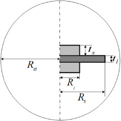
Model geometry 2D schematic view.
In both models, the equations implemented are the same, but in the 3D model, a vegetal tissue has been used instead of an animal one, and therefore it does not have blood perfusion.
The model of electric currents that has been implemented consists of three fundamental equations:
Equation (1) is the equation of continuity, derived from Maxwell’s equations, being
Equation (2) relates the current density to the electric field vector
Equation (3) relates the electric field to the applied voltage V.
From (2) we can obtain Eq. (4), where the parameters ϵ
r
and ϵ0 are the relative permittivity and the vacuum permittivity, respectively.
Table 1 shows the different electrical parameters used to model de problem. The electrical conductivities of air and steel, as well as their relative permittivities have been extracted from previous research [16]. The values of electrical conductivity and permittivity of the liver are selected according the literature, and these have been adjusted to fit to the average and peak current of the measured pulses.
Model electrical properties
The thermal model considers the heat generated due to the applied electric field and this model considers the heat loss due to the blood perfusion. The metabolic heat Q
met
is considered null. Equation (5) models the relationship between the heat flow
Equation (6) represents the relationship between the heat Q and the density 𝜌 of the material, its specific heat C
p
, the temperature T, and the blood velocity
Equation (7) represents the heat dissipated by the blood perfusion. The parameter ω
b
corresponds to the ratio of blood perfusion, T
b
is the blood temperature, 𝜌
b
is the blood density and C
pb
is the heat capacity of the blood.
Table 2 shows the parameters used for the development of the thermal model. The densities, thermal conductivities and the capacities have been extracted from the paper [17]. The temperature used for modelling the blood is the one initially measured in the organ before starting the electroporation treatment. The specific heat ratio has been extracted also from the literature and, finally, the blood perfusion rate has been used to adjust the model, starting from the initial value [8] found in the Table 2.
Model geometrical properties
Electric field measuring method
Model
In this study, cylindrical needles were selected, since they are easy to place and minimize sharp edge effects. Figure 3 shows some electric field distortions produced when they are placed in the tissue. This distortion must be minimized, since it disturbs the measurement and the effect of the treatment on the tissue.
In Fig. 2 the electric potential is represented along the centre of the tissue, to analyse the distortion produced by the electrode diameter. As it can be seen, the smaller needle diameter the less distortion obtained.

Representation of the longitudinal voltage distribution in the centre of the model with different needle diameters.
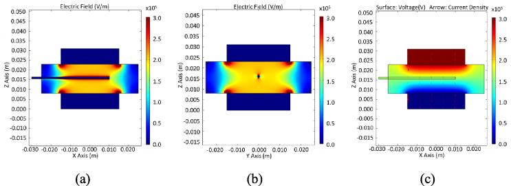
FEA analysis of the effect of the measuring electrode in the electric field distribution: (a) Distribution of the electric field in longitudinal section, (b) distribution of the electric field in frontal section, and (c) distribution of the electric potential, and lines of current in longitudinal section.
Another aspect that needs to be studied is the need of electrode insulation. To study this, the effect of the insertion of three electrodes with and without electrical isolation has been simulated. As shown in Fig. 4, it is necessary to isolate the electrode to minimize the impact in the measurement. If the electrode is not isolated, as in the Fig. 4(a), the voltage that we see at the end of the electrode is not the same as the voltage at the point we are trying to measure.
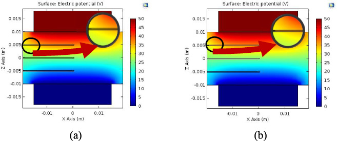
FEA analysis of the electrical isolation of electrodes: (a) needles without isolation, and (b) needles with isolation.
To evaluate both the electrodes and the designed models, experiments were carried out using potatoes as a biological tissue. Needles featuring 0.3-mm diameter were used in order to minimize electric field disruption. Moreover, they have been isolated using epoxy coating to achieve adequate measurements and minimum distortion.
As show in Fig. 5(b), three equidistant needle electrodes have been inserted in a potato slice. The electrodes are connected to differential voltage probes that record the measurements in a digital oscilloscope. To apply electroporation, two cylindrical parallel-plate electrodes are used, in order to achieve a sufficient contact surface to be able to have an almost ideal electric field in the centre of the tissue. The parallel-plate electrodes are connected to an IGBT-based H-bridge power converter.
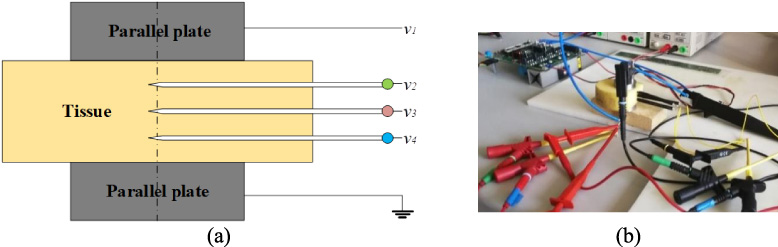
Experimental setup: (a) scheme and (b) setup photography.
In Fig. 6, it can be seen that with needle electrodes of 0.3 mm of diameter, it is possible to measure the voltage in different points with reduced impact in the treatment, as it has been studied in the model. With this method and the developed electrodes, it is possible to take measurements of the electric field applied during the application of the treatment, thus being possible to correlate adequately the results of the models, in addition to being able to carry out controls through the feedback of the electric field measured in different points.
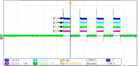
Measured voltages v i in the needles.
The proposed 2D model was created to reproduce an operating room setting. The experiment was carried out in vivo on pig liver. This experiment was approved by the ethic commission and was carried out with medical personnel qualified in facilities enabled for this type of experimentation.
The experiment was performed using a versatile high-voltage generator [9,11] with cylindrical steel electrodes, 3 cm in diameter and 0.8 cm in thickness. The applied treatment is based on 100 unipolar 3000 V pulses, 2 s separated. Measurements were taken of the applied voltage and current by means of an oscilloscope. The temperature was measured with a thermocouple in the centre of the liver.
Tables 1 to 3 summarize the geometrical, electrical and thermal properties used in the simulation, which have been obtained from values reported in previous studies [8,16,17]. The software used to simulate and represent has been Matlab and COMSOL Multiphysics.
Model thermal properties
Model thermal properties
Table 3 shows the geometric parameters of the model. The thickness of the liver corresponds to the average thickness of the real liver measured during the operating room experience. The thickness and radius of the electrodes corresponds to the actual measurements of those that were used. Finally, the radius of the liver and the air were selected to avoid edge effects.
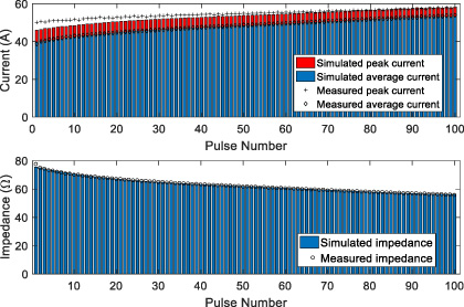
Comparison of experimental and simulated electrical signals.

Measured voltage and current waveforms.
Figure 7 shows the evolution of both experimental and simulated values of current and impedance extracted from the electrical signals represented in Fig. 8. Figure 9 show experimental and simulated temperature values. The temperature at the midpoint of the tissue can be seen with respect to time. This simulation shows the thermal dynamics of each applied pulse. It can be seen that the simulation fits to the temperature record carried out after the instantaneous application of each pulse. At this point, it is important to note that, due to the generator characteristics and the type of electrodes used, temperature control is essential.
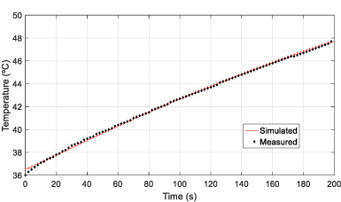
Comparison of experimental and simulated thermal evolution.
In Fig. 9 it can be seen that the applied power is high enough to raise the temperature up to 48 °C, yielding to some potential problems regarding the denaturation temperature of proteins. It can also be seen that the rise is practically linear, so if the treatment is extended it definitively may cause thermal damage to the liver tissue, reducing or eliminating the regeneration of it after the treatment.
Irreversible electroporation is a promising cancer treatment therapy, with significant advantages when compared with other alternatives. Modern techniques, in fact, are oriented towards the ablation of larger tissue volumes in a single treatment.
This paper has proposed a FEA-based model that includes both the electrical and thermal effects of the electroporation process. Thus, it can be used to simulate electrical parameters important for the power converter operation, as well as the thermal effects to avoid thermal damage to the tissue. An electromagnetic FEA 3D model that describes the application of electric pulses to a potato slice has been developed. The temporal evolution of the electric potential at different points, and its global distribution, has been studied. Different types of electrodes have been evaluated and the isolation requirements in them have been studied. In the tissue the needles are modelled and the discontinuities problems deriving from their positioning are studied. The proposed models have been compared with experimental results obtained during an in-vivo irreversible electroporation.
Footnotes
Acknowledgements
This work was partly supported by the Spanish MINECO under Project TEC2016-78358-R, by the Spanish MICINN and AEI under project RTC-2017-5965-6, co-funded by EU through FEDER program, by the DGA-FSE, and DGA under project LMP106_18, and by the MECD under grant FPU16/03765.