
Abstract
This paper examines the influence of pole and slot combinations on the electromagnetic performance of the flux-switching permanent magnet (FSPMs) machine. For this purpose, first the production of air gap flux density in machine analytically discussed. Next, five different pole and slot combination are selected by using the knowledge of air-gap flux density expression. The performances of the different combinations are analyzed and compared using the finite element analysis (FEA), and optimal pole and slot combination is suggested. It is found that the pole and slot combination has a dominant effect on machine performance and needs to be considered during the design stage.
Keywords
Introduction
In recent decades, flux-switching permanent magnet (FSPM) motor has gained significant attention due to vigorous rotor structure, high torque density, and good heat dissipation capabilities. FSPM motor has a similar structure as a conventional machine but uses a different working principle. Since all the excitation sources are placed on the stator, which provides excellent mechanical stability. FSPM motor applies the modulation flux and is a right candidate for direct-drive wind turbines where low speed and high-torque is required.
The history of FSPM machine back over 50 years [1], and more recently, this topic is selected by many researchers worldwide. The FSPMs machines accomplished many goals [2]. The analytical expressions of the FSPMs machine are derived using lumped magnetic reluctance networks [3], and the nature of back electromotive force (EMF) production and geometrical parameters that influence the machine performance are discussed in [4]. The performance of flux switching machine along with field winding and permanent magnet are compared in [5]. In reference [6], the torque production phenomena based on spatial harmonic was addressed. The irreversible demagnetization characteristics of magnets in FSPMs machines is described [7], and provide a guideline for improvement techniques.
However, all these prior investigations were restricted to the FSPM machines with 12 stator slots and 10 rotor pole numbers although other combinations can be possible for this machine. In this paper, first, the nature of the air-gap flux density production of an FSPM machine is examined. Next, using the air gap flux density information, the five different slot-pole combinations, 24-slots/20-poles, 12-slots/10-poles, 12-slots/8-poles, 6-slots/5-poles, 6-slots/4-poles are designed to analyze the back-EMF characteristics in detail with emphasis on the dominant influence of pole-slot combinations. The comparative study establishes that the choice of slot and pole has a meaningful effect on the performance and the better performance can be attained by selecting the proper slot and pole combination. The comparison draws the conclusion that the 6-slot/5-pole FSPM machine has a higher back-EMF. The experimental validation with different prototypes is difficult at this stage; therefore, the performance comparison is made by using a two-dimensional finite element analysis (FEA).
Air gap flux density of an FSPM machine
In the topology of FSPMs machine, the stator core is divided, and magnets are sandwiched between the core. The armature windings are installed in stator slots by overlapping the permanent magnets. Since all the excitation sources are housed in the stator side and rotor is mechanically stable. The structure of FSPMs machine is shown in Fig. 1. The negative and positive flux linkage is obtained when the rotor pole is aligned with the stator pole, called flux-switching action.
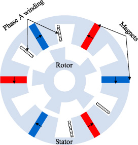
Topology of flux-switching PMs machin.
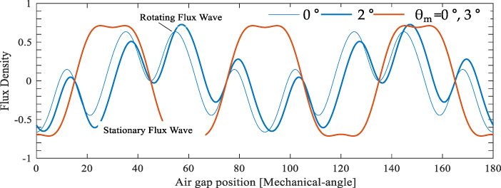
The waveforms when θ m = 0° and 3° showing the movements.
Magnitude and speed of working harmonics of Air gap flux density
The air gap magnetic flux density due to magnets can be computed as the product of airgap permeance function and Magnet Magnetomotive force (MMF). If the magnetic potential of the stator core pieces is considered constant, the MMF expression can be given as
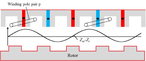
Conception of winding and fastest flux wave.
As aforementioned, the expression (5) shows that the air gap flux density of an FSPMs machine comprises of two flux waves; stationary and rotating flux wave, while only rotating flux wave Bmov.(θ, θ m ) will produce the back-Emf. Therefore, for an FSPM machine, one must focus on the Bmov.(θ, θ m ) term, the magnitude and speed of each working harmonic component of the air gap flux density are given in Table 1.
Pole and Slot Combinations Z
m
− Z
r
= −p
Pole and Slot Combinations Z m − Z r = −p
Specifications of the FE analysis
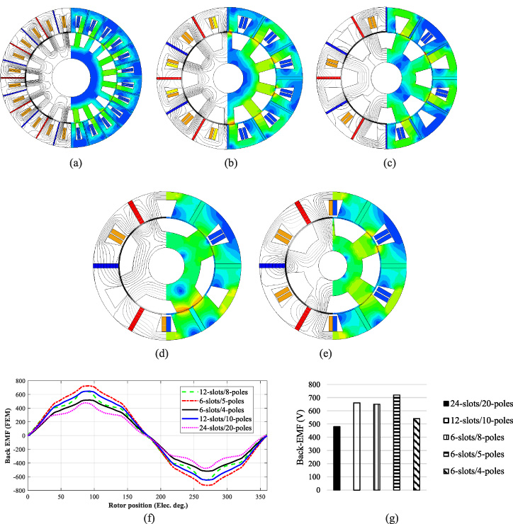
Structures of Flux switching PM machines and Phase back-EMF. (a) 24-slots/20-poles. (b) 12-slots/10-poles. (c) 12-slots/8-poles. (d) 6-slots/5-poles. (e) 6-slots/4-poles. (f) Phase back-Emf waveforms (g) Phase Back-Emf Spectra.
From Table 1, it can be seen that |Z m − Z r | pole pair has the most significant magnitude and fastest speed among these coefficients, which means this main flux component will offer the maximum contribution to the generation of backEMF. Consequently, to achieve better performance it is essential to place a winding considering this flux component.
For the slot concentrated three phase winding, the three slots constitute one winding pole pair p as shown in Fig. 3. In order to get the maximum flux linkage from main |Z
m
− Z
r
| flux component, it is necessary to apply the same number of winding pole pair, so the relation in (8) can be attained.
The choice of the slot and pole is made up considering expression (8) and the practical possibility for an FSPMs machine. The selection of magnet pole pairs Z m is directly related to the number of stator slots (Z s = 2Z m ) and winding pole pairs. For instance, for the machine IV and V, the number of Z m is 3, it should be noted that Z m cannot be selected 4 or 5 because it will make an even number of stator slots and three phase slot concentrated winding is not possible in this fashion. Moreover, when Z m is 3, the possible winding pole pairs p is 1 or 2 in 6 slots, thus; to fulfill the expression (8) condition only the 4 or 5 number of rotor pole can be possible as given in Table 2.
To investigate the influence of different slot and pole combination, the five combinations 24-slots/20-poles, 12 slots/10-poles, 12-slots/8-poles, 6-slots/5-poles, 6-slots/4-poles are designed. In order to check the effect of pole and slot combination on machine performance it is necessary to make a comparison on fair conditions.
Therefore, the total magnet area, turn per phase and dimensions including the air gap, stator outer diameter and stack length are designed with the same specifications in all structures. The detailed specifications are given in Table 3. In addition, the ratio of rotor slot opening to slot pitch has important effect on the machine performance and maximum back-EMF can be achieved when this ratio is 0.6 [5]. Therefore; the ratio of rotor slot opening to slot pitch is kept the 0.6 in all structures, in order to examine the effect of slot pole combination. Moreover, the double-layer slot concentrated winding has been employed.
At no-load condition, the phase back-EMF and spectra of all five structures are calculated at 1200 rpm by finite element analysis (FEA) and shown in Fig. 4. From the results, it can be seen that the 6-slot/5-pole FSPM machine has better performance than the commonly used 12-slot/10-pole structure. The investigation shows that higher slot-pole combination decreases the magnet thickness which in results MMF drop in the air gap. Besides, the higher slot-pole reduces the stator teeth width that increases the flux concentration in teeth and cause saturation that weaken the back-EMF. Therefore, the combination having small number of slots and poles is better for the FSPMs machine. The cogging torque is caused by interaction between magnets and poles so a large number of slot and pole combination will produce more cogging torque.
Conclusions
In this paper, the investigation of conventional FSPMs with different slot and pole combination is carried out, and the better combination is proposed. To accomplish this, first, a simplified analytical model is developed. From the expression of flux density, it is found that FSPMs machine has two flux waves in the air gap, while only one flux wave is rotating with rotor position and contribute to the back-EMF. The rotating flux wave comprises several flux components, however, the main contribution due to |Z m − Z r | pole pair and winding should be assigned considering this flux component. The previous studies used 12 slots and 10 poles to achieve this main flux component, but there are five more combinations has been applied to get this flux wave and back-EMF. It is found that the 6-slot/5-pole combination has the best electromagnetic performance for FSPMs machine. The selection of slot and pole combination is a very significant factor during the design stage of an electrical machine and this paper provides the approach to select the optimal slot and pole combination for FSPMs machine.
Footnotes
Acknowledgements
This work was supported in part by the Korea Electric Power Corporation (R18XA04) and in part by the Basic Science Research Program through the National Research Foundation of Korea funded by the Ministry of Education under Grant NRF-2016R1A6A1A03013567.
Conflict of interest
The authors declare no conflict of interest.