
Abstract
In order to develop long-lifetime neural electrodes, the insertion tissue injury caused by two optimized neural electrode (convex streamline electrode and vibration attenuation electrode) models were evaluated compared with a reference electrode. Based on the experimental evaluation system for testing tissue injury, the effects of insertion speeds on tissue injury of the two optimized electrodes with different insertion depths were studied. The maximum tissue strain caused by the two optimized neural electrodes firstly increased and then decreased with the increase of insertion speed at the depths of 3 mm and 4.5 mm. The insertion forces caused by vibration attenuation electrode are steady with the change of insertion speed. The convex streamline neural electrode caused less tissue injury compared with the other two electrodes. The higher or lower insertion speed causes smaller tissue strain for the two optimized electrodes, which is conductive to set implantation parameters to minimize tissue injury.
Introduction
Implantable neural probe, is the key component of brain-computer interface system [1]. It has been proved to be effective in the treatment of stroke, Parkinson’s disease, spinal cord injury and other diseases [2]. However, the application of neural probe is faced with the technical problem of poor long-term stability and short service life. One of the major reasons that lead to this problem is the tissue responses after implantation [3,4]. In vivo experiments show that the sustained tissue response will progressively lead to device failure over the long term [4,5]. According to previous studies, the acute tissue injury during implantation and the long-term micromotion-induced injury of brain tissue are the main factors to cause immune response, which result in an encapsulating scar at the probe-tissue interface [6,7]. Therefore, reducing the implantation injury and micromotion-induced injury of brain tissue is one of the main means to increase the service life of probes, which has become a hot topic in current neural probe research.
There are two main methods currently. One is to optimize the electrochemical properties of the probe [8]. Another is to increase the number of electrode sites by changing the shape and structure of the probe, thus enhancing the charge transmission capacity [9]. If the electrode sites are too close, it will result in a repeated recording of individual neuron informatio; On the other hand, if the distribution of electrode sites are too sparse, it would be difficult to discern the correlation of the action signal between neurons. Therefore, increasing the number of electrode sites properly and arranging their distribution rationally are of great significance for obtaining high quality recording signals.
Many studies have been conducted on optimizing the probe structure to effectively inhibit tissue injury caused by micro-motion and implantation [10,11]. Wu et al. [12] fabricated a fishbone-shaped polyimide probe. The tip of the probe is fishbone-shaped, and eight electrode sites are located on the top of eight side shanks, which are 100 μm apart from the main handle. In addition, the probe is coated with biodegradable silk protein coating in order to enhance mechanical strength during implantation, which has been proved to be manufacturable and implantable.
The fishbone structure could increase the number of electrode sites. However, the effects of fishbone structure on brain tissue injury in micromotion and implantation process is unclear [13]. Therefore, the impact of the multi-shank structure on the brain tissue injury needs detailed research, based on which to develop a long-lifetime neural probe.
In this study, an optimized multi-shank probe was proposed based on the fishbone structure, considering the signal intensity and the optimal distribution of electrode sites. The micromotion-induced injury and insertion injury of brain tissue caused by the optimized probe were analyzed by numerical simulation and experimental evaluation method respectively. The finite element analysis was conducted and the experimental evaluation system for testing tissue injury [14] was set up to evaluate the effects of the multi-shank probe. The optimized design and evaluation method in this paper is supposed to be significant for the optimal design of neural probe and is conductive to improve the stability of neural probes in a long term.
Materials and methods
The numerical simulation evaluation
Based on this fundamental design of Wu et al. [12], the structure and the distribution of electrode sites would be optimized in this study. According to the research of Eaton et al. [15], each electrode site can collect the electrical signals within 130 μm. However, other studies have shown that the maximum distance is much less, somewhere about 50 ∼ 100 μm [16,17]. In this paper, the measurement range of each electrode site is considered to be a circle with a radius of 100 μm, so the optimal distance between the two electrode sites is 200 μm. Then the probe can measure the signal in the range of measurements completely. Based on this theory, a new multi-shank probe is designed in this paper, as discussed below.
The tip of the optimized multi-shank probe (coded as O probe) is shown in Fig. 1(a). The main parameters: w = 85 μm, a = 200 μm, b = 200 μm, c = 16 μm, R1 = 50 μm, R2 = 20 μm, R3 = 80 μm. There are 12 sites on this probe, which are distributed on the side shanks and the main handle. The distance between the adjacent sites is the optimal distance of 200 μm. Compared with the fishbone-shaped probe proposed by Wu [12] (coded as F probe), O probe has been improved in structure. The number of electrode sites increased from 8 to 12, and the optimal distribution of the sites were obtained. In addition, fillets were adopted at the corners and the tips of the side shanks to reduce the stress concentration.
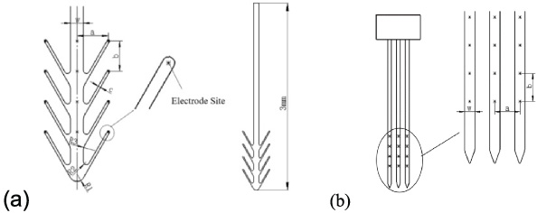
The model of the optimized multi-shank probe. (b) The geometry model of T probe.
Material properties of the brain tissue [21]
The O probe was compared with the widespread used single-shank probe A1x16-3mm-50-177 (Neuro-Nexus Technologies, Ann Arbor, MI) (coded as S probe), F probe, and the commercial three-shank probe with the same electrode site distribution (coded as T probe) respectively. And the micromotion-induced injury of brain tissue was assessed by the maximum tissue strain.
The geometry model of T probe was illustrated in Fig. 1(b). The main parameters w = 83 μm, a = 200 μm, b = 200 μm. It is obvious that the T probe has the same site distribution with the O probe proposed in this paper. The area of micro-motion injury in brain tissue usually ranges from hundreds of microns around the probe [18]. Thus, the centerline of the probe was selected to be 750 μm from the boundary of brain tissue in order to capture all the strain field due to tissue micro-motion and eliminate the influence of boundary effects. The 3D finite element models of the probe-brain tissue interface were developed in ANSYS Workbench 15.0 (ANSYS, Inc., Canonsburg, PA). The silicon-based probe was considered as a linear elastic model with a Young’s modulus of 200 GPa, a Poisson’s ratio of 0.278 and a density of 2.34 g/cm3 [19,20]. The biomechanical property of brain tissue was described by isotropic hyper elastic and viscoelastic constitutive mode [18], which can be established by the equation (1) and (2). Where, 𝜆 i is principal stretches, μ and 𝛼 are material constants, g k is the relaxation coefficients and τ k is the characteristic relaxation times. The parameters used in this paper are shown in Table 1.
Referring to the experimental data measured by Gilletti et al. [22], a 10 μm displacement with a frequency 4 Hz was applied to the upper surface of the probe for dynamic analysis. The number of shanks of the optimized probe were changed. The brain tissue damage caused by 6 different probes with different number of shanks (2, 4, 6, 8, 10, 12) were studied using the finite element simulation method.
In order to evaluate the insertion injury caused by the O probe and the T probe, the two probes were implanted into the brain tissue model on our experimental evaluation system. The structural probe model was fabricated by AEMD Lab (Shanghai Jiao Tong University). This study focused on the effects of shape and structure on the tissue injury. The internal circuit was not considered. Figure 2 shows the probes under microscope, including (a) O probe and (b) T probe.
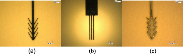
The model of silicon probes: (a) O probe, (b) T probe, (c) O probe with silk protein coating.

The evaluation system for testing tissue injury.
In this experiment, silicon rubber and optimal speckle pattern were used to simulate the brain tissue [14]. The speckle pattern was verified to be high-quality with the mean intensity gradient (MIG) parameter [23]. The motion of speckle pattern before and after deformation on the material surface can be recorded by the digital microscope (×50). The displacement and strain of tissue can be extracted by the digital-image correlation method [14,24]. In order to improve the mechanical coupling property between the probe-brain tissue interface, silk protein coating was adopted on the surface of the probe (Fig. 3(c)), which can degrade in vivo from 30 minutes to 25 hours [12]. In this study, a series of silk protein solution of different concentration were prepared, and the O probe samples were dip-coated with different silk protein solution to assess the effects of solution concentration on tissue injury. The silk protein solution was made with a percentage of silk protein powder and water, mixed with the mixer (DF-101S) at 35 °C. The probes were dipped in different silk protein solution only one time with the withdrawing speed of 50 mm/s from solution. The coated samples were laid at normal temperature for 24 hours.
The evaluation system for testing tissue injury [14] was set up as shown in Fig. 3. The system is composed of three modules: (a) load module for simulating neural probe implantation process, including X-axis step motor driven micro platform (ALS-602-H1M), Z-axis micro platform, NMB force sensor (UT-100GR, 980.7 mN) and stage controller (CHUO SEIKI, QTCM2); (b) data acquisition module, including digital microscope (KEYENCE VHX-500) to capture micrographs of speckle pattern on the tissue surface and data acquisition system (PCD-300a, KYOWA). (c) post processing module, including personal computer and Vic-2d software for extracting tissue deformation information from the captured speckle patterns. In order to change the implantation location, the brain tissue phantom can move along Y-axis.
The implantation site of the neural probe was cerebral cortex which was composed of gray matter, and the thickness of gray matter varied from 1 mm to 4 mm. So, 3 mm were set as the insertion depth to ensure that the multi-shank structure of the probes can be inserted into cerebral cortex completely. 0.05 mm/s, 0.1 mm/s, 0.5 mm/s, 1 mm/s, 1.5 mm/s, 2 mm/s were set as the speed parameter. The silk protein solution of different concentration (0.1 g/ml, 0.2 g/ml, 0.3 g/ml, 0.4 g/ml) were prepared. It has been verified that when the concentration was set as 0.5 g/ml, the solution has reached a saturation state. In the experiment, the magnification of the digital microscope was set as 50× and the region of interest (ROI) was 1500 × 1300 pixels. A subset size of 41 pixels and subset spacing of 2 pixels were chosen for the DIC calculation. In addition, the commercial software Vic-2D was used to calculate the strain field of the brain tissue phantom with the digital image correlation method [24], and the insertion force was collected by the force sensor NMB (UT-100GR, 980.7 mN).
The maximum tissue strain caused by O probe, S probe, F probe, and T probe were shown in Fig. 4(a). Compared with S probe, O probe greatly reduced the brain tissue strain by 96.98%. Figure 4(b) shows the tissue strain caused by probes of different number of side shanks, indicating that the probe with few side-shanks would cause large tissue injury. When the number of side shanks is more than 6, the strain of brain tissue decreases significantly (more than 80%) and tend to be stable. It can be inferred that when the number of probes reached 6 and above, the contact area between probe and brain tissue increased and the mechanical coupling property is enhanced, which reduced the injury of the brain tissue caused by micro-motion.
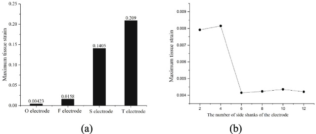
The maximum tissue strain caused by four probes and by (b) probes with different number of side shanks.
The numerical simulation results show that O probe designed in this paper performs well in enhancing signal intensity and reducing micromotion-induced injury. In order to further evaluate the effectiveness of O probe for improving lifetime, O probes coated with different concentration of coatings and T probe were investigated. They were implanted into brain tissue phantom at different speeds on the experimental.
Figure 5(a) shows the relationship between the tissue strain and insertion speed. The O probes with different concentration of silk protein coatings were evaluated with the reference of T probe. It can be seen that compared with T probe, O probes can effectively reduce the brain tissue strain. As to O probe, a smaller strain was obtained at a lower speed (<0.1 mm/s). The reason is probably that lower speed could lead to minimal vibration and mechanical shock and allows more relaxation and recovery after the deformation and rupture of brain tissue phantom [25]. However, the tissue strain of T probe decreased and tended to be stable when with the insertion speed of 1 mm/s and above. It is assumed that when the probe is implanted with a high speed, the brain tissue is quickly cut off rather than gradually deforming until being torn, which helps to reduce the tissue injury [26]. Therefore, it can be concluded that high speed implantation (>1 mm/s) can effectively reduce brain tissue injury for the bare probes without silk protein coatings.

The relationship between the tissue strain and insertion speed and (b) the concentration of silk protein coatings.
Figure 5(b) shows the curve of the brain tissue strain with the concentration of silk protein coatings at the insertion speed of 0.5 mm/s. It can be seen that with the increase of the concentration of silk protein coatings, the strain value of brain tissue is smaller. This is probably because the stiffness of the coating becomes closer to that of brain tissue when the concentration of silk protein changes from 0.1 g/ml to 0.4 g/ml, leading to a better mechanical coupling property between the coating and brain tissue, and effectively reduces the brain tissue injury.
In this work, an optimized multi-shank probe was proposed considering the mechanical property and the optimal distribution of electrode sites. The micromotion-induced injury and insertion injury of brain tissue caused by the optimized probe were evaluated by numerical simulation and experimental evaluation method respectively. In details:
(1) Compared with the S probe, F probe and T probe, the optimized probe greatly reduced the brain tissue strain by 96.98%, 72.73% and 97.98%. It can be speculated that the structure of the probe will significantly affect the mechanical state of the probe-brain interface, and the multi-shank probe can reduce the micromotion-induced injury effectively. (2) The multi-shank probe with few side-shanks would cause large tissue injury. When the number of side shanks is more than 6, the strain of brain tissue decreases significantly (more than 80%) and tends to be stable. (3) Compared with the T probe, the optimized probes can effectively reduce the brain tissue strain. And the optimized probe is suggested to be implanted at the speed of above 0.1 mm/s to get a better performance. (4) With the increase of the concentration of silk protein coatings, the strain value of brain tissue and the implantation force of the probe become smaller. It is further verified that the optimized multi-shank probe is conductive to reduce the brain tissue injury and the reduction becomes more obvious when the coating concentration gets bigger.
Footnotes
Acknowledgement
This work was supported by the National Natural Science Foundation of China (No. 51675330).
Conflict of interest
The authors state that there is no conflict of interest to report.