
Abstract
In order to analyze and design the Interior Permanent Magnet Synchronous Motor (IPMSM), the parameters must be defined according to characteristics of the motor. To obtain a good motor, the decrease of leakage flux is done by reduction of mechanical stresses and increase of the magnetic flux density. The magnetic flux distribution in the air gap is first analyzed. Then, the rotor is designed by using a specific mathematical model. Two topologies based on placing of permanent magnet into the rotor, which is placing in parallel shape and V-shape, are analyzed and designed. The mechanical stresses and rotor strains occurring during the rotation at high speed are studied.
Introduction
In the propulsion system of electric vehicles (EVs), an internal combustion engine (ICE) is replaced by an electric motor because of the environmental problems [1]. There are two main types of electric motors widely used in the EVs: induction motor (IM) and permanent magnet synchronous motor (PMSM) [2]. The Permanent Magnet (PM) machine is very attractive for energy systems due to its high efficiency, torque density and reliability [3].
Comparing to the use of surface PM motor, using Interior Permanent Magnet Synchronous Motors (IPMSMs) is more interesting in various industrial applications. Due to their specific advantages, such as low noise, robustness, small air gap, and large speed ranges operation [4–8]. However, there are some drawbacks due to their special topology.
IPM machine topology suffers from the complex geometry of the rotor and the high ratio of flux leakage [3,9,10]. There are parameters that limit the design, such as the size of the permanent magnets, their location and the flux barrier geometry which must be considered. Many geometrical and design solutions have been proposed in order to reduce the flux leakage. However, the drawback of these solutions is weakness for the mechanical properties of the rotor [11–15].
It is well known that rapidly rotating systems such as rotors are subjected to mechanical and electromagnetic solicitations which can be considerable in terms of reliability of their machine elements (centrifugal force and rotor - stator interaction, respectively). Because of their geometry (small section, slender shape, etc.) some parts of the rotor are likely to deform significantly and reduce the reliability of the motor. Since the most sensitive area for the mechanical stress arises on the bridge of the rotor (see Fig. 1 where the zoomed bridge is in the pink circle), the thickness of the bridge, denoted e, will be one of the main parameters, which relates to the electromagnetic and mechanical stresses.
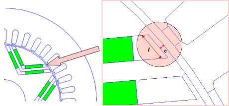
Sensitive area (bridge of length l and thickness e) where the mechanical and magnetic stresses must be analyzed.
To increase the efficiency of the electric motor, it is necessary to increase the magnetic flux passing through the rotor towards the stator and decrease the flux leakage in the bridge and ensure that the rotor does not undergo plastic strains when changing the bridge thickness.
Therefore, the general idea is that reducing flux leakage requires very thin bridges, while increasing mechanical robustness needs to increase the thickness of the bridge.
In this paper, two rotor structures have been studied in order to find the compromise between magnetic and mechanical requirements.
One of the two studied topologies is chosen for further study of mechanical stresses and strains which is finally manufactured to validate the theoretical results.
In this section, a study of magnetic flux density distribution of an interior permanent magnet motor is investigated. Two machine topologies (parallel shape and V-shape) are considered. The performances of two topologies are analyzed and compared for the same volume of the magnet. The result of this analysis leads to an optimal design of the motor.
Two dimensional (2D) finite element (FE) model is developed for analysis of PM machines behavior. The first step consists to analysis of the flux density distribution in the air-gap and its spectral content. Magnetic saturation needs to be correctly taken into account in order to analyze the magnetic behavior of the bridges when they are highly saturated.
Using a 2D approximation, the phase flux can be evaluated by introducing in magnetic vector potential (A) formation:
The amount of leakage flux due to the bridges is important quantity that should be checked. It is evaluated by the standard method
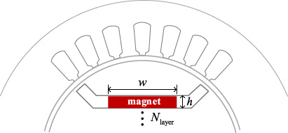
The optimization process consists in choosing the number of layers N
layer
, the height (h) and the width (w) of the magnets (Fig. 2) so that the phase flux (𝛹
phase
) is maximum:
The developed mathematical model of PM motor is used for analyzing parallel shape PM motors performances. The shape and the magnitude of the magnetic flux density depend on the dimension of the magnets and their locations.
Parameters of optimization process.
Figure 3 illustrates the optimal geometry as position of the magnet in parallel-shape as well as the air-gap flux density waveform and its spectral content. The permanent magnets are highlighted in green.
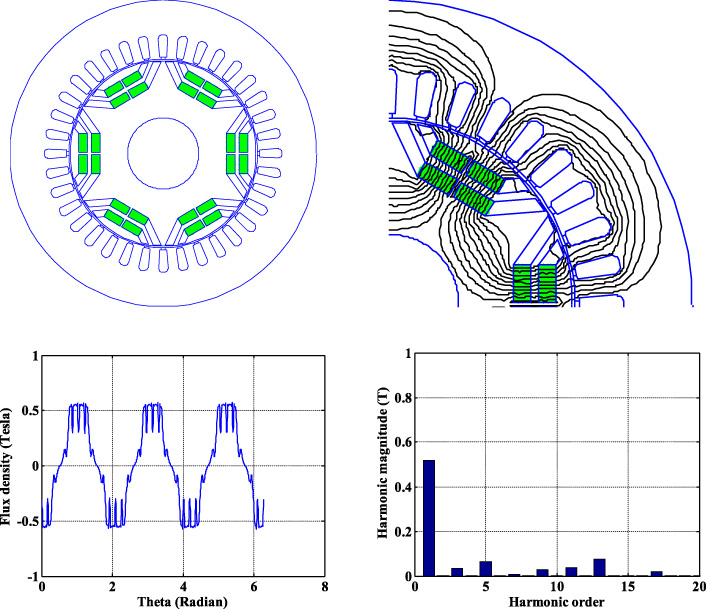
Rotor topology: Placing in parallel shape.
The V-shape topology of PM machine is well known for benefit of flux concentration. This topology is investigated to compete with parallel shape topology. The same design approach describe above is applied to optimize rotor topology. The results are depicted on Fig. 4.
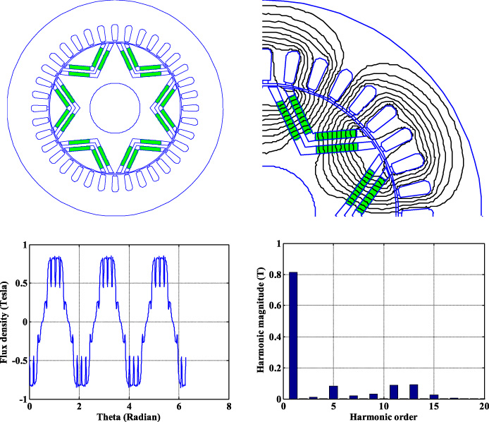
Rotor topology: Placing in V-shape.
As predicted, thanks to the flux concentration property the V-shape topology has better results than parallel shape topology. The flux density magnitude reaches 0.8 Tesla which is usually recommended in the design. The harmonic content is still acceptable.
At this step of design, it is interesting to highlight and quantify the effect of bridge thicknesses on the flux leakage.
For the optimal V-shape topology, the flux through the bridges is calculated for many the bridge thicknesses.
It is predictable that increasing the bridge thickness increases the flux leakage. But it is useful to evaluate its effect on the back-EMF and electromagnetic torque. Figure 5 shows the amount of flux leakage according to the bridge thickness for the V-shape topology motor.
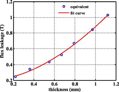
Effect of bridges thickness.
However, to design a good motor, not only magnetic analysis but also the mechanical stress analysis should be considered.
In this section, the mechanical analysis of the bridge is carried out in infinitesimal transformation. In a general case, both centrifugal and ferromagnetic forces are considered. The mechanical quantities considered in the model are as follows:
displacements u (X, t) strain tensor ϵ(X, t) stress tensor σ(X, t)
The mechanical constitutive law of the bridge material is assumed elastic linear and isotropic (Hooke)
Finite element simulations using ANSYS Workbench have been carried out to confirm the theoretical study. In a first step, the original value of the thickness of the bridge is about 0.775 mm. The length of the bridge is 2.93 mm. The von Mises equivalent stress and strain are given in Figs 6 and 7, respectively. The maximum value of the stress is found about 2.4 MPa.
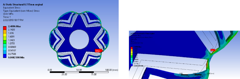
FEM simulation giving the distribution of the stresses in the rotor. The maximum von Mises equivalent stress is located near the middle of the bridge.
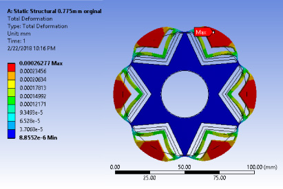
FEM simulation giving the distribution of the equivalent deformation in the rotor.
This results in a safety factor of 104 when compared to yield strength of silicon steel [16]. The DC attraction forces acting on the rotor surface are computed with the magnetic pressure
The parameters used for the simulation are detailed in Table 1.
Parameters of mechanical simulation using ANSYS
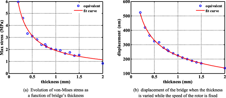
In a second step, the study is carried out with changing the bridges thickness. The results are given in Figs 8 and 9. In Fig. 8(a), the equivalent von Mises stress is illustrated when the bridges thickness varies. The blue dots are the results obtained from the simulation whereas the red line indicates the fitting curve. As it can be seen, the stress decreases when the thickness increases, which corresponds to the strain (deformation) depicted in Fig. 8(b). Moreover, the result of study on the stress when the rotor speed varies is given in Fig. 9. It is found that the higher the speed, the greater the stress and the strain obtained. Even at 15000 rpm, the strain is well below air-gap width (0.5 mm). These results are obtained considered at the center of the bridge.
Maximum von Mises stress and maximum displacement at the red zone of Fig. 7 (𝛺 = 15000 rpm).
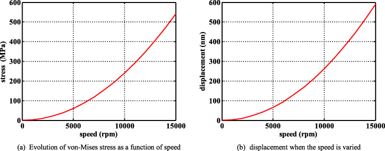
Equivalent von Mises stress and displacement of the bridge when the speed is varied. These results are obtained considered at the center of the bridge (e = 0.775 mm).
The magnetic and mechanical analysis presented above concludes that V-shape rotor is more suitable to improve the performances of the machine while mechanical stress and deformation are below the critical limits. The IPM motor is designed for air conditioning application with medium speed of the drivetrain 10000 rpm.
A 36 slots 6-pole machine topology is chosen for this purpose. According to the mechanical constraints, the air gap length is fixed to 0.5 mm. The mechanical information is enough below this value.
The full magnetic design of this machine is carried out with standard approach using 2D finite element model. The final mechanical behavior is analyzed using ANSYS Workbench. Additional design parameters of machine are given in Table 2.
Parameters of studied Interior PM motor
Parameters of studied Interior PM motor
The designed machine is prototyped with standard stator. The rotor lamination is shown on Fig. 10 as well as the final assembly including shaft and inset PMs.
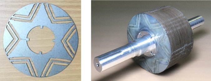
Prototype of the proposed rotor.
The experimental results of the back-EMF waveforms and its spectral analysis which correspond to the specifications of the motor are given in Section 5.
To validate the proposed rotor structure considering the mechanical stress and magnetic flux density distribution, the test bench is developed and shown in Fig. 11. The studied motor is coupled with a motor acting as a prime mover. The oscilloscope was used to capture the back-EMF voltages.
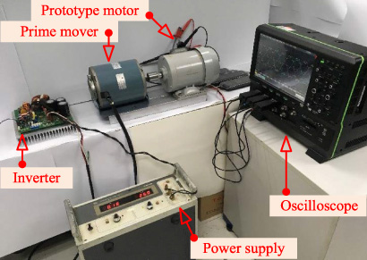
Test bench for back-EMF measurement.
The back-EMF voltage waveforms are indicated in Fig. 12. Several tests were conducted for different speeds. The simulation result (Fig. 12(a)) is obtained using the finite element software FEMM linked with MATLAB. The peak value of the back-EMF is about 240 V. The waveform is nearly sinusoidal due to existing of the fifth-harmonics of the flux density the back-EMF. The experimental result is shown in Fig. 12(b) for the speed of 1,000 rpm.
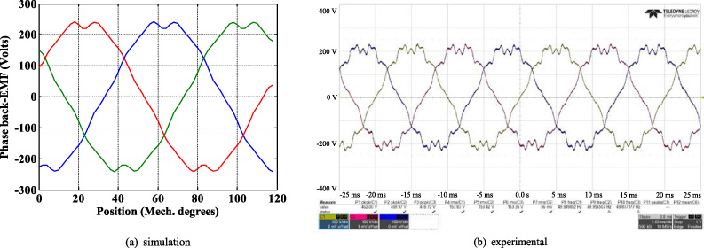
The back-EMF phase voltage at 1000 rpm.
For the simulated back-EMF voltage (line-line) shown in Fig. 13(a), the peak value is about 422 V. The experimental result is given in Fig. 13(b) to compare with that obtained by the simulation. The experimental result has a good agreement with that obtained by the simulation.

The back-EMF voltage (line-line) at 1000 rpm.
Interior Permanent Magnet Synchronous Motor (IPMSM) is analyzed and designed for reduction of leakage magnetic flux density. To do that, mechanical stress and magnetic flux distribution in the rotor are considered. Two structures of inserting permanent magnets were studied. From the result, the V-shape offers higher air-gap flux density. Therefore, it is further implemented and tested. The experimental results show a good agreement with the results obtained with FEMM finite element software.
Footnotes
Acknowledgements
This work is supported in part by the Office of the Higher Education Commission (CHE), the Thailand Research Fund (TRF) under research grant for new scholars-MRG5980261, the Rajamangala University of Technology Suvarnabhumi, the faculty of engineering and architecture (FEA-RUS), Thailand, Embassy of France in Bangkok, Thailand, and in part by the Groupe de Recherche en Electrotechnique et Electronique de Nancy, LEM3, University of Lorraine, Nancy, France.