
Abstract
Crack orientation is a vital factor in the behavioral study of fractures, especially the study of crack propagation in structures that are under dynamic or fatigue loading. Indeed, many non-destructive testing (NDT) techniques have been developed recently for the detection of cracks such as the eddy current testing (ECT). However, the crack orientation has not been undertaken into consideration. In this paper, a NDT based on eddy current using 3D finite element modeling, is proposed for the determination of the crack orientation. The idea of this proposed technique benefits from the influences of crack orientation, which can be observed on the components of eddy current and the related magnetic flux density following the x, y axes, for the estimation of the crack angle orientation based on an interpolation criteria. The obtained results through the presented simulation prove the validity of the proposed technique for the detection of crack angle orientation.
Keywords
Introduction
For many decades, the long term durability of structures and materials, and their resistance against deterioration mechanism such as cracks and corrosion under the external environmental effects and the exposure to overloading, were a major challenge for the researcher and industrial partners. Where, the main aim was to design and produce new materials and to develop highly valuable new tools to ensure the diagnosis of existing structure and material to improve their durability, decreasing their troubleshooting time, and saving money. On the other hand, the most important aim is to save lives, especially those who are involved in works, that require high prevention such as civil engineering building, mechanical engineering, aeronautical engineering, petroleum engineering, marine engineering and shipbuilding, electrical engineering, … etc. Ergo, many researchers, engineers, and industrial partners are developing several new strong materials that can support the aforementioned constraints and improve the lifespan of their structure.
One of the actual major problems which cause the deterioration of the materials used in different structures is the cracking phenomenon, especially microscopic cracks, which shorten the lifespan of materials in many vital structures and infra-structures quite significantly, and are presenting a serious danger for mankind and the economics such as civil and industrial building, civil engineering structure, ships, airplanes, plants, and transportation means in oil and gas, electric power plants … etc, where the occurrance of sudden crack growth presents a serious risk on the stability and reliability of structures and operating personel. In this context, this important critical phenomenon has attracted the attention of potential researchers, to develop techniques and tools, which allow the prediction and the diagnosis of the non-observable hidden microcracks and their geometric parameters (length, width, depth, orientation, …). Furthermore, many other researches are focussing mainly on the study of the behavior and mechanism of cracks propagation which still up to date need more research efforts.
It is obvious that to understand the physical behavior of the cracks, it is primordial to identify their causes and origins. Indeed, the main origins causing such physical phenomenon are the fabrication faults and anomalies, highly overloading, thermal, chemical and, environmental effects (freezing-thawing, humidity, corrosion … etc). All these associated effects were theoritically presented in several previous works [1–10], although these studies are limited as the techniques and tools of the identification, diagnosis, prediction and localization of the cracks and their geometrical parameters are still limited.
With the actual development of measurements, data analysis, and sensors, it becomes possible for researchers to develop new approaches and techniques of identification, detection, localization, and even prediction of different kinds of cracks and their orientation from macro-scale to micro-scale. In fact, the approaches that were used in micro-scale were belonging to the non-destructive testing (NDT) techniques family, which were used in industry as testing and analyzing techniques for the assessment of the main properties of materials, components, structures and systems under use or under operation without causing any kind of damage to the objects being tested. These techniques can be found in the literature also under the names of non-destructive evaluation (NDE) and non-destructive examination (NDE). The most frequently used techniques in NDT are magnetic-particle, liquid penetrant, radiographic, ultrasonic, visual testing, and eddy current testing.
In the recent years, many NDE methods based on the electromagnetic field analyses have been presented in several previous publications and which have been used mainly for crack and flaws detection in materials such as the eddy current testing (ECT), the magnetic flux leakage testing, the magnetic particle inspection, the remote field testing, and the alternating current field measurement. Wherein, it is well known that the eddy current testing (ECT) is the most known electromagnetic field based NDE technique that is used widely in detection of flaws in different vital structures. In fact, the birth of the eddy current (EC) in objects of conducting materials under test is due to the presence of electromagnetic induction when the these objects are placed in front of probe coils, which produce a time-variable magnetic field when they are fed by a specific alternative current [11–21]. This resulted reaction from the application of the electromagnetic field in the materials or objects under test allows obtaining their detailed characteristics, which have to be assessed and analyzed for the detection of eventual occurred anomalies. However, we can arguably say that actually academics, industrialists and practitioners are all still investigating and developing new eddy current probes topologies with higher sensibility and precise detection to reach the ability of the prediction and sizing of the flaw degree in structures and objects under test.
In the present study, the detection approach based on the eddy current testing has been chosen to be the main tool of detection due to its great effectiveness in detecting cracking defects with high accuracy. This technique has been widely used in several applications and structures as tools of crack detection. It has been also used for corrosion detection, detection of fatigue dangerous zones in structures, thickness detection of layers in composite materials, and even for the detection of microscopic cracks.
The present study will mainly focus on two points, the first is the study of the influence of the crack orientation on the eddy current created in the material or structure under study, the second is performing an investigation on the relation of interaction between this kind of currents and the state and orientation of cracks.
Indeed, during the last three decades, only a few researchers were interested in the use of the eddy current for the detection of cracks and their orientations. In 1995 Yu Pei Ma et al. developed a new technique for inducing the extended eddy currents in metallic structures which was tested on a conducting plate allowing them to detect subsurface flaws using a superconducting quantum interference device (SQUID) magnetometer, this detection was not possible to be obtained by a conventional eddy current surface probe [1,2].
In 2004 L. Perz et al. designed and built a magnetic imaging system associated with eddy current technique for quantitative analysis of the fatigue cracks under rivet of aircraft aluminum alloys in planar structures. Where to achieve more accurate measurements of the magnetic field induced by the eddy current distribution in the tested materials, improved solid-state magnetic sensors based on giant magnetoresistance (GMR) were used [3,4].
In 2006 Dolabdjian et al. proposed a detection approach of fatigue cracks close to fasteners or rivets using an improved rotating head built around an improved giant magneto-resistance magnetometer (IGMRM) and a well designed electromagnetic flux focuser, where it was found that the proposed technique seems to be very accurate and reliable for subsurface crack damage detection [5].
In 2009, Rimond et al. implemented a 3-D finite-element model using an IGMRM where a simple single wire was used as an inducer which was applied for the detection of corrosion on reference samples [6]. This same proposed technique was used one year later by the same authors to evaluate the detection performance of a benchmark NDE eddy-current system, where their proposal model was based on a modified magnetic vector potential and a reduced magnetic scalar potential within conducting and nonconducting regions, respectively. In fact, the authors proved through their obtained results the existence of an optimal frequency which can be used for subsurface crack detection, especially for thickness and conductivity of the simple plate under tests [7].
In 2010 Lei Yin Zhao et al. and Zhang et al. conducted a research benefitting from their research presented in 2007 [8], in which they demonstrated that as the coil flare angle decreases, the eddy current density distribution in the conductor is more concentrated, the temporal waveform is steeper and the resulting spikes of induced electromotive force (EMF) in the coil has an increased value. At the same time, they pointed out that the conductivity and permeability of the plate conductor under test expend more effect on the eddy current density and the waveforms of the coil EMF than the plate thickness. The authors used the results carried out from their research for predicting pulsed signals of eddy current and in the design of new probe topologies [9].
In 2012, G. Yang et al. developed an eddy current-giant magnetoresistive (EC-GMR) sensor system where the authors did prove its ability for the detection of the subsurface cracks at fastener sites based on aluminum fasteners [10].
In 2014, H. Rimond et al. proposed a technique which was carried out numerically and experimentally, where the authors used a new excitation technique to improve the detection of deep cracks of any orientation, this technique was based on generating a pseudo-rotating AC magnetic field which gave birth to a pseudo-rotating eddy current in the tested materials where the resulting signal was measured by an IGMRM [1]. In the same year, Guang Yang et al. proposed the idea of a rotating electromagnetic field which is designed to ensure the rotation of the applied magnetic fields and the corresponding eddy currents based on electrical principal without using mechanical tools, where the main goal was to allow the sensor to possess the property of uniform sensitivity in detecting cracks in all radial directions around fastener sites under study [22].
In 2015, Chaofeng Ye et al. proposed a prototype probe which was validated theoretically using a finite-element model and tested experimentally in diagnosing a two-layer aluminum sample. It was based on a new approach using two giant magnetoresistive sensor arrays in a differential configuration to reduce the impact of the background field and increase the signal-to-noise ratio [23].
In 2016, Mengban Fan et al. studied the possibility of finding the optimum excitation frequency to enhance surface defect performance in terms of detection sensitivity, contrast between defect features, and classification accuracy based on two main approaches such as the kernel principal component analysis (KPCA) and the support vector machine (SVM). The main contribution presented by the authors is that the influences of excitation frequency on defect characterization performance are interpreted, and the optimal excitation frequency for a group of defects following the optimal characterization performances was carried out experimentally [24].
In 2019, Chaofeng Ye et al. presented an eddy current (EC) probe based on orthogonal excitation coils that has the ability to change the exciting current direction electrically without a mechanical tool where a tunnel magnetoresistive (TMR) sensor was used for the examination of samples of stacked carbon fiber reinforced polymers (CFRP) [25]. In the same year Repelianto et al. proposed a new design of a rotating uniform eddy current (UEC) probe named as the rotating butterfly probe. It was built based on two pairs of excitation coils topology placed perpendicular to each other but in two different layers. It was proved that this topology can provide larger induction and enhance the sensitivity of flaws detection. Furthermore, this proposed probe was tested experimentally on a sample of aluminum plate where it was carried out that the detection of flaws can be achieved in all directions [26].
Indeed, during the last years, many researches were interested to ensure the detection of an embedded crack with any orientation using rotating focused eddy current without the aid of mechanical tools, which may cause the generation of noises affecting the accurate measurments and sensing. Very recently, X. Zhiyunan et al. has developed a rotating focused eddy current which has been created by two pairs of coils on the shape of eight placed orthogonally to each other in the same layer. It has been proved that it presents good sensitivity for detecting the crack within all directions. However, the authors of the present paper have highlighted a major drawback in this topolgoy which is the identical magnetic flux density curves for all crack orientations in terms of value and form. It means that the authors have not taken into account the crack orientation effect which has an significant impact on the main parameter calculation in fracture mechanics as it will be explained in more detail in Section 2 of this paper [27].
The following sections of this paper are presented as follows: In Section 2, the definitions of the most important principles of fracture mechanics are presented, then the importance of crack orientation and how to use it for the calculation of important parameters of fracture mechanics are explained. In Section 3, a detailed description of the 3D finite element model of the proposed model of the eddy current induced by a multi-turn coil in a plate with an oriented crack. In Section 4, the influence of crack orientation on the components of eddy current J x et J y and the magnetic flux density B x et B y , is analyzed. Finally, empiric relations for the estimation of the orientation angle based on the eddy current and magnetic flux density components are carried out. This paper ends with a conclusion.
Fracture mechanics and crack orientation
Fracture mechanics was introduced for the first time in the early of 20th century by the founding papers published by Inglis (1913) and Griffith (1921), which introduced the first development of the elastic fracture mechanics as a branch of mechanical engineering and offered a great contribution toward understanding the propagation of initial flaws in structures and materials. Since then, it is considered as a scientific discipline that deals with the study of the mechanical behavior of crack phenomena and its propagation in natural and man-made structures and materials [28–30]. Indeed, this discipline is divided into two main fields, the first field is the linear elastic fracture mechanics (LEFM), it is applicable when the dissipative processes remain limited within a small region around the crack tip based on the criterion of brittle fracture in comparison to the structural dimensions which can lead to sudden disastrous failures in structures or materials [28], it was originally established by Griffith between 1921 and 1924, where he defined for the first time the basic theory of fracture and presented the direct relation between the defect size and the fracture stress [30]. Between 1957 and 1958 Irwin modified the Griffith’s elastic surface energy expression by adding a plastic deformation energy or plastic strain work in the fracture process, where he introduced the stress intensity factor K (Pa⋅m0.5) as a control parameter of the critical state of a crack [31].
The second field is the non-linear fracture mechanics (NLFM), it concerns the study of ductile fractures, which involves the cracks in solid bodies possessing nonlinear consecutive response. This nonlinearity can be explained by a finite deformation geometry, a nonlinear elastic behavior of the material or an inelastic behavior of the material plasticity as described by Hutchinson in 1983 [32,33]. In this context, Wells proposed the crack tip opening displacement (CTOD) as a parameter of control which takes into account the effect of plasticity [34]. In 1968 Rice, Hutchinson and Rosengern proposed the J-integral to characterize the intensity of elastic–plastic crack tip fields and to represent its fracture mechanics [35–40], where the main aim was to better qualify the distribution of stresses in the plasticized zones near the crack tip. On the other hand, later in 1998, Saxena proved in his book that some thermal and time-dependent phenomena lead to nonlinear fracture mechanics problems such as the viscoelasticity and creep [41]. It is worthy to clarify that the crack is characterized by a clear irreversible separation of a continuous medium into two parts, which are known as the crack lips that leads to a discontinuity in the movement direction [41]. Irwin classified the cracks into three modes based on the movement direction of the two separated surfaces relative to each other as shown in Fig. 1 [42,43]. The overall possible movements crack lips are the combinations of these three independents modes.
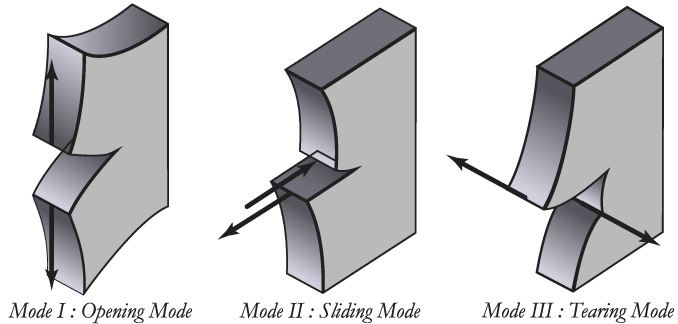
The three basic modes of fracture.
Based on these modes, it is obvious that the knowledge about crack orientation can play a key role in the analysis of structure and materials hence offers very important information on crack behavior and defects in structures and material. In the aim to elucidate the importance of crack orientation, three cases are presented hereinafter.
This case presents a real practical situation of a plate with a crack of length (2a) and an initial orientation angle θ which is considered to be unknown in advance, where a tensile force is applied to the ends of the plate as shown in Fig. 2. The state of the crack is described by the stress intensity factor (SIF) on mixed-modes I, II, which can be expressed as follows [44]:
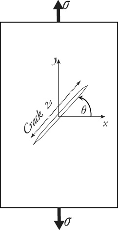
The plate with a central and initial oriented crack under static loading.
In this case, an infinitesimal propagation of the initial crack is supposed with an orientation angle θ compared to the x-axis as shown in Fig. 3(a). The local SIF at the extremity of the propagation following both mixed—modes I and II are defined as follows [45]:
K I , K II : are the SIFs of initial crack.
σ
yy
, τ
xy
: are the normal and tangential stress at the new tip of the crack respectively. C
ij
: are the coefficients, which present the effect of the orientation angle θ of the crack propagation defined as follows:
In this case, let’s consider a homogeneous body of material containing a traction free crack and subjected to two dimensional deformation fields similar to the case presented previously by J.R. Rice in 1968 [30]. In this case, the stresses are depending on the x-axis and y-axis orientations. Indeed, J.R. Rice succeeded in developing an analytical technique that allows obtaining the approximate analysis of the strain concentration using notches and cracks in elastic and elastic-plastic material. This technique was based on the exhibition of a line integral that has the same value along all trajectories encountering the tip of a notch or a crack in the two dimensional strain fields of an elastic material or deformation-type of an elastic-plastic material. Furthermore, this study was extended for the assessment of the crack tip opening displacement and the role of large geometry changes in crack blunting [30]. It was demonstrated that an appropriate choice of the integration path can lead to approximate estimations of the strain concentrations for a variety of notch problems [46,47]. J.R. Rice defined a two-dimensional integral called J-integral which is calculated along a 𝛤 trajectory as shown in Fig. 3(b). It includes the crack tip and the initial and final points, which lie on the two sides of the crack. This integration describes the release of energy related to the growth of the crack and it is expressed as follows [37,40,47]
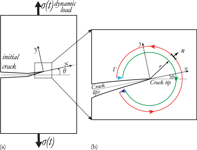
The plate exposed to the crack (a) the localization and orientation of the crack on the plate, (b) a zoom describing the J-integral trajectory of the considered crack.
The resulting stress intensity factor is defined as follows: [47]
A 3D numerical simulation of non-destructive testing (NDT) using eddy current based on finite elements is developed in this paper. This simulation is based on an example of a crack which is occurred in a plate that is supposed to be composed of homogeneous materials, this example presents the model investigated in this paper for the validation of the proposed approach and which is shown in Fig. 4. Wherein, the exciting current circulating in the probe produces an electromagnetic field which leads in turn to two electromagnetic phenomena in the plate such as the propagation of magnetic fields and the induced current.
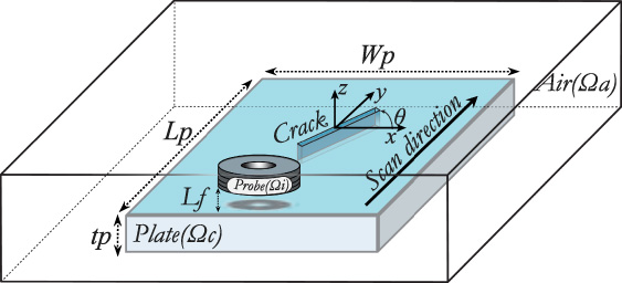
Schema of the cracked plate investigated in this paper under multi-turn excitation coil probe.
The model presented in this example can be modelled using the Maxwell’s equations, where the magnetodynamic equations to be solved are based on the formulation
Based on the application of two methods on Eqs (9) and (10), the first one is the well know mathematical method of Boris Galerkin which allows converting continuous operator problems to a discrete problem by applying linear constraints obtained from finite sets of vector weight functions or shape functions
It can be said that these nodal approximation functions are associated with each node are entirely defined by the x, y, z coordinates of the corresponding mesh nodes.
By substituting Eqs (13) and (14) in Eqs (11) and (12), a global algebraic matrix system is obtained as follows:
A 3D finite element model is used to determine the potential magnetic vector (A) from which the magnetic field density (B) and the eddy current (J) in the studied materials can be calculated. As it has been mentioned the detection of the cracks and its orientation angle can be achieved based on the calculated components of (B) and (J) following the x-axis and y-axis.
In this section, the aforementioned used model is presented for the validation of the proposed approach. It is based on aluminum plate containing an arbitrarily oriented external crack which is scanned by a multi-turn excitation coil probe. For the study of the effect of the magnetic field, the proposed model is placed inside bounding box presented by a cube of dimensions (500 × 500 × 100 mm). The main dimensions of the crack are defined by three parameters such as the length (L c ), the thickness (t c ) and the width (W c ), which are taken equal to 12 mm, 5 mm and 0.3 mm respectively. The model of the probe coil used in this paper is the same model which has been used in several previous studies of many authors as a standard benchmark such as in the references [56–61]. Indeed, this model was proposed for the first time in 1988 within the famous publication of S.K. Burke from the Aeronautical Research Laboratory of the Defence Science and Technology Organisation (DSTO), Autralia [62]. The characteristics of this benchmark model is presented in Table 1. On the other side, the plate which contains the studied crack has the characteristics presented in Table 2.
To obtain the best choice of the probe topology, deep investigations on many existing probe topologies have been checked previously by some authors such as the figure-8-shaped probe which induces a strong near-unidirectional eddy current (NUEC) area between the two coils, unfortunately it has not enough high sensitivity to the crack orientation as reported in [27]. On the other side, it has been found that the tangential and normal rectangular coil topologies induce a weak unidirectional eddy current under the coils which cannot be used for the crack orientation detection [63]. In this paper, the coil topology which was proposed by S.K. Burke has been used for the validation of the proposed approch.
The benchmark coil parameters proposed by S.K. Burke and used in this paper
The parameters of the plate under investigation and in which the crack occurred
The simulation which has been performed in this paper is based on the aforementioned coil topology and the aluminum plate specimen. Where, an alternative current is used to ensure the excitation of the coil and which is defined as follows:
The measurements can be ensured practically by giant magneto-resistive (GMR) tool, however in this simulation they are obtained via the proposed technique which allows the extraction of eddy current and magnetic flux density components.
The meshing adopted in this paper for the used finite elements technique is the tetrahedron meshing as shown in Fig. 5. The meshing is redone automatically in each step of scanning, where the meshed zone under the probe is refined when there is a concentration of magnetic field. Furthermore, the meshing around the crack edge is refined due to the sharp edges and the small dimensions of the crack.
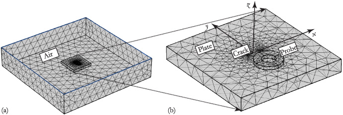
Selected mesh with tetrahedron elements (a) meshing of the all bounding box containing the air, the probe and the plate (b) meshing of the model (probe and plate).
The results of the scanning of the considered model along the chosen path for the five orientation angles have been carried out. Where the obtained two components J x and J y of the eddy current at a given position are depicted in Figs 6 and 7. It can be seen clearly that the orientation of most the eddy current vectors at the proximity of the crack follow the same crack orientation within the five cases as shown in Figs 6(a)–6(e). Indeed, when the crack orientation is parallel to the x-axis, the crack orientation angle is θ =0° as shown in Fig. 6(a), it is obvious in this case that the most of the eddy current vectors are in parallel to the crack along its length. This is due to the neglected value of the y-axis eddy current component J y which leads the component J x to reach its maximum value, this physical behavior can be seen clearly in Figs 7(a) and 7(b). On the other side, when the crack is parallel to the y-axis which corresponds to crack orientation angle θ = 90° as shown in Fig. 6(e). It is obvious that only the eddy current vectors that are very close to the crack follow the same orientation as the crack. Furthermore, as the EC vectors are relatively far from the crack, they lose this feature of following the orientation of the crack, this physical behaviors can be seen clearly in Fig. 6. Indeed, as far as the orientation angle increases the eddy current J x component decreases and the J y component increases, where J x component is nearly neglected and the J y component reaches its maximum value when the crack orientation angle is θ = 90° as shown in Figs 7(i), and 7(j). Whereas, for the other crack orientation angles θ = 30°, θ = 45° and θ = 60° this behavior can be seen clearly as shown in Figs 7(c) and 7(d), Figs 7(e) and 7(f) and Figs 7(g) and 7(h) respectively. It is concluded that the eddy current component J x decreases with the increase of the crack orientation angle, at the same time the eddy current component J y increases with the increase of the crack orientation angle. This main feature can be used in the exact estimation of the orientation of the crack within the structure of the studied model.
In the present simulation, for detecting the nature of crack orientation, a point C j located near the crack is selected for the measurements of the aforementioned components of the eddy current and further for the measurements of the two components of the magnetic flux density as shown in Fig. 6(a).
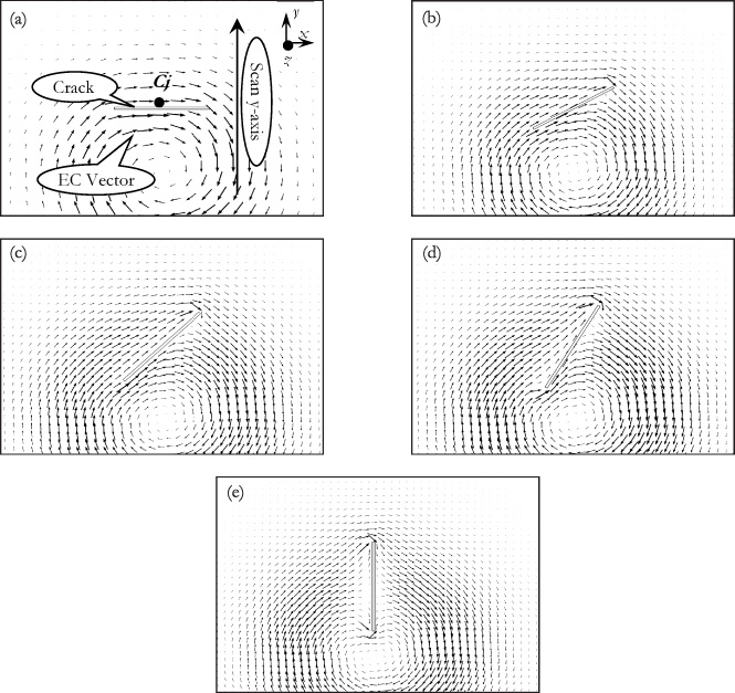
Presentation of eddy current vectors surrounding the crack with different orientation angles (a) θ = 0°, (b) θ = 30°, (c) θ = 45°, (d) θ = 60°, (e) θ = 90°.
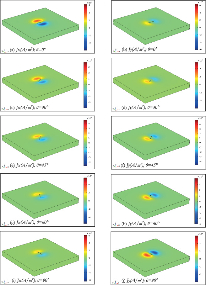
The densities of the eddy current components following x-axis and y-axis for the five crack orientation.
The measurements of two components of the eddy current (J x , J y ) and the two components of the magnetic flux density (B x , B y ) at each step of the scanning path along the y-axis for different crack orientation angles have been carried out. The absolute values of the obtained measurements of (J x , J y ) and (B x , B y ) are depicted in Figs 8 and 9.
It can be observed clearly that the eddy current component J x and the magnetic flux density component B y behave similarly in the same way with a difference of scales from the point of view of the shapeform of the obtained curve as shown in Figs 8(a) and 9(b). The same observation is valid for the obtained curves of the eddy current component J y and the magnetic flux density component B x as shown in Figs 8(b) and 9(a). The cross similarity of these curves can be explained by the fact that each couple of the cross components of the eddy current and magnetic flux density (J x , B y ) and (J y , B x ) are parallel to each other. On the other side, the five obtained curves of the aferementionned componentes of the eddy current (J x , J y ) are shown in Figs 8(a) and 8(b), which are corresponding to the five selected crack orientation angles (0°, 30°, 45°, 60°, 90°), behave in a contrary way, where the order of the curves belonging to J x is inversed compared to the order of the curves belonging to J y . It can be said that the values of J x along the y-axis decrease with the increase of the orientation angle following the obtained curves, which means the curve with the highest values is obtained at θ = 0° and the curves with the lowest values are obtained for θ = 90°, the inverse is observed for the curves of J y . As an example, it can be seen clearly that the J x curve (in green) which is corresponding to the crack orientation angle 0° is the curves with the maximum values along the scanning path as shown in Fig. 8(a). Though the J y curve (in green) which is corresponding to the crack orientation angle 0°, is the curve with the minimum values along the scanning path as shown in Fig. 8(b). The same observations are valid for the curves of the magnetic flux density components (B x , B y ) shown in Figs 8(a) and 8(b). Due to the selected path of scanning following the y-axis the eddy current J x changes direction at the passage by y = 0 mm, however its variation of the both sides of this point gives the same values, this clearly explains the symetrical nature of the curve of the absolute values of J x as shown in Fig. 8(a). Whereas, J y does not change the direction along the scanning path as shown in Fig. 8(b).
On the other side, important characteristics can be observed between the J x and B x in one hand and J y and B y in the other hand, which present the same observation registered between the curves of (J x and J y ) due to the similarity of curves between (J x and B y ) and (J y and B x ) as explained above. As an exemple, it can clearly be seen that for the crack orientation angle 0°, J x (green curve) takes the maximum values as shown in Fig. 8(a) while B x (green curve) takes the minimun values as shown in Fig. 9(a), this can be explained further by the fact that the resulting magnetic field from the coil is perpendicular to the lines of the induced eddy current in the plan of the studied model. This can also be observed in the same way between J y (green curve) which takes the minimum values and it is nearly equal to zero as shown in Fig. 8(b), and B y (green curve) that takes the maximum values as shown in Fig. 9(b).
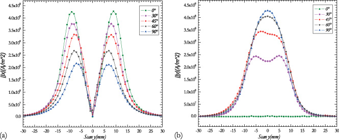
Eddy current density values at different crack orientation (a) J x component, (b) J y component.
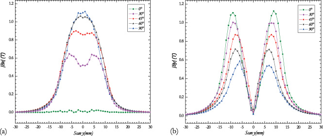
Magnetic flux density values at different crack orientation (a) B x component, (b) B y component.
It is worthy to clarify that at positions y = −30 mm, y = 0 mm and y = +30 mm J x is null for all the orientation angles and J y is null for all the orientation angles at only y = −30 mm and y = +30 mm. This is because the chosen measurment point C j is located near the crack.
Based on the obtained results, the crack orientation angle function of the peak values of (J x and J y ) and (B x and B y ) corresponding to the five considered crack orienation angles are plotted as shown in Figs 10 and 11 respectively. In this paper a simple interpolation of the four obtained curves is proposed to obtain their corresponding fitting functions. It is found that J x and B y curves can be fitted by using a cubic function due to their similarity as shown in Figs 10(a) and 11(b) respectively. While J y and B x curves can be fitted by an exponential function due to their similarity as shown in Figs 10(b) and 11(a) respectively.
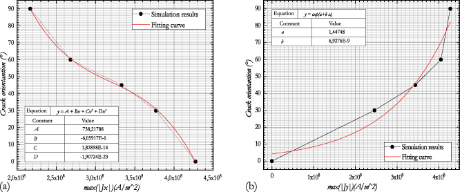
Comparison between the maximum values of the eddy current density obtained from the model and the proposed empirical model following different crack orientation angles (a) J x component, (b) J y component.
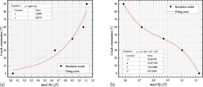
Comparison between the maximum values of the magnetic flux density obtained from the model and the proposed empirical model following different crack orientation angles (a) B x component, (b) B y component.
The obtained fitting functions are proposed to be as special empiric functions for the studied model of the cracked plate, which can be used to calculate the crack orientation angle directly from measured eddy current. Hereinafter, this angle is used to calculate the mechanical parameters of the analyzed structure such as the stress intensity factor SIF presented in Section 2 which can be represented as follows:
Calculate the SIF and the integral-J of this arbitrarily oriented crack using the eddy current.
In this paper, the main idea resides on the determination of the values of the two eddy currents components following the x-axis and y-axis, and the two components of the magnetic flux density following the x-axis and y-axis. It is proved through the study of the model presented in this paper that the crack orientation angle clearly affects the values of these four components depending on the degree of orientation and the position of the probe. The obtained results based on the 3D finite element study of the proposed model signifies the important influences of the crack orientation angle on the mentioned components of the eddy current and the magnetic flux density. Therefore, an empirical model is constructed using simple interpolation technique that can be applied to estimate the angle orientation of the crack in the structure. Finally, the estimated crack angle orientation is used for the calculation of the stress intensity factor SIF components and the J-integral components, which gives precise details on the severity and the quality of the degradation of the structure caused by the crack. This allows to avoid major damage and risks that may happen to the studied structure and to identify the estimated remaining life of such structure. A complete design and sizing of the real tool of the probe is considered as a perspective of the obtained results based on the proposed technique in this paper.
In light of the previous results, it has been noticed that this technique is quite effective and provides very accurate results as well as it is applicable in laboratory experiments due to its ease of conception and its low budget cost. The angle of crack orientation has a large influence, and precise sensibility on the components of eddy current and magnetic flux density. The results provided enable the prediction of crack propagation using the fracture parameters as SIF, J-integral, CTOD under dynamic or fatigue loading. Through the use of NDT-EC all parameters of fracture mechanics mentioned in this paper can be utilized directly, especially for embedded or micro cracks, due to its precision, ease of access, and performance. Using the advanced sensing technology, it is possible to support the concepts of classic fracture mechanics which remain limited and theoretical in use unlike NDT and sensing technique which is more practical.