
Abstract
In recent years, the necessity for inspection of the deteriorated oil-refining plant is increased. In the steel tube to be used in a heating furnace has carburizing phenomenon is the cause of the accident. As these carburizing depths increase, so does the steel tube. Therefore, inspection of these depths is important. Therefore, studies are being conducted to determine the life of steel tube by applying electromagnetic non-destructive inspection electromagnetic. However, it is difficult to put it to practical use in the field because measurement error occurs due to the effect of lift-off. In this paper, we proposed an inspection method that can measure carburizing depth and lift-off at the same time. This method uses two types of search coil. One is the magnetic flux testing and the other is the eddy current testing.
Keywords
Introduction
In the heating furnace of an oil refining plant, carburizing of steel tube is the cause of the accident. A cross-section macro test is used to inspect the carburizing depth. However, this method is a destructive inspection. There is an increasing need for non-destructive inspection methods that save time and money. The authors have proposed a non-destructive inspection method for estimating the carburizing depth using two types of alternating magnetic fields. This method made it possible to estimate the carburizing depth generated on the surface and opposite side of the steel tube [1]. However, the effect of lift-off caused a measurement error. In this paper, a new non-destructive inspection method for measuring carburization depth and lift-off at the same time was proposed. In this method, an inspection method using the detection characteristics of the magnetic leakage flux testing and eddy current testing. In addition, the phenomenon was elucidated by 3D nonlinear FEM.
Measurement results by the proposed electromagnetic sensor
Proposed electromagnetic sensor and experimental conditions
Figure 1 shows the proposed model for inspecting the carburization depth and lift-off in steel tube. This model is composed of the yokes (lamination of silicon steel plates) for ac (alternating) magnetic field and a search coil. In addition, there are two search coils, search coil 1 and search coil 2. Exciting coil is set to 100 Hz with 40 Ampere-turns. Search coil 1 is inspected by the magnetic leakage flux testing. As for the search coil in this sensor, the x-direction flux density (B x ) of the magnetic field on the surface of the steel tube is detected. Search coil 2 is inspected by the eddy current testing. As for the search coil in this sensor, the z-direction flux density (B z ) of the magnetic field is detected. The steel tube used STFA26. The diameter is 114 mm and the thickness is 6 mm. The surface carburization depths used in this research are 0 mm, 1.15 mm, 2.15 mm and 2.99 mm. The distance (lift-off : Lo) between the sensor and the surface of steel tube is equal to 0.1–0.5 mm. Figure 2 shows initial magnetization curves of the steel tube (STFA26) with and without carburization layer. The carbon concentration of the carburization layer is equal to 3.8 %. The figure denotes that the permeability in the steel tube is decreased by the carburization. Figure 3 shows the example of measurement result of carbon concentration inside steel tube using electron probe-micro analysis (EPMA). The domain that the carbon concentration is more than 0.27 % is defined as the carburization layer. The figure denotes that the carbon concentration in the carburization layer is nonlinearly distributed. The maximum carbon concentration is 3.8 % and the minimum is 0.27 %. The conductivities of the steel tube with and without carburization are 2.45 ×10⁶ S/m and 1.91 ×10⁶ S/m, respectively. The conductivity in the steel tube is increased with the carburization [2–5].
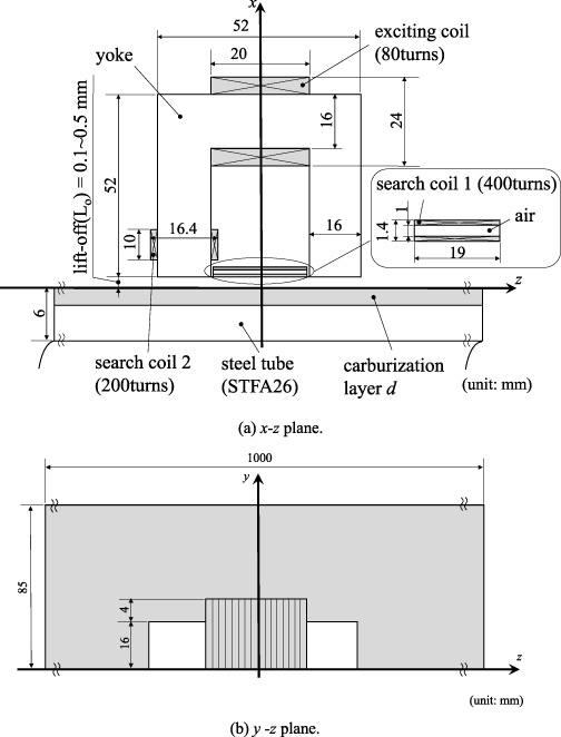
Inspection model for an carburization depth and lift-off in steel tube (STFA26).
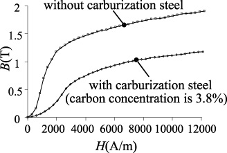
Initial magnetization curves of the steel tube (STFA26) with and without carburization layer.
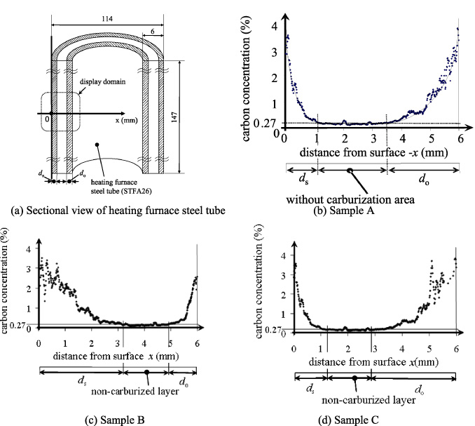
The example of measurement result of carbon concentration inside steel tube using electron probe-micro analysis (EPMA).
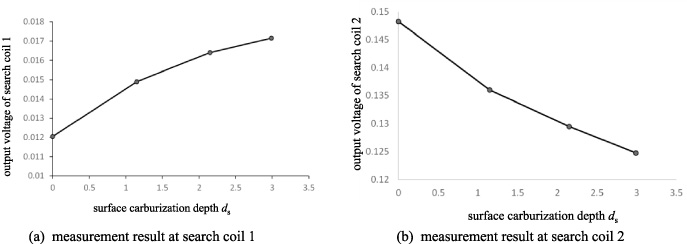
The result of surface carburizing depth d s measurement by the proposed electromagnetic sensor. Lift-off is constant at 0.1 mm.
Figure 4 shows the result of surface carburizing depth d s measurement by the proposed electromagnetic sensor. Lift-off is constant at 0.1 mm. The horizontal axis and the vertical axis in this figure are the surface carburization depth d s and the output voltage of search coil, respectively. Figure 4(a) shows the experimental results of leakage flux testing (search coil 1). Fig. 4(b) shows the experimental results of eddy current testing (search coil 2). This figure denotes that the output voltage of search coil 1 increases as the carburizing depth increases. Also, the output voltage of search coil 2 decreases as the carburizing depth increases. Figure 5 shows the measurement result of the lift-off size by the proposed electromagnetic sensor. The carburizing depth is constant at 0 mm. The horizontal axis and the vertical axis in this figure are the lift-off size and the output voltage of search coil, respectively. Figure 5(a) shows the experimental results of leakage flux testing (search coil 1). Figure 5(b) shows the experimental results of eddy current flaw detection testing (search coil 2). This figure denotes that the output voltage of search coil 1 increases as the lift-off size increases. Also, the output voltage of search coil 2 decreases as the lift-off size increases. It can be seen that the tendency of output voltage obtained is opposite for leakage flux testing and eddy current testing. Also, the tendency of these figure was also found different carburizing depth measurement and a lift-off size measurement.
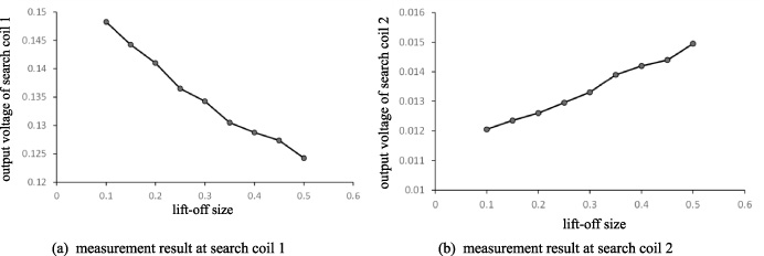
The measurement result of the lift-off size by the proposed electromagnetic sensor. The carburizing depth is constant at 0 mm.
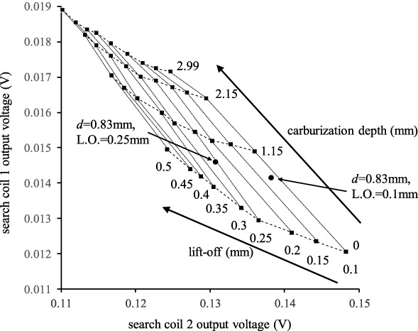
Calibration curve for measuring carburized depth and the lift-off size at the same time.
Figure 6 shows the results obtained in Fig. 4 and Fig. 5, calibration curve for measuring carburized depth and the lift-off size at the same time was obtained. The vertical axis shows the voltage signal obtained in search coil 1, and the horizontal axis shows the voltage signal obtained in search coil 2. As a result of measuring condition (carburization depth d s = 0.83 mm, Lift-off = 0.1 mm) and condition (carburization depth d s = 0.83 mm, Lift-off = 0.25 mm), it can be seen that the carburizing depth can be inspected at the same time for lift-off as shown in Fig. 6.
Phenomenon comparison of 3D non-destructive inspection and experimental result
Analysis method and condition setting
3-D FEM using the 1st order hexahedral edge element is applied. The flux and eddy current are analyzed by the step-by-step method taking account of the non-linearity of the steel tube. Moreover, an initial magnetization curve of the magnetic yoke is also taken into consideration, but the eddy current is neglected. In order to get the steady state result, the calculation is carried out during 3 periods (= 40 steps).
The basic equation of eddy current analysis using the
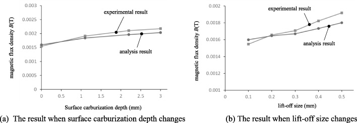
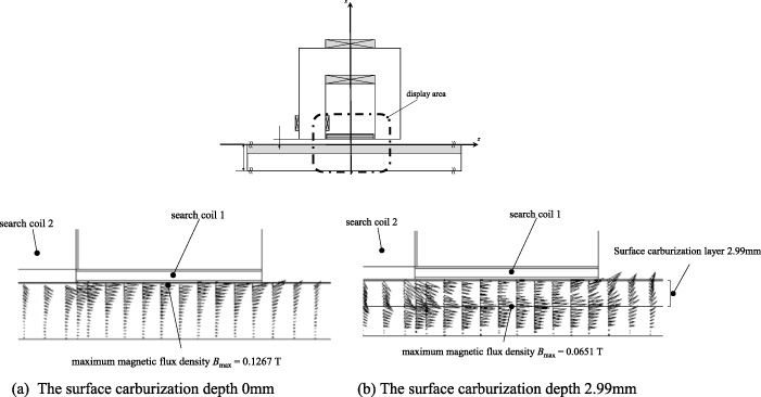
Figure 7 shows the comparison result of the magnetic flux density obtained by the search coil 1 of the analysis result and the experiment result. Figure 7(a) shows the result when surface carburization depth changes, and Fig. 7(b) shows the result when lift-off size changes. These results, similar tendency as numbers and experiment was found to be obtained from the analysis. Also, it can be seen that the difference between the experimental value and the analytical value increases as the carburization depth and lift-off increase. It is thought that an error occurred in the leakage magnetic flux value because the conditions in the air differed the experiment and the analysis. Figure 8 shows the magnetic flux distribution in the thick part of the steel tube. Figure 8(a) shows the magnetic flux distribution when the carburizing is 0 mm. This figure illustrate that the flux density is distributed on the surface of the steel tube by a skin effect. Also, Figure 8(b) is a magnetic flux distribution when the carburization of 2.99 mm has occurred on the surface. This figure illustrate that the maximum flux density in steel tube is decreased when the surface carburization depth is increased since the permeability in the carburization layer is lower than that of the non-carburization layer. Also, the maximum flux density in steel tube is on the border of carburization layer in Fig. 8(b). These results increase the leakage flux of the carburized depth is increased, it can be seen that the magnetic reluctance is increased. Therefore, search coil 1 output voltage increases and search coil 2 output voltage decreases as the carburization depth increases. In addition, the magnetic flux that penetrates the steel tube decreases due to the increase in lift-off. Therefore, search coil 1 output voltage decreases and search coil 2 output voltage increases as the lift-off size increases.
Comparison of analysis result and experimental result of search coil 1.
The magnetic flux distribution in the thick part of the steel tube.
The results obtained by this research are summarized as follows:
It was found that the proposed electromagnetic sensor can measure the surface carburizing depth and lift-off at the same time. In the leakage flux testing, the output voltage increases as the carburization depth increases, and the output voltage decreases as the lift-off size increases. The eddy current testing was the opposite of the result of the leakage flux testing. Using this characteristic, it was created calibration curve. This method eliminates the error of the output voltage due to lift-off and makes it possible to improve the detection accuracy. From the nonlinear 3D FEM analysis results, it was found that the increase in surface carburization depth increases the reluctance of the steel tube surface. In addition, the magnitude of the magnetic flux leaking to the surface of the steel tube increases. As a result, in the leakage flux testing, the output voltage increases as the carburization depth increases, and the output voltage decreases as the lift-off size increases. Also, in the eddy current testing, the output voltage decreases as the carburization depth increases, and the output voltage increases as the lift-off increases.