
Abstract
A temperature sensor based on the combination of a temperature variable oscillator and a linear controlled oscillator is proposed, which can realize temperature detection through the characteristic of frequency changing with temperature. The changing frequency is generated by the two oscillators, and by adjusting the frequency linear change, the linearity of the sensor is also increased. Through the frequency digitizer, the digital signal can be output. Compensation through a process compensator improves the accuracy of the sensor after a single point correction. After conducting tests on 15 experimental samples, the accuracy was achieved within
Introduction
With the continuous updating and iteration of advanced electronic equipment, accurate temperature detection and control are becoming more and more important for microprocessor thermal management, dynamic random access memory refresh control and other technologies, and the realization of these technologies requires temperature sensors [1]. It is necessary for the sensor to have as small a volume as possible, as low as possible power consumption, as high as possible accuracy, and as large a measurement range as possible, which are all key requirements for temperature sensors [2].
Precise band-gap temperature sensors based on analog-to-digital converters [3, 4] and temperature sensors based on thermal diffusivity sensing [5] are not suitable because of the high energy consumption and large area of this type of sensor [6]. Therefore, researchers have successively proposed temperature sensors based on delay lines that vary with temperature, temperature sensors with timing comparators, and temperature sensors based on delay-locked loops.
However, in order to achieve satisfactory temperature measurement resolution, traditional temperature sensors require hundreds of inverters, and due to loop capacitors, the area of the sensor is quite large, and the power consumption is also large, so that there is sufficient delay [7, 8]. In addition, when the power supply voltage changes, it does not operate correctly. Generally, the temperature detection accuracy based on the inverter delay module is only 3
The internal structure of temperature sensor in this paper.
The relationship of oscillator frequency with temperature.
Therefore, a double oscillator structure is designed in this paper. The two oscillators are composed of temperature variable oscillator and linear control oscillator, which can improve the linearity of the sensor. The innovation is that one of the ring oscillators is inversely temperature-dependent, so that the frequency difference changes linearly with temperature. In addition, compared with the previous temperature detection [7], the error of the temperature sensor is reduced by using the process compensation scheme and power regulation, which is caused by process deviation and power instability. It is done using a 65 nm CMOS process with an area of only 0.01 square millimeters. The maximum error of temperature sensor is
The internal structure of the temperature sensor is shown in Fig. 1. This temperature sensor contains two oscillators. One of them is an oscillator that changes with temperature called a “temperature oscillator”, which can generate a frequency difference that changes with temperature. The other is a linearly controlled oscillator, which can improve the linearity of the sensor. However, because the bias circuit is different, each oscillator will have its own distinct characteristics. In a temperature-varying oscillator, its delay time and the oscillator’s series determine its frequency. Similarly, the mobility of a field-effect transistor (MOSFET) and the threshold voltage both decrease with increasing temperature. Since the mobility is significantly reduced, the frequency of the oscillator is negative in relation to temperature, that is, the temperature increases while the frequency decreases, as shown in Fig. 2(a). In the process corner FF TT SS, t stands for typical, s stands for slow (low current), and f stands for fast (high current). Generally, the first letter stands for nmos and the second letter stands for pmos (for example, TT means that nmos and pmos are typical). Generally, the temperature of a ring oscillator is nonlinear to its frequency. This leads to an increase in the error of the temperature sensor. It can be seen from the frequency temperature characteristic curve that if only one oscillator is used, the linear relationship between frequency and temperature cannot be obtained. Therefore, a linearly controlled oscillator is required to generate linearized frequency differences. The linear controlled oscillator can generate an output signal with positive frequency and temperature characteristics, that is, the frequency increases as the temperature increases, as shown in Fig. 2(b). The frequency difference obtained by adjusting the frequency characteristics is more linear. Because the temperature variable oscillator and the linear control oscillator have the same structural basis, the process variation can cancel each other out. The temperature sensor produced by this process not only has improved resolution, but also has higher accuracy, as measured in Fig. 2(c).
The power regulator is used for power regulation, the compensator is used for variation compensation, the controller generates the control signal for all operations, and the output digital signal is converted into the frequency difference by the frequency digitizer. Therefore, the output obtained is not sensitive to process variation as well as power supply variation.
Proposed oscillator and bias circuit design
The content structure of the temperature variable oscillator and the linear control oscillator is shown in Fig. 3. The ring oscillator consists of a current-driven delay module that can be used to promote common-mode noise suppression. Polyphase clocks are used to generate high-resolution digital outputs.
Binary weighted current driven delay unit.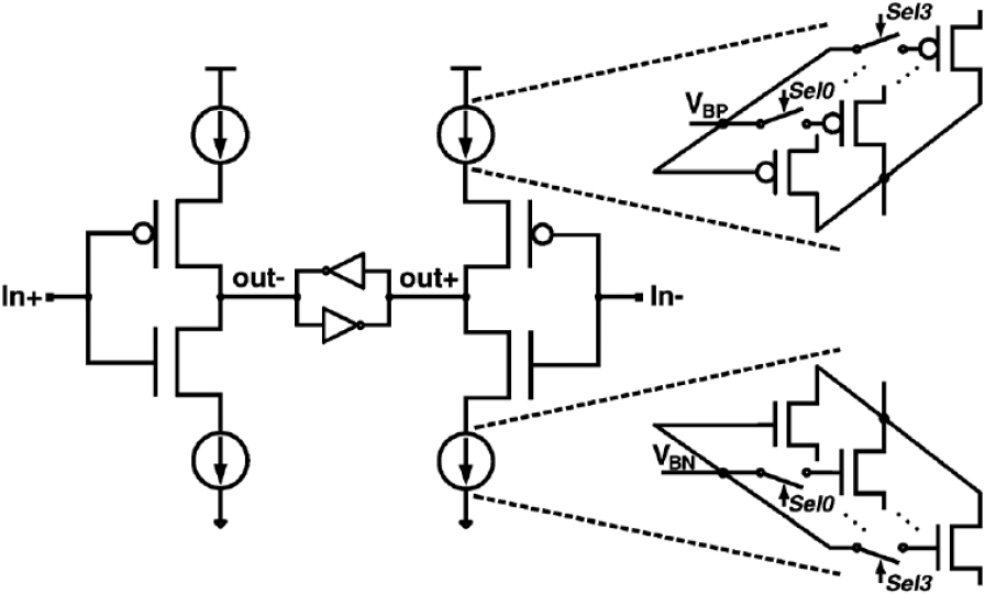
Due to the voltage peak reserve problem, it is difficult to implement the bias circuit of a conventional temperature sensor when the supply voltage is reduced to 1.2 V, as shown in Fig. 4(a). Because it is composed of three MOSFETs stacked, and the threshold voltage of each is less than half of the power supply, its sensitivity is extremely low. To solve this problem, this article uses another structure, as shown in Fig. 4(b). In the picture, the M4 and M7 play the same role as the M1, which ensures that the device operates in a saturated region. The use of this structure can save voltage. If the voltage of the bias circuit exceeds the threshold voltage of the transistor, both M4 and M7 are connected. M7 is connected to the supply voltage level and the source of M8. Diode connection PMOS M8 will turn on. The VBN can charge it via the M8. When the VBN voltage exceeds the threshold voltage, M6 and M9 will also turn on. Finally, the bias voltages VBP and VBN can be obtained.
The bias circuit of the oscillator.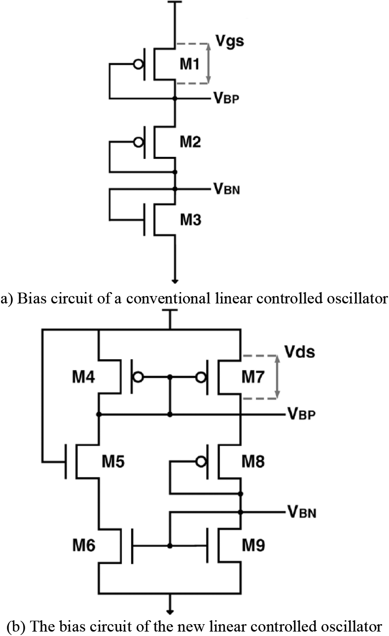
With the increase of temperature, the
According to
The reason is that the M8 operates in a saturated region. The coefficient
Where,
If we extend the .
Where
The delay of the delay module and the series of the oscillator determine the frequency F of the oscillator. The current of the delay module determines
Among them, Cload is the output point capacitance of each delay module,
Among them,
Delay unit time and saturation current are easily affected by fabrication variation. In this paper, the signal Sel
Figure 5 is a block diagram of the process compensator, and Fig. 6 is its timing diagram. Figure 2 shows the relationship between the process conditions and the oscillator frequency. Then the process variation can be reflected by the frequency change of the oscillator, which is the role of the process compensator. The frequency range of the oscillator at the specified temperature in Fig. 5 can be detected by the “switch counter”, whose output is: q0
Block diagram of process compensator.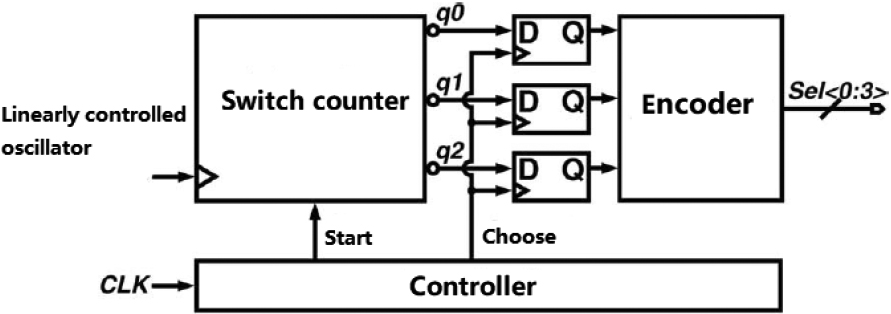
Sequence diagram of process compensator.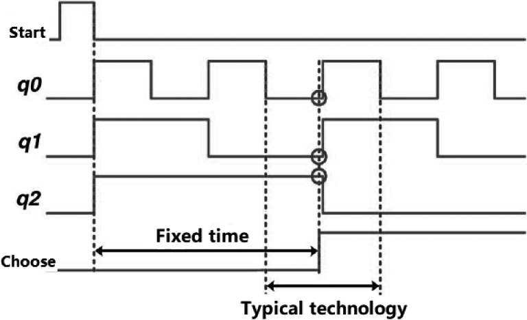
Schematic diagram of frequency digital converter.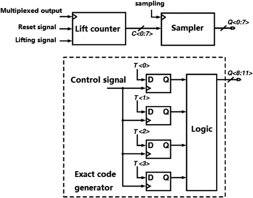
The block diagram of the frequency digitizer is shown in Fig. 7, which includes an 8 bit lift counter, a sampler, and an exact code generator. Figure 8 is a timing diagram of the frequency digitizer. If it is a test mode, the frequency difference is calculated by the control signal and its calculated value is saved. When the count signal is “1”, the output value of the temperature variable oscillator becomes the input clock selected by the multiplexer to the digitizer. The counter then increases the rising edge of the input clock. Similarly, when the lift counter signal is “0”, the multiplexer outputs the input clock to the frequency digitizer using a linear control oscillator. At the same time, the rising edge of the input clock is reduced by the input of the computer. Every time a cycle is completed. The sampled signal will become a “1” and the sampler will store the value in the counter. In this way, the frequency digitizer can calculate and store the frequency difference between the temperature-varying oscillator and the linear-controlled oscillator until the sampler is “1” again. If you need to measure again, input a new signal will reset the counter, which is a complete digital temperature measurement. The conversion time is the same as the computer signal cycle. In order to prevent overflows, the frequency
Frequency digitizer timing diagram.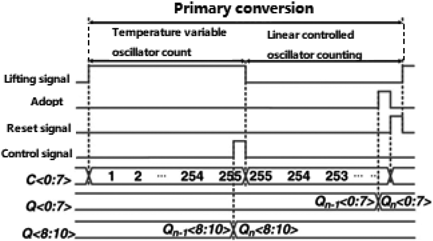
Quantization error of precision code generator.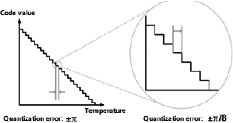
The frequency of the lift signal is as follows, which can make the counter optimal:
Finally:
In the precision code generator, the control signal can be used to sample the four polyphase clocks (temperature-varying oscillators
The four polyphase clocks in this article increase the resolution by a factor of eight, as shown in Fig. 7. Compared to using an 11 bit counter, the precision code generator does not increase the resolution, but it can increase the measurement bandwidth by 3 times.
The relationship between frequency and temperature in an analog temperature-varying oscillator.
Simulation of the relationship between frequency and temperature in a linear controlled oscillator.
Simulation results of linearized frequency difference between two oscillators.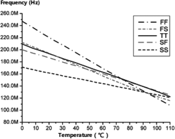
Relationship between temperature and frequency.
Under different process Angle conditions, the relationship between temperature and frequency of temperature variable oscillator and linear controlled oscillator is shown in Figs 10 and 11. If only the temperature variable oscillator is used for temperature sensing, the output code needs to be uniform under all process conditions using a two-point correction method. In addition, even if the two-point correction method is used, there may be large errors in different process angles due to nonlinear characteristics. This problem can be solved by using the frequency difference between the two oscillators, as shown in Fig. 12. Because the linear controlled oscillator is adjusted to compensate for the nonlinear characteristics of the temperature variable oscillator, the frequency difference is linearized at all process angles. However, the output code of this method still needs to be corrected at two points. In addition, the current of the delay unit also needs to be controlled by the process compensator and the selection signal. It’s the only way to compensate for process variation. Figure 13(a) is obtained after single-point process compensation in the same temperature range. Figure 13(b) shows the output error of the temperature sensor.
Performance comparison of temperature sensors in this paper
Performance comparison of temperature sensors in this paper
Equipment for temperature sensor experiments.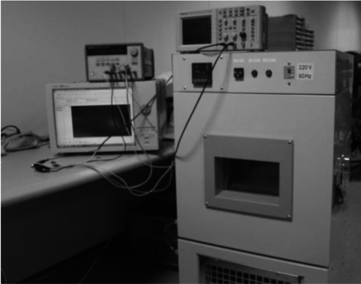
Measurement error of 15 sensor chips.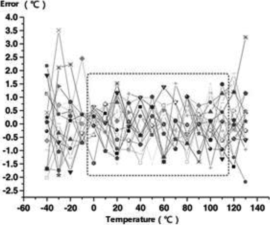
The temperature sensor in this paper is designed using 65 nm CMOS technology. Figure 14 shows the experimental setup for testing the chip. The thermostatic model number is QRTH-781U, which is used for temperature control, the oscilloscope model is GDS-1062A, and the function signal generator is HP33120A. In the process compensation operation, first set the temperature to the middle of the temperature measurement range (such as 40
Conclusion
This paper presents a CMOS temperature sensor with two oscillators. The sensor uses an adaptive ring oscillator and an additional process compensator to improve linearity and process immunity. After using the one-point correction method, the maximum error of the temperature sensor is
Footnotes
Acknowledgments
This project was funded by Chongqing Education Science planning project “Three Education Reform and Practice Research Based on the Construction of Two Platforms and one Workshop integrating Production and Education with gold Class” project No. 2021-GX-046.